Table of Contents
Advertisement
Advertisement
Table of Contents

Related Manuals for Asus P5VD2-VM SE


Summary of Contents for Asus P5VD2-VM SE
- Page 1 P5VD2-VM SE...
- Page 2 Product warranty or service will not be extended if: (1) the product is repaired, modified or altered, unless such repair, modification of alteration is authorized in writing by ASUS; or (2) the serial number of the product is defaced or missing.
-
Page 3: Table Of Contents
Contents Notices ......................vi Safety information ..................vii About this guide ..................viii P5VD2-VM SE specifications summary ............. x Chapter 1: Product introduction Welcome! ..................1-2 Package contents ................. 1-2 Special features ................1-2 1.3.1 Product highlights ............1-2 1.3.2 Innovative ASUS features .......... - Page 4 Creating a bootable floppy disk ........2-5 2.1.3 ASUS EZ Flash utility ............2-6 2.1.4 AFUDOS utility- ............... 2-7 2.1.5 ASUS CrashFree BIOS 2 utility ........2-10 BIOS setup program ..............2-12 2.2.1 BIOS menu screen ............2-13 2.2.2 Menu bar ............... 2-13 2.2.3...
- Page 5 3.2.3 Utilities menu ..............3-4 3.2.4 Make Disk menu ............. 3-6 3.2.5 Manuals menu ..............3-6 3.2.6 ASUS Contact information ..........3-7 3.2.7 Other information ............3-8 RAID configurations ..............3-10 3.3.1 RAID definitions ............3-10 3.3.2 Installing Serial ATA (SATA) hard disks ......3-11 3.3.3...
-
Page 6: Notices
Notices Federal Communications Commission Statement This device complies with Part 15 of the FCC Rules. Operation is subject to the following two conditions: • This device may not cause harmful interference, and • This device must accept any interference received including interference that may cause undesired operation. -
Page 7: Safety Information
Safety information Electrical safety • To prevent electrical shock hazard, disconnect the power cable from the electrical outlet before relocating the system. • When adding or removing devices to or from the system, ensure that the power cables for the devices are unplugged before the signal cables are connected. -
Page 8: About This Guide
Refer to the following sources for additional information and for product and software updates. ASUS websites The ASUS website provides updated information on ASUS hardware and software products. Refer to the ASUS contact information. Optional documentation Your product package may include optional documentation, such as warranty flyers, that may have been added by your dealer. -
Page 9: Conventions Used In This Guide
Conventions used in this guide To make sure that you perform certain tasks properly, take note of the following symbols used throughout this manual. DANGER/WARNING: Information to prevent injury to yourself when trying to complete a task. CAUTION: Information to prevent damage to the components when trying to complete a task. -
Page 10: P5Vd2-Vm Se Specifications Summary
P5VD2-VM SE specifications summary LGA775 socket for Intel Core™2 Duo/Pentium ® ® Pentium 4/Celeron D processors ® ® Supports Intel EIST/EM64T/Hyper-Threading Technology Chipset Northbridge: VIA P4M900 Southbridge: VIA VT8237S Front side bus 1066/800/533 MHz Memory 2 x 240-pin DIMM sockets support up to 4 GB unbufferred... - Page 11 P5VD2-VM SE specifications summary Rear panel 1 x Parallel port 1 x LAN (RJ-45) port 4 x USB 2.0/1.1 ports 1 x VGA port 1 x COM port 1 x PS/2 keyboard port 1 x PS/2 mouse port 6-Channel Audio I/O ports BIOS features 4 Mb Flash ROM, AMI BIOS, PnP, DMI2.0, WfM2.0,...
-
Page 13: Chapter 1: Product Introduction
This chapter describes the motherboard features and the new technologies it supports. Product introduction ASUS P5VD2-VM SE... -
Page 14: Welcome
® The motherboard delivers a host of new features and latest technologies, making it another standout in the long line of ASUS quality motherboards! Before you start installing the motherboard, and hardware devices on it, check the items in your package with the list below. - Page 15 The motherboard supports the S/PDIF Out function through the S/PDIF interface at midboard. The S/PDIF technology turns your computer into a high-end entertainment system with digital connectivity to powerful audio and speaker systems. See page 1-30 for details. ASUS P5VD2-VM SE...
-
Page 16: Innovative Asus Features
ROM chip. See page 2-10 for details. ASUS EZ Flash With the ASUS EZ Flash, you can easily update the system BIOS even before loading the operating system. No need to use a DOS-based utility or boot from a floppy disk. -
Page 17: Before You Proceed
The illustration below shows the location of the onboard LED. ® SB_PWR P5VD2-VM SE P5VD2-VM SE Onboard LED Standby Powered Power ASUS P5VD2-VM SE... -
Page 18: Motherboard Overview
Place six (6) screws into the holes indicated by circles to secure the motherboard to the chassis. Do not overtighten the screws! Doing so can damage the motherboard. Place this side towards the rear of the chassis ® P5VD2-VM SE Chapter 1: Product introduction... -
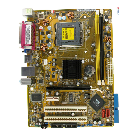
Page 19: P5Vd2-Vm Se Motherboard Layout
1.5.3 P5VD2-VM SE Motherboard layout 17.8cm (7.0in) PS/2KBMS T: Mouse B: Keyboard ATX12V COM1 LGA775 CHA_FAN USB34 CPU_FAN CR2032 3V P4M900 LAN1_USB12 Lithium Cell CMOS Power Top:Line In Center:Line Out Chip Below:Mic In ® PCIEX16 Super PCIEX1_1 VT8237S PCI1 P5VD2-VM SE... -
Page 20: Central Processing Unit (Cpu)
Contact your retailer immediately if the PnP cap is missing, or if you see any damage to the PnP cap/socket pins/motherboard components. ASUS will shoulder the cost of repair only if the damage is shipment/transit-related. - Page 21 Load plate Position the CPU over the socket, making sure that the gold triangle is on the bottom-left corner of the socket. The socket alignment key should fit into Alignment key the CPU notch. Gold triangle mark ASUS P5VD2-VM SE...
- Page 22 Close the load plate (A), then push the load lever (B) until it snaps into the retention tab. The CPU fits in only one correct orientation. DO NOT force the CPU into the socket to prevent bending the connectors on the socket and damaging the CPU! Notes on Intel Hyper-Threading Technology ®...
-
Page 23: Installling The Cpu Heatsink And Fan
Place the heatsink on top of the installed CPU, making sure that the four fasteners match the holes on the motherboard. Fastener Motherboard hole Make sure each fastener is oriented as shown, with the narrow groove directed outward. ASUS P5VD2-VM SE 1-11... - Page 24 CPU FAN IN ® CPU FAN PWM P5VD2-VM SE P5VD2-VM SE CPU fan connector Do not forget to connect the CPU fan connector! Hardware monitoring errors can occur if you fail to plug this connector. 1-12 Chapter 1: Product introduction...
-
Page 25: Uninstalling The Cpu Heatsink And Fan
Disconnect the CPU fan cable from the connector on the motherboard labeled CPU_FAN. Rotate each fastener counterclockwise. Pull up two fasteners at a time in a diagonal sequence to disengage the heatsink and fan assembly from the motherboard. ASUS P5VD2-VM SE 1-13... - Page 26 Remove the heatsink and fan assembly from the motherboard. Rotate each fastener clockwise to reset the orientation. Narrow end of the groove The narrow end of the groove should point outward after resetting. (The photo shows the groove shaded for emphasis.) 1-14 Chapter 1: Product introduction...
-
Page 27: System Memory
Refer to the DDR2 Qualified Vendors List on the next page for details. • Due to chipset resource allocation, the system may detect less than 4 GB system memory when you installed two 2 GB DDR2 memory modules. ASUS P5VD2-VM SE 1-15... - Page 28 Qualified Vendors Lists (QVL) DDR2-667 MHz capability DIMM support Size Vendor SS/DS Chip No. Part No. 256MB Kingston KVR667D2N5/256 E2508AB-6E-E 512MB Kingston KVR667D2N5/512 D6408TE8WL-27 1024MB Kingston KVR667D2N5/1G D6408TE8WL-3 1024MB Kingston KVR667D2N5/1G D6408TEBGGL3U 512MB Samsung KR M378T6553CZ0-CE6 K4T51083QC 512MB Samsung KR M378T6453FZ0-CE6 K4T56083QF-ZCE6 512MB Samsung...
- Page 29 Heat-Sink Package 512MB TEAM TVDD512M667C5 T2D648MT-6 1024MB TEAM TVDD1.02M667C4 T2D648PT-6 512MB Century CENTURY 512MB NT5TU64M8AE-3C 512MB Century CENTURY 512MB HY5PS12821AFP-Y5 1024MB Century CENTURY 1G NT5TU64M8AE-3C 512MB KINGBOX 512MB 667MHz EPD264082200-4 1024MB KINGBOX DDRII 1G 667MHz EPD264082200-4 ASUS P5VD2-VM SE 1-17...
- Page 30 Qualified Vendors Lists (QVL) DDR2-533 MHz capability DIMM support Size Vendor SS/DS Chip No. Part No. 256MB Kingston KVR533D2N4/256 E5116AB-5C-E 256MB Kingston KVR533D2N4/256 E5116AF-5C-E 512MB Kingston KVR533D2N4/512 HY5PS56821F-C4 512MB Kingston KVR533D2N4/512 HYB18T512800AF3733336550 1024MB Kingston KVR533D2N4/1G D6408TE7BL-37 256MB Samsung M378T3253FG0-CD5 K4T56083QF-GCD5 512MB Samsung M378T6553BG0-CD5...
- Page 31 VERITECH GTP512HLTM46DG VTD264M8PC6G01A164129621 1024MB VERITECH GTP01GHLTM56DG VTD264M8PC6G01A164129621 Side(s): SS - Single-sided DS - Double-sided DIMM support: Supports one module inserted in any slot as Single-channel memory configuration Supports one pair of modules inserted into both slots ASUS P5VD2-VM SE 1-19...
-
Page 32: Installing A Dimm
1.7.3 Installing a DIMM Make sure to unplug the power supply before adding or removing DIMMs or other system components. Failure to do so may cause severe damage to both the motherboard and the components. Unlock a DIMM socket by pressing DDR2 DIMM notch the retaining clips outward. -
Page 33: Expansion Slots
Turn on the system and change the necessary BIOS settings, if any. See Chapter 2 for information on BIOS setup. Assign an IRQ to the card. Refer to the tables on the next page. Install the software drivers for the expansion card. ASUS P5VD2-VM SE 1-21... -
Page 34: Interrupt Assignments
1.8.3 Interrupt assignments Priority Standard function System Timer Keyboard Controller – Redirect to IRQ#9 Communications Port (COM)* IRQ holder for PCI steering* Floppy Disk Controller * Printer Port (LPT1)* System CMOS/Real Time Clock IRQ holder for PCI steering* IRQ Holder for PCI Steering* PCI-E x1 PS/2 Compatible Mouse Port* Numeric Data Processor... -
Page 35: Pci Slots
PCI Express x1 slot. 1.8.6 PCI Express x16 slot This motherboard supports PCI Express x16 graphic cards that comply with PCI Express specifications. The figure shows a graphics card installed on the PCI Express x16 slot. ASUS P5VD2-VM SE 1-23... -
Page 36: Clear Rtc Ram
CLRTC P5VD2-VM SE Normal Clear RTC P5VD2-VM SE Clear RTC RAM (Default) You do not need to clear the RTC when the system hangs due to overclocking. For system failure due to overclocking, use the C.P.R. (CPU Parameter Recall) feature. Shut down and reboot the system so the BIOS can automatically reset parameter settings to default values. - Page 37 ® P5VD2-VM SE +5VSB (Default) P5VD2-VM SE USB device wake up • The keyboard / USB device wake-up feature requires a power supply that provide 500mA on the +5VSB lead for each USB port; otherwise, the system would not power up.
-
Page 38: 1.10 Connectors
1.10 Connectors 1.10.1 Rear panel connectors PS/2 mouse port (green). This port is for a PS/2 mouse. Parallel port. This 25-pin port connects a parallel printer, a scanner, or other devices. LAN (RJ-45) port. This port allows 10/100 connection to a Local Area Network (LAN) through a network hub. - Page 39 VGA port. This 15-pin VGA port connects to a VGA monitor. 10. Serial port. This 9-pin COM1 port is for pointing devices or other serial devices. 11. PS/2 keyboard port (purple). This port is for a PS/2 keyboard. ASUS P5VD2-VM SE 1-27...
-
Page 40: Internal Connectors
Pin 5 on the connector is removed to prevent incorrect cable connection when using an FDD cable with a covered Pin 5. FLOPPY ® PIN 1 P5VD2-VM SE NOTE: Orient the red markings on the floppy ribbon cable to PIN 1. P5VD2-VM SE Floppy disk drive connector 1-28 Chapter 1: Product introduction... - Page 41 PRI_IDE NOTE: Orient the red markings (usually zigzag) on the IDE ribbon cable to PIN 1. ® P5VD2-VM SE PIN1 P5VD2-VM SE IDE connector Drive jumper setting Mode of Cable connector device(s) Single device Cable-Select or Master Black...
- Page 42 This connector is for the S/PDIF audio module to allow digital sound output. Connect one end of the S/PDIF audio cable to this connector and the other end to the S/PDIF module. SPDIF_OUT ® P5VD2-VM SE P5VD2-VM SE Digital audio connector The S/PDIF module is purchased separately. 1-30 Chapter 1: Product introduction...
- Page 43 Internal audio connectors (4-pin CD) The connector allows you to receive stereo audio input from sound sources such as a CD-ROM, TV tuner, MPEG card or modem. (Black) ® P5VD2-VM SE P5VD2-VM SE Internal audio connector ASUS P5VD2-VM SE 1-31...
-
Page 44: Atx Power Connectors
P5VD2-VM SE Ground Ground +3 Volts -12 Volts P5VD2-VM SE ATX power connectors +3 Volts +3 Volts Chassis intrusion connector (4-1 pin CHASSIS) This connector is for a chassis-mounted intrusion detection sensor or switch. Connect one end of the chassis intrusion sensor or switch cable to this connector. - Page 45 USB 2.0 specification that supports up to 480 Mbps connection speed. ® USB56 USB78 P5VD2-VM SE P5VD2-VM SE USB 2.0 connectors Never connect a 1394 cable to the USB connectors. Doing so will damage the motherboard! The USB 2.0 module is purchased separately. ASUS P5VD2-VM SE 1-33...
-
Page 46: Front Panel Audio Connector
Legacy AC’97-compliant pin definition ® AAFP P5VD2-VM SE P5VD2-VM SE Analog front panel connector • Use a chassis that provides a high-definition audio front panel audio I/O to use the high-definition audio features. • If you want to connect a high-definition front panel audio module to this connector, set the Front Panel Type item in the BIOS setup to [HD Audio];... -
Page 47: System Panel Connector
F_PANEL ® P5VD2-VM SE HD LED RESET P5VD2-VM SE System panel connector • System power LED (2-pin PWRLED) This 3-pin connector is for the system power LED. Connect the chassis power LED cable to this connector. The system power LED lights up when you turn on the system power, and blinks when the system is in sleep mode. - Page 48 1-36 Chapter 1: Product introduction...
-
Page 49: Chapter 2: Bios Setup
This chapter tells how to change the system settings through the BIOS Setup menus. Detailed descriptions of the BIOS parameters are also provided. BIOS setup ASUS P5VD2-VM SE... -
Page 50: Managing And Updating Your Bios
BIOS in the future. Copy the original motherboard BIOS using the ASUS Update or AFUDOS utilities. 2.1.1 ASUS Update utility The ASUS Update is a utility that allows you to manage, save, and update the motherboard BIOS in Windows environment. The ASUS Update utility allows you ®... -
Page 51: Updating Bios Through Internet
To update the BIOS through the Internet: Launch the ASUS Update utility from the Windows desktop by clicking Start ® > Programs > ASUS > ASUSUpdate > ASUSUpdate. The ASUS Update main window appears. Select Update BIOS from the Select the ASUS FTP site nearest... - Page 52 To update the BIOS through a BIOS file: Launch the ASUS Update utility from the Windows desktop by clicking Start ® > Programs > ASUS > ASUSUpdate > ASUSUpdate. The ASUS Update main window appears. Select Update BIOS from a file option from the drop-down menu, then click Next.
-
Page 53: Creating A Bootable Floppy Disk
In the Open field, type D:\bootdisk\makeboot a: assuming that D is your optical drive letter. e. Press <Enter>, then follow screen instructions to continue. Copy the original or the latest motherboard BIOS file to the bootable floppy disk. ASUS P5VD2-VM SE... -
Page 54: Asus Ez Flash Utility
2.1.3 ASUS EZ Flash utility The ASUS EZ Flash feature allows you to update the BIOS without having to go through the long process of booting from a floppy disk and using a DOS-based utility. The EZ Flash utility is built-in the BIOS chip so it is accessible by pressing <Alt>... -
Page 55: Afudos Utility
Extension name Press <Enter>. The utility copies the current BIOS file to the floppy disk. A:\>afudos /oOLDBIOS1.rom AMI Firmware Update Utility - Version 1.19(ASUS V2.21ES(05.09.06BB)) Copyright (C) 2003 American Megatrends, Inc. All rights reserved. Reading flash ..done Write to file..ok A:\>... -
Page 56: Updating The Bios File
Updating the BIOS file To update the BIOS file using the AFUDOS utility: Visit the ASUS website (www.asus.com) and download the latest BIOS file for the motherboard. Save the BIOS file to a bootable floppy disk. Write the BIOS filename on a piece of paper. You need to type the exact BIOS filename at the DOS prompt. - Page 57 The utility returns to the DOS prompt after the BIOS update process is completed. Reboot the system from the hard disk drive. A:\>afudos /iP5VD2VMS.rom AMI Firmware Update Utility - Version 1.19(ASUS V2.07(03.11.24BB)) Copyright (C) 2002 American Megatrends, Inc. All rights reserved. WARNING!! Do not turn off power during flash BIOS Reading file ..
-
Page 58: Asus Crashfree Bios 2 Utility
2.1.5 ASUS CrashFree BIOS 2 utility The ASUS CrashFree BIOS 2 is an auto recovery tool that allows you to restore the BIOS file when it fails or gets corrupted during the updating process. You can update a corrupted BIOS file using the motherboard support CD or the floppy disk that contains the updated BIOS file. -
Page 59: Recovering The Bios From The Support Cd
Restart the system after the utility completes the updating process. The recovered BIOS may not be the latest BIOS version for this motherboard. Visit the ASUS website (www.asus.com) to download the latest BIOS file. ASUS P5VD2-VM SE 2-11... -
Page 60: Bios Setup Program
The BIOS setup screens shown in this section are for reference purposes only, and may not exactly match what you see on your screen. • Visit the ASUS website (www.asus.com) to download the latest BIOS file for this motherboard. 2-12... -
Page 61: Bios Menu Screen
At the bottom right corner of a menu screen are the navigation keys for that particular menu. Use the navigation keys to select items in the menu and change the settings. Some of the navigation keys differ from one screen to another. ASUS P5VD2-VM SE 2-13... -
Page 62: Menu Items
[English] a field. menu. For example, selecting Main Primary IDE Master [ST320410A] Use [+] or [-] to Primary IDE Slave [ASUS CD-S520/A] configure the System shows the Main menu items. Secondary IDE Master [Not Detected] Time. Secondary IDE Slave [Not Detected]... -
Page 63: Main Menu
Allows you to set the system date. 2.3.3 Legacy Diskette A [1.44M, 3.5 in.] Sets the type of floppy drive installed. Configuration options: [Disabled] [360K, 5.25 in.] [1.2M , 5.25 in.] [720K , 3.5 in.] [1.44M, 3.5 in.] [2.88M, 3.5 in.] ASUS P5VD2-VM SE 2-15... -
Page 64: Primary Ide Master/Slave Sata1/Sata2
2.3.4 Primary IDE Master/Slave SATA1/SATA2 The BIOS automatically detects the connected IDE/SATA devices. There is a separate sub-menu for each IDE/SATA device. Select a device item, then press <Enter> to display the IDE/SATA device information. Primary IDE Master Device : Not Detected Type [Auto] LBA/Large Mode... -
Page 65: System Information
Processor Type : Genuine Intel(R) CPU 2.93GHz Speed : 2933MHz Count System Memory Usable Size: 128MB AMI BIOS Displays the auto-detected BIOS information. Processor Displays the auto-detected CPU specification. System Memory Displays the auto-detected system memory. ASUS P5VD2-VM SE 2-17... -
Page 66: Advanced Menu
Advanced menu The Advanced menu items allow you to change the settings for the CPU and other system devices. Take caution when changing the settings of the Advanced menu items. Incorrect field values can cause the system to malfunction. BIOS SETUP UTILITY Main Advanced Power... - Page 67 Allows you to set the USB 2.0 controller mode to HiSpeed (480 Mbps) or FullSpeed (12 Mbps). Configuration options: [FullSpeed] [HiSpeed] BIOS EHCI Hand-off [Enabled] Allows you to enable support for operating systems without an EHCI hand-off feature. Configuration options: [Disabled] [Enabled] ASUS P5VD2-VM SE 2-19...
-
Page 68: Cpu Configuration
2.4.2 CPU Configuration The items in this menu allows you to change the USB-related features. Select an item then press <Enter> to display the configuration options. This should be Configured advanced CPU settings enabled in order to Manufacturer:Intel boot legacy OSes Brand String:Genuine Intel(R) CPU 2.93GHz unable to support Frequency... -
Page 69: Chipset
Setting or AUTO by DRAM Frequency [Auto] DRAM Timing [Auto] DRAM Frequency [Auto] Sets the DRAM frequency manually or automatically according to the DRAM SPD (Serial Presence Detect). Configuration options: [Auto] [200MHz] [266MHz] [333MHz] [400MHz] [533MHz] [667MHz] ASUS P5VD2-VM SE 2-21... - Page 70 DRAM Timing [Auto] When this item is set to [Auto], [Turbo], or [Ultra], the DRAM timing parameters are set according to the DRAM SPD (Serial Presence Detect), Turbo, or Ultra. When set to [Manual], you can manually set the DRAM timing parameters. The Configuration options: [Manual] [Auto] [Turbo] [Ultra] The following items appear when the DRAM Timing item is set to [Manual].
- Page 71 Allows you to enable or disable the Serial ATA boot ROM. Configuration options: [Disabled] [Enabled] LAN Controller [Enabled] Allows you to enable or disable the LAN controller. When this item is set to [Disabled], the following item disappears. Configuration options: [Enabled] [Disabled] ASUS P5VD2-VM SE 2-23...
-
Page 72: Onboard Devices Configuration
LAN Option ROM [Disabled] Allows you to enable or disable the onboard LAN boot ROM. Configuration options: [Disabled] [Enabled] High Definition Audio [Enabled] Allows you to disable or set to [Auto] the high-definition audio CODEC. Configuration options: [Enabled] [Disabled] Front Panel Support Type [HD Audio] Allows you to set the front panel audio connector (AAFP) mode to legacy AC’97 or high-definition audio depending on the audio standard that the front panel audio module supports. -
Page 73: Pci Pnp
IRQ-xx assigned to [PCI Device] When set to [PCI Device], the specific IRQ is free for use of PCI/PnP devices. When set to [Reserved], the IRQ is reserved for legacy ISA devices. Configuration options: [PCI Device] [Reserved] ASUS P5VD2-VM SE 2-25... -
Page 74: Power Menu
Power menu The Power menu items allow you to change the settings for the ACPI and Advanced Power Management (APM) features. Select an item then press <Enter> to display the configuration options. BIOS SETUP UTILITY Main Advanced Power Boot Tools Exit Suspend Mode [Auto]... -
Page 75: Apm Configuration
Power On By KBC [Disabled] Allows you to use the keyboard to turn on the system. This feature requires an ATX power supply that provides at least 1A on the +5VSB lead. Configuration options: [Disabled] [Enabled] ASUS P5VD2-VM SE 2-27... - Page 76 Wake-Up Key [Any Key] Allows you to use any key or specific keys to turn on the system. This item becomes user-configuration when you set the Power On By KBC item to [Enabled]. Configuration options: [Any Key] [Specific Key] Power On By PS/2 Mouse [Disabled] When set to [Enabled], this parameter allows you to use the PS/2 mouse to turn on the system.
-
Page 77: Hardware Monitor
Allows the Q-Fan to sense the CPU temperature and to adjust the CPU fan speed. Configuration options: [35ºC] [38ºC] [41ºC] [44ºC] [47ºC] [50ºC] [53ºC] [56ºC] [59ºC] [62ºC] [65ºC] VCORE1 Voltage, 3.3V Voltage, 5V Voltage, 12V Voltage The onboard hardware monitor automatically detects the voltage output through the onboard voltage regulators. ASUS P5VD2-VM SE 2-29... -
Page 78: Boot Menu
Boot menu The Boot menu items allow you to change the system boot options. Select an item then press <Enter> to display the sub-menu. BIOS SETUP UTILITY Main Advanced Power Boot Exit Specifies the Boot Boot Device Priority Device Priority sequence. -
Page 79: Boot Settings Configuration
When set to Enabled, the system displays the message “Press DEL to run Setup” during POST. Configuration options: [Disabled] [Enabled] Interrupt 19 Capture [Disabled] When set to [Enabled], this function allows the option ROMs to trap Interrupt 19. Configuration options: [Disabled] [Enabled] ASUS P5VD2-VM SE 2-31... -
Page 80: Security
2.6.3 Security The Security menu items allow you to change the system security settings. Select an item then press <Enter> to display the configuration options. Security Settings <Enter> to change password. Supervisor Password : Not Installed <Enter> again to User Password : Not Installed disabled password. -
Page 81: Change User Password
<Enter>. Confirm the password when prompted. The message “Password Installed” appears after you set your password successfully. To change the user password, follow the same steps as in setting a user password. ASUS P5VD2-VM SE 2-33... - Page 82 Clear User Password Select this item to clear the user password. Password Check [Setup] When set to [Setup], BIOS checks for user password when accessing the Setup utility. When set to [Always], BIOS checks for user password both when accessing Setup and booting the system.
-
Page 83: Exit Menu
When you select this option or if you press <F5>, a confirmation window appears. Select Ok to load default values. Select Exit & Save Changes or make other changes before saving the values to the non-volatile RAM. ASUS P5VD2-VM SE 2-35... - Page 84 2-36 Chapter 2: BIOS setup...
-
Page 85: Chapter 3: Software Support
This chapter describes the contents of the support CD that comes with the motherboard package. Software support ASUS P5VD2-VM SE... -
Page 86: Installing An Operating System
The contents of the support CD are subject to change at any time without notice. Visit the ASUS website(www.asus.com) for updates. 3.2.1 Running the support CD Place the support CD to the optical drive. The CD automatically displays the Drivers menu if Autorun is enabled in your computer. -
Page 87: Drivers Menu
Installs the Realtek ALC662 audio controller and application. ® VIA Chrome9 HC IGP Display Driver Installs the VIA Chrome9 HC IGP Display Driver. VIA Rhine Family Fast Ethernet Adapter Driver Installs the VIA Rhine Family Fast Ethernet Adapter Driver. ASUS P5VD2-VM SE... -
Page 88: Utilities Menu
The Utilities menu shows the applications and other software that the motherboard supports. ASUS Update The ASUS Update utility allows you to update the motherboard BIOS in a Windows environment. This utility requires an Internet connection either through a ®... - Page 89 You can also install the following utilities from the ASUS Superb Software Library CD. Anti-Virus Utility The anti-virus application detects and protects your computer from viruses that destroys data. You can also download the utility by clicking the Security tab.
-
Page 90: Make Disk Menu
(www.microsoft.com) for updates. ASUS Motherboard Installation Guide The ASUS Motherboard Installation Guide contains a general and clear instruction on how to install your new ASUS motherboard, FAQs, and how to maintain your 3.2.4 Make Disk menu The Make Disk menu allows you to make a RAID driver disk. -
Page 91: Manuals Menu
Reader from the Utilities menu before opening a user manual ® ® file. 3.2.6 ASUS Contact information Click the Contact tab to display the ASUS contact information. You can also find this information on the inside front cover of this user guide. ASUS P5VD2-VM SE... -
Page 92: Other Information
3.2.7 Other information The icons on the top right corner of the screen give additional information on the motherboard and the contents of the support CD. Click an icon to display the specified information. Motherboard Info Displays the general specifications of the motherboard. Browse this CD Displays the support CD contents in graphical format. -
Page 93: Technical Support Form
Technical support Form Displays the ASUS Technical Support Request Form that you have to fill out when requesting technical support. Filelist Displays the contents of the support CD and a brief description of each in text format. ASUS P5VD2-VM SE... -
Page 94: Raid Configurations
RAID configurations The motherboard comes with the VIA VT8237S RAID controller that allows you to ® configure Serial ATA hard disk drives as RAID sets. 3.3.1 RAID definitions RAID 0 (Data striping) optimizes two identical hard disk drives to read and write data in parallel, interleaved stacks. -
Page 95: Installing Serial Ata (Sata) Hard Disks
During POST, press <Tab> to enter VIA RAID configuration utility. The following menu options will appear. The RAID BIOS information on the setup screen shown below is for reference only. What you see on your screen may not exactly match what is shown here. ASUS P5VD2-VM SE 3-11... -
Page 96: Create Array
Create Array From the VIA RAID BIOS utility main menu, select Create Array then press <Enter>. The main menu items on the upper-left corner of the screen are replaced with create array menu options. VIA Tech. VT8251 Series SATA RAID BIOS Ver 1.xx Auto Setup For Data Security Create a RAID array with Array Mode RAID 1 (Mirroring) -
Page 97: Raid 1 For Data Protection
From the create array menu, select Array Mode, then press <Enter>. The supported RAID configurations appear on a pop-up menu. RAID 0 for performance RAID 1 for data protection RAID SPAN for capacity Select RAID 1 for data protection then press <Enter>. ASUS P5VD2-VM SE 3-13... - Page 98 From this point, you can auto-configure the RAID array by selecting Auto Setup for Data Security or manually configure the RAID array for mirrored sets. If you want to auto-configure, proceed to the next step, otherwise, skip to step 6. Select Auto Setup for Data Security and press <Enter>.
-
Page 99: Creating A Raid Driver Disk
Press <F6> then insert the floppy disk with RAID driver into the floppy disk drive. When prompted to select the SCSI adapter to install, make sure you select VIA RAID controller series ***(OS). Follow the succeeding screen instructions to complete the installation. ASUS P5VD2-VM SE 3-15... - Page 100 3-16 Chapter 3: Software support...
Need help?
Do you have a question about the P5VD2-VM SE and is the answer not in the manual?
Questions and answers