Table of Contents
Advertisement
Advertisement
Table of Contents

Related Manuals for Asus P5Q-VM - Motherboard - Micro ATX


Summary of Contents for Asus P5Q-VM - Motherboard - Micro ATX
- Page 1 P5Q-VM...
- Page 2 Product warranty or service will not be extended if: (1) the product is repaired, modified or altered, unless such repair, modification of alteration is authorized in writing by ASUS; or (2) the serial number of the product is defaced or missing.
-
Page 3: Table Of Contents
Special features ................1-3 1.3.1 Product highlights ............1-3 1.3.2 ASUS unique features ............ 1-5 1.3.3 ASUS Intelligent Performance & Overclocking features . 1-7 Before you proceed ..............1-9 Motherboard overview ............... 1-10 1.5.1 Motherboard layout ............1-10 1.5.2 Layout contents ..............1-11 1.5.3... -
Page 4: Contents
2.1.1 ASUS Update utility ............2-2 2.1.2 Creating a bootable floppy disk ........2-5 2.1.3 ASUS EZ Flash 2 utility ........... 2-6 2.1.4 AFUDOS utility ..............2-7 2.1.5 ASUS CrashFree BIOS 3 utility ........2-9 BIOS setup program ..............2-10 2.2.1... - Page 5 Boot Device Priority ............2-35 2.7.2 Boot Settings Configuration .......... 2-36 2.7.3 Security ................. 2-37 Tools menu ................. 2-39 2.8.1 ASUS EZ Flash 2 ............2-39 2.8.2 Express Gate ..............2-40 2.8.3 ASUS O.C. Profile ............2-41 2.8.4 AI Net 2 ................. 2-42 Exit menu ..................
-
Page 6: Notices
Notices Federal Communications Commission Statement This device complies with Part 15 of the FCC Rules. Operation is subject to the following two conditions: • This device may not cause harmful interference, and • This device must accept any interference received including interference that may cause undesired operation. -
Page 7: Safety Information
Safety information Electrical safety • To prevent electrical shock hazard, disconnect the power cable from the electrical outlet before relocating the system. • When adding or removing devices to or from the system, ensure that the power cables for the devices are unplugged before the signal cables are connected. If possible, disconnect all power cables from the existing system before you add a device. -
Page 8: About This Guide
Refer to the following sources for additional information and for product and software updates. ASUS websites The ASUS website provides updated information on ASUS hardware and software products. Refer to the ASUS contact information. Optional documentation Your product package may include optional documentation, such as warranty flyers, that may have been added by your dealer. -
Page 9: Conventions Used In This Guide
Conventions used in this guide To make sure that you perform certain tasks properly, take note of the following symbols used throughout this manual. DANGER/WARNING: Information to prevent injury to yourself when trying to complete a task. CAUTION: Information to prevent damage to the components when trying to complete a task. -
Page 10: P5Q-Vm Specifications Summary
32-bit operation system may only recognize ® less than 3GB. Hence, a total installed memory of less than 3 GB is recommended. **Refer to www.asus.com or this user manual for the Memory QVL (Qualified Vendors Lists). Intel Graphics Media Accelerator X4500HD integrated ®... - Page 11 - ASUS Fanless Design - ASUS Fan Xpert ASUS Crystal Sound: - ASUS Noise Filtering ASUS EZ DIY: - ASUS O.C. Profile - ASUS CrashFree BIOS 3 - ASUS EZ Flash 2 Other features ASUS MyLogo 2™ ASUS Exclusive Precision Tweaker 2: Overclocking features - vCore: Adjustable CPU voltage at 0.00625V...
- Page 12 4-pin ATX 12 V power connector System panel connector BIOS features 8 Mb Flash ROM, AMI BIOS, PnP, DMI2.0, WfM2.0, SM BIOS 2.4, ACPI 2.0a, ASUS CrashFree BIOS 3, ASUS EZ Flash 2 Manageability WOL by PME, WOR by PME, WOR by Ring, Chassis...
-
Page 13: Chapter 1: Product Introduction
This chapter describes the motherboard features and the new technologies it supports. Product introduction... -
Page 14: Welcome
® The motherboard delivers a host of new features and latest technologies, making it another standout in the long line of ASUS quality motherboards! Before you start installing the motherboard, and hardware devices on it, check the items in your package with the list below. -
Page 15: Special Features
Green ASUS This motherboard and its packaging comply with the European Union’s Restriction on the use of Hazardous Substances (RoHS). This is in line with the ASUS vision of creating environment-friendly and recyclable products/packagings to safeguard consumers’ health while minimizing the impact on the environment. -
Page 16: High Definition Audio
DVI/D-Sub Interface DVI (Digital Visual Interface) provides high visual quality for digital display devices like LCD monitors. This motherboard supports dual VGA output—DVI and RGB—and is HDCP compliant, allowing playback of HD DVD and Blu-ray Discs. See pages 1-30 and 1-31 for details. High Definition Audio Enjoy high-end sound quality on your PC! The onboard 8-channel HD audio (High Definition Audio, previously codenamed Azalia) CODEC enables high-quality... -
Page 17: Asus Unique Features
ASUS EPU-4 Engine The new ASUS EPU—the world’s first power saving engine, has been upgraded to a new 4-engine version, which provides total system power savings by detecting current PC loadings and intelligently moderating power in real-time. -
Page 18: Asus Crystal Sound
Fan Xpert ASUS Fan Xpert intelligently allows users to adjust both the CPU and chassis fan speed according to different ambient temperature, which is caused by different climate conditions in different geographic regions and system loading. Built-in variety of useful profiles offer flexible controls of fan speed to achieve a quiet and cool environment. -
Page 19: Asus Intelligent Performance & Overclocking Features
1.3.3 ASUS Intelligent Performance & Overclocking features AI Booster The ASUS AI Booster allows you to overclock the CPU speed in Windows environment without the hassle of booting the BIOS. Precision Tweaker 2 Allows the user to adjust the NB Voltage, FSB termination Voltage, CPU PLL Voltage and the DRAM Voltage in 0.02v steps to finetune voltages to achieve the... - Page 20 Chapter 1: Product Introduction...
-
Page 21: Before You Proceed
ON, in sleep mode, or in soft-off mode. This is a reminder that you should shut down the system and unplug the power cable before removing or plugging in any motherboard component. The illustration below shows the location of the onboard LED. ASUS P5Q-VM... -
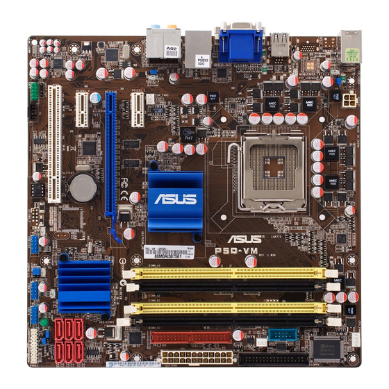
Page 22: Motherboard Overview
Motherboard overview 1.5.1 Motherboard layout Refer to 1.10 Connectors for more information about rear panel connectors and internal connectors. 1-10 Chapter 1: Product introduction... -
Page 23: Layout Contents
USB connectors (10-1 pin USB78; USB910; USB1112) 1-37 USB device wake-up (3-pin USBPW1-4; USB7-10; USB1112) 1-29 Optical drive audio connector (4-pin CD) 1-40 Front panel audio connector (10-1 pin AAFP) 1-40 Digital audio connector (4-1 pin SPDIF_OUT) 1-39 ASUS P5Q-VM 1-11... -
Page 24: Placement Direction
1.5.3 Placement direction When installing the motherboard, make sure that you place it into the chassis in the correct orientation. The edge with external ports goes to the rear part of the chassis as indicated in the image below. 1.5.4 Screw holes Place eight (8) screws into the holes indicated by circles to secure the motherboard to the chassis. -
Page 25: Central Processing Unit (Cpu)
ASUS will shoulder the cost of repair only if the damage is shipment/transit-related. • Keep the cap after installing the motherboard. ASUS will process Return Merchandise Authorization (RMA) requests only if the motherboard comes with the cap on the LGA775 socket. -
Page 26: Installing The Cpu
1.6.1 Installing the CPU To install a CPU: Locate the CPU socket on the motherboard. Before installing the CPU, make sure that the cam box is facing towards you and the load lever is on your left. Press the load lever with your Retention tab thumb (A), then move it to the left (B) until it is released from the... - Page 27 The Thermal Interface Material is toxic and inedible. If it gets into your eyes or touches your skin, ensure to wash it off immediately, and seek professional medical help. To prevent contaminating the paste, DO NOT spread the paste with your finger directly. ASUS P5Q-VM 1-15...
- Page 28 Close the load plate (A), then push the load lever (B) until it snaps into the retention tab. The motherboard supports Intel ® LGA775 processors with the Intel ® Enhanced Memory 64 Technology (EM64T), Enhanced Intel SpeedStep Technology ® (EIST), and Hyper-Threading Technology. 1-16 Chapter 1: Product introduction...
-
Page 29: Installing The Cpu Heatsink And Fan
Push down two fasteners at a time in a diagonal sequence to secure the heatsink and fan assembly in place. Orient the heatsink and fan assembly such that the CPU fan cable is closest to the CPU fan connector. ASUS P5Q-VM 1-17... -
Page 30: Uninstalling The Cpu Heatsink And Fan
Connect the CPU fan cable to the connector on the motherboard labeled CPU_FAN. DO NOT forget to connect the CPU fan connector! Hardware monitoring errors can occur if you fail to plug this connector. 1.6.3 Uninstalling the CPU heatsink and fan To uninstall the CPU heatsink and fan: Disconnect the CPU fan cable from the connector on the motherboard. -
Page 31: System Memory
240-pin footprint compared to the 184-pin DDR DIMM. DDR2 DIMMs are notched differently to prevent installation on a DDR DIMM socket. The figure illustrates the location of the DDR2 DIMM sockets: Channel Sockets Channel A DIMM_A1 and DIMM_A2 Channel B DIMM_B1 and DIMM_B2 ASUS P5Q-VM 1-19... -
Page 32: Memory Configurations
1.7.2 Memory configurations You may install 512 MB, 1 GB, 2 GB, and 4 GB non-ECC, unbuffered, DDR2 DIMMs into the DIMM sockets. • Due to chipset behavior, to obtain memory frequency higher than DDR2 800, you can manually adjust DRAM Frequency in BIOS settings. Refer to 2.4 Ai Tweaker menu for details. - Page 33 Heat-Sink Package • • G.SKILL F2-6400CL6D-8GBNQ 8192MB(Kit of 2) Heat-Sink Package 6-6-6-18 • • • G.SKILL F2-6400PHU2-2GBNR 1024MB Heat-Sink Package • • • GEIL GB22GB6400C4DC 2048MB(Kit of 2) GL2L64M088BA30EB • • • (continued on the next page) ASUS P5Q-VM 1-21...
- Page 34 GEIL GB22GB6400C5DC 2048MB(Kit of 2) GL2L64M088BA30EB 5-5-5-15 • • • GEIL GB24GB6400C4DC 4096MB(Kit of 2) GL2L128M88BA25AB 4-4-4-12 • • • GEIL GB24GB6400C4QC 4096MB(Kit of 4) GL2L64M088BA30EB • • • GEIL GB24GB6400C5DC 4096MB(Kit of 2) GL2L128M88BA25AB 5-5-5-15 • • • GEIL GB24GB6400C5QC 4096MB(Kit of 2) GL2L64M088BA30EB...
-
Page 35: Memory Configuration
Dual-channel memory configuration. • C*: Supports four modules inserted into both the yellow and black slots as two pairs of Dual-channel memory configuration. Visit the ASUS website for the latest DDR2-1066/800/667MHz QVL. ASUS P5Q-VM 1-23... -
Page 36: Installing A Dimm
1.7.3 Installing a DIMM Make sure to unplug the power supply before adding or removing DIMMs or other system components. Failure to do so may cause severe damage to both the motherboard and the components. To install a DIMM DDR2 DIMM notch Unlock a DDR2 DIMM socket by pressing the retaining clips outward. -
Page 37: Expansion Slots
IRQ” or that the cards do not need IRQ assignments. Otherwise, conflicts will arise between the two PCI groups, making the system unstable and the card inoperable. Refer to the table on the next page for details. ASUS P5Q-VM 1-25... -
Page 38: Interrupt Assignments
1.8.3 Interrupt assignments Priority Standard function System timer Keyboard controller – Re-direct to IRQ#9 IRQ holder for PCI steering* Communications port (COM1)* IRQ holder for PCI steering* Floppy disk controller IRQ holder for PCI steering* System CMOS/Real Time Clock IRQ holder for PCI steering* IRQ holder for PCI steering* IRQ holder for PCI steering* PS/2 compatible mouse port*... -
Page 39: Pci Slot
This motherboard has a PCI Express 2.0 x16 slot that supports PCI Express 2.0 x16 graphics cards complying with the PCI Express specifications. Refer to the figure below for the location of the slot. PCI slot PCIe x1 slot PCIe 2.0 x16 slot PCIe x1 slot ASUS P5Q-VM 1-27... -
Page 40: Jumpers
Jumpers Clear RTC RAM (3-pin CLRTC) This jumper allows you to clear the Real Time Clock (RTC) RAM in CMOS. You can clear the CMOS memory of date, time, and system setup parameters by erasing the CMOS RTC RAM data. The onboard button cell battery powers the RAM data in CMOS, which include system setup information such as system passwords. - Page 41 500mA on the +5VSB lead for each USB port; otherwise, the system would not power up. • The total current consumed must NOT exceed the power supply capability (+5VSB) whether under normal condition or in sleep mode. ASUS P5Q-VM 1-29...
-
Page 42: 1.10 Connectors
1.10 Connectors 1.10.1 Rear panel connectors PS/2 keyboard / mouse combo port. This port is for a PS/2 keyboard or mouse. Video Graphics Adapter (VGA) port. This 15-pin port is for a VGA monitor or other VGA-compatible devices. LAN (RJ-45) port. This port allows Gigabit connection to a Local Area Network (LAN) through a network hub. - Page 43 Windows Display Settings menu. ® • Due to the Intel driver issue, some monitor resolution settings will ® lead to monitor overscan or underscan. Refer to the next page for the troubleshooting on monitor overscan/underscan problem ASUS P5Q-VM 1-31...
- Page 44 Playback of HD DVD and Blu-Ray Discs • The speed and bandwidth of the CPU/Memory, DVD player, and drivers will affect the playback quality. Following is a configuration example for your reference. Using the CPU/Memory of higher speed and bandwidth with the higher-version DVD player and drivers will upgrade the playback quality.
- Page 45 Media Accelerator Driver icon and click Graphics Properties. Click Display Settings and select a Screen Resolution. Click Apply. Or you can click Aspect Ratio Options (if available). Move the Horizontal and Vertical sliders and then click Apply. ASUS P5Q-VM 1-33...
-
Page 46: Internal Connectors
1.10.2 Internal connectors Floppy disk drive connector (34-1 pin FLOPPY) This connector is for the provided floppy disk drive (FDD) signal cable. Insert one end of the cable to this connector, then connect the other end to the signal connector at the back of the floppy disk drive. Pin 5 on the connector is removed to prevent incorrect cable connection when using a FDD cable with a covered Pin 5. - Page 47 Ultra DMA cable connector. This prevents incorrect insertion when you connect the IDE cable. • Use the 80-conductor IDE cable for Ultra DMA 133/100/66 IDE devices. If any device jumper is set as “Cable-Select,” make sure all other device jumpers have the same setting. ASUS P5Q-VM 1-35...
- Page 48 ICH10 Serial ATA connectors [red] (7-pin SATA1-6) These connectors are for the Serial ATA signal cables for Serial ATA hard disk drives and optical disc drives. • These connectors are set to Standard IDE mode by default. In Standard IDE mode, you can connect Serial ATA boot/data hard disk drives to these connectors.
- Page 49 This connector is for a serial (COM) port. Connect the serial port module cable to this connector, then install the module to a slot opening at the back of the system chassis. The serial port module is purchased separately. ASUS P5Q-VM 1-37...
- Page 50 DO NOT forget to connect the fan cables to the fan connectors. Insufficient air flow inside the system may damage the motherboard components. These are not jumpers! Do not place jumper caps on the fan connectors! Only the CPU_FAN and CHA_FAN 1 connectors support the ASUS Fan Xpert feature. 1-38...
- Page 51 Remove the jumper caps only when you intend to use the chassis intrusion detection feature. Digital audio connector (4-1 pin SPDIF_OUT) This connector is for an additional Sony/Philips Digital Interface (S/PDIF) port(s). The S/PDIF out cable is purchased separately. ASUS P5Q-VM 1-39...
- Page 52 Front panel audio connector (10-1 pin AAFP) This connector is for a chassis-mounted front panel audio I/O module that supports either HD Audio or legacy AC`97 audio standard. Connect one end of the front panel audio I/O module cable to this connector. •...
- Page 53 • If you are uncertain about the minimum power supply requirement for your system, refer to the Recommended Power Supply Wattage Calculator at http://support.asus.com/PowerSupplyCalculator/PSCalculator. aspx?SLanguage=en-us for details. ASUS P5Q-VM 1-41...
-
Page 54: System Panel Connector
12. System panel connector (20-8 pin PANEL) This connector supports several chassis-mounted functions. • System power LED (2-pin PLED) This 2-pin connector is for the system power LED. Connect the chassis power LED cable to this connector. The system power LED lights up when you turn on the system power, and blinks when the system is in sleep mode. -
Page 55: 1.11 Starting Up For The First Time
One continuous beep followed by three No VGA detected short beeps One continuous beep followed by four Hardware component failure short beeps At power on, hold down the <Delete> key to enter the BIOS Setup. Follow the instructions in Chapter 2. ASUS P5Q-VM 1-43... -
Page 56: 1.12 Turning Off The Computer
1.12 Turning off the computer 1.12.1 Using the OS shut down function If you are using Windows Vista: ® Click the Start button and then select Shut Down. The power supply should turn off after Windows shuts down. ® If you are using Windows ®... -
Page 57: Chapter 2: Bios Setup
This chapter tells how to change the system settings through the BIOS Setup menus. Detailed descriptions of the BIOS parameters are also provided. Chapter 2: BIOS setup... -
Page 58: Managing And Updating Your Bios
ASUS Update (Updates the BIOS in Windows environment.) ® ASUS EZ Flash 2 (Updates the BIOS using a floppy disk or USB flash disk.) ASUS AFUDOS (Updates the BIOS using a bootable floppy disk) ASUS CrashFree BIOS 3 (Updates the BIOS using a bootable floppy disk, USB flash disk or the motherboard support DVD when the BIOS file fails or gets corrupted.) - Page 59 To update the BIOS through the Internet: desktop by clicking Start Launch the ASUS Update utility from the Windows ® > Programs > ASUS > ASUSUpdate > ASUSUpdate. The ASUS Update main window appears. Select Update BIOS from the Select the ASUS FTP site nearest...
- Page 60 To update the BIOS through a BIOS file: desktop by clicking Start Launch the ASUS Update utility from the Windows ® > Programs > ASUS > ASUSUpdate > ASUSUpdate. The ASUS Update main window appears. Select Update BIOS from a file option from the drop-down menu, then click Next.
-
Page 61: Creating A Bootable Floppy Disk
Right-click Floppy Disk Drive then click Format to display the Format 3 1/2 Floppy dialog box. d. Select the Create an MS-DOS startup disk check box. e. Click Start. Copy the original or the latest motherboard BIOS file to the bootable floppy disk. ASUS P5Q-VM... -
Page 62: Asus Ez Flash 2 Utility
2.1.3 ASUS EZ Flash 2 utility The ASUS EZ Flash 2 feature allows you to update the BIOS without having to go through the long process of booting from a floppy disk and using a DOS-based utility. The EZ Flash 2 utility is built-in the BIOS chip so it is accessible by pressing <Alt>... -
Page 63: Afudos Utility
The utility returns to the DOS prompt after copying the current BIOS file. Updating the BIOS file To update the BIOS file using the AFUDOS utility: Visit the ASUS website (www.asus.com) and download the latest BIOS file for the motherboard. Save the BIOS file to a bootable floppy disk. ASUS P5Q-VM... - Page 64 A:\>afudos /iP5QVM.ROM The utility verifies the file and starts updating the BIOS. A:\>afudos /iP5QVM.ROM AMI Firmware Update Utility - Version 1.19(ASUS V2.07(02.11.24BB)) Copyright (C) 2002 American Megatrends, Inc. All rights reserved. WARNING!! Do not turn off power during flash BIOS Reading file ..
-
Page 65: Asus Crashfree Bios 3 Utility
2.1.5 ASUS CrashFree BIOS 3 utility The ASUS CrashFree BIOS 3 is an auto recovery tool that allows you to restore the BIOS file when it fails or gets corrupted during the updating process. You can update a corrupted BIOS file using the motherboard support DVD, the floppy disk, or the USB flash disk that contains the updated BIOS file. -
Page 66: Bios Setup Program
The BIOS setup screens shown in this section are for reference purposes only, and may not exactly match what you see on your screen. • Visit the ASUS website (www.asus.com) to download the latest BIOS file for this motherboard. 2-10... -
Page 67: Bios Menu Screen
At the bottom right corner of a menu screen are the navigation keys for that particular menu. Use the navigation keys to select items in the menu and change the settings. The navigation keys may differ from one screen to another. ASUS P5Q-VM 2-11... -
Page 68: Menu Items
2.2.4 Menu items The highlighted item on the menu bar displays the specific items for that Use [ENTER], [TAB], or System Time [11:56:54] [SHIFT-TAB] to select menu. For example, selecting Main System Date [Tue 07/15/2008] a field. Floppy Diskette A [1.44M, 2.5 in.] Use [+] or [-] to SATA1... -
Page 69: Main Menu
Allows you to set the system time. 2.3.2 System Date [Day xx/xx/xxxx] Allows you to set the system date. 2.3.3 Legacy Diskette A [1.44M, 2.5 in.] Sets the type of floppy drive installed. Configuration options: [Disabled] [720K , 2.5 in.] [1.44M, 2.5 in.] ASUS P5Q-VM 2-13... -
Page 70: Sata 1-6
2.3.4 SATA 1–6 While entering Setup, the BIOS automatically detects the presence of Serial ATA devices. There is a separate sub-menu for each SATA device. Select a device item then press <Enter> to display the SATA device information. BIOS SETUP UTILITY Main SATA 1 Select the type of... -
Page 71: Storage Configuration
Serial ATA features that increases storage performance on random workloads by allowing the drive to internally optimize the order of commands. • AHCI mode is not supported in Windows ® ASUS P5Q-VM 2-15... -
Page 72: Ahci Configuration
Hard Disk Write Protect [Disabled] Disables or enables device write protection. This will be effective only if the device is accessed through BIOS. Configuration option: [Disabled] [Enabled] IDE Detect Time Out (Sec) [35] Selects the time out value for detecting ATA/ATAPI devices. Configuration options: [0] [5] [10] [15] [20] [25] [30] [35] 2.3.6 AHCI Configuration... -
Page 73: System Information
Usable Size : 2048MB Select Item General Help Save and Exit Exit v02.61 (C)Copyright 1985-2008, American Megatrends, Inc. Bios Information Displays the auto-detected BIOS information. Processor Displays the auto-detected CPU specification. System Memory Displays the auto-detected system memory. ASUS P5Q-VM 2-17... -
Page 74: Ai Tweaker Menu
Ai Tweaker menu The Ai Tweaker menu items allow you to configure overclocking-related items. Take caution when changing the settings of the Ai Tweaker menu items. Incorrect field values can cause the system to malfunction. The default values of the following items vary depending on the CPU and memory modules you install on the motherboard. - Page 75 The following table shows the variation of options according to FSB Frequency settings. DRAM Frequency (MHz) Auto 1002 1064 1111 1200 1600 • • • • • 1333 • • • • • 1066 • • • • • • • ASUS P5Q-VM 2-19...
- Page 76 Selecting a very high DRAM frequency may cause the system to become unstable! If this happens, revert to the default setting. DRAM Timing Control [Auto] Configuration options: [Auto] [Manual] The following sub-items apprear only when you set the DRAM Timing •...
- Page 77 Ai Clock Twister [Auto] Allows you to set the DRAM performance. Set this item to [Light] or [Lighter] to enhance DRAM compatibility, or [Strong] or [Stronger] to accelerate DRAM performance. Configuration options: [Auto] [Lighter] [Light] [Moderate] [Strong] [Stronger] ASUS P5Q-VM 2-21...
- Page 78 Ai Transaction Booster [Auto] Allows you to set the system performance. Configuration options: [Auto] [Manual] The following two sub-items appear only when you set the Ai Transaction Booster item to [Manual]. Common Performance Level [05] Set this item to a higher level for better compatibility or a lower level for better performance.
- Page 79 Set to [Disabled] to enhance FSB overclocking ability or [Auto] for EMI control. Configuration options: [Auto] [Disabled] PCIE Spread Spectrum [Auto] Set to [Disabled] to enhance PCIE overclocking ability or [Auto] for EMI control. Configuration options: [Auto] [Disabled] ASUS P5Q-VM 2-23...
- Page 80 CPU Clock Skew [Auto] Configuration options: [Auto] [Normal] [Delay 100ps] [Delay 200ps]–[Delay 1500ps] NB Clock Skew [Auto] Configuration options: [Auto] [Normal] [Delay 100ps] [Delay 200ps]–[Delay 1500ps] CPU Margin Enhancement [Optimized] Configuration options: [Optimized] [Compatible] [Performance Mode] 2-24 Chapter 2: BIOS setup...
-
Page 81: Advanced Menu
Select Item C1E Support [Enabled] Change Option Intel(R) Virtualization Tech [Enabled] General Help CPU TM Function [Enabled] Save and Exit Execute-Disable Bit [Enabled] Exit Intel(R) SpeedStep(TM) Tech [Enabled] Intel(R) C-STATE Tech [Enabled] v02.61 (C)Copyright 1985-2008, American Megatrends, Inc. ASUS P5Q-VM 2-25... - Page 82 CPU Ratio Setting [Auto] Allows you to adjust the ratio between CPU Core Clock and FSB Frequency. Use the <+> and <-> keys to adjust the value. The values may vary depending on the The values may vary depending on the CPU installed.
-
Page 83: Chipset
Allows you to set the GMCH Protected Audio Video Path (PAVP) BIOS support. Configuration options: [Disabled] [Lite Mode] [Paranoid] DVMT Memory [256MB] Configuration options: [128MB] [256MB] [Maximum DVMT] The [Maximum DVMT] option appears only when you install DIMM modules more than 1 GB. ASUS P5Q-VM 2-27... -
Page 84: Onboard Devices Configuration
This motherboard supports Intel DVMT 5.0 Technology whose maximum ® graphics memory size in total varies with the system memory size in total and the operating system. Refer to the following table for details. Maximum Total Graphics Memory System Memory Windows Windows Vista™... -
Page 85: Usb Configuration
The USB Devices Enabled item shows the auto-detected values. If no USB device is detected, the item shows None. USB Functions [Enabled] Allows you to enable or disable the USB Host Controllers. Configuration options: [Disabled] [Enabled] The following items appear only when you set USB Functions to [Enabled]. ASUS P5Q-VM 2-29... -
Page 86: Pcipnp
USB 2.0 Controller [Enabled] Allows you to enable or disable the USB 2.0 controller. Configuration options: [Enabled] [Disabled] USB 2.0 Controller Mode [HiSpeed] Allows you to set the USB 2.0 controller mode to HiSpeed (480 Mbps) or FullSpeed (12 Mbps). Configuration options: [FullSpeed] [HiSpeed] The USB 2.0 Controller Mode item appears only when you enable the USB 2.0 Controller. -
Page 87: Power Menu
Allows you to enable or disable the Advanced Configuration and Power Interface (ACPI) support in the Advanced Programmable Interrupt Controller (APIC). When set to [Enabled], the ACPI APIC table pointer is included in the RSDT pointer list. Configuration options: [Disabled] [Enabled] ASUS P5Q-VM 2-31... -
Page 88: Apm Configuration
2.6.5 APM Configuration BIOS SETUP UTILITY Power APM Configuration <Enter> to select whether or not to Restore on AC Power Loss [Power Off] restart the system after AC power loss. Power On By RTC Alarm [Disabled] Power On By External Modems [Disabled] Power On By PCI Devices [Disabled]... -
Page 89: Hardware Monitor
[N/A]. CPU Q-Fan Control [Enabled] Allows you to enable or disable the CPU Q-fan control feature. Configuration options: [Disabled] [Enabled] The following item appears only when you enable the CPU Q-Fan Control item. ASUS P5Q-VM 2-33... - Page 90 CPU Fan Profile [Standard] Allows you to set the appropriate performance level of the ASUS Q-Fan. When set to [Standard], the CPU fan automatically adjusts depending on the CPU temperature. Set this item to [Silent] to minimize fan speed for quiet CPU fan operation, or [Turbo] to achieve maximum CPU fan speed.
-
Page 91: Boot Menu
These items specify the boot device priority sequence from the available devices. The number of device items that appears on the screen depends on the number of devices installed in the system. Configuration options: [1st FLOPPY DRIVE] [Hard Drive] [ATAPI CD-ROM] [Disabled] ASUS P5Q-VM 2-35... -
Page 92: Boot Settings Configuration
This allows you to enable or disable the full screen logo display feature. Configuration options: [Disabled] [Enabled] Set this item to [Enabled] to use the ASUS MyLogo 2™ feature. AddOn ROM Display Mode [Force BIOS] Sets the display mode for option ROM. -
Page 93: Security
If you forget your BIOS password, you can clear it by erasing the CMOS Real Time Clock (RTC) RAM. See section 1.9 Jumpers for information on how to erase the RTC RAM. After you have set a supervisor password, the other items appear to allow you to change other security settings. ASUS P5Q-VM 2-37... -
Page 94: Change User Password
BIOS SETUP UTILITY Boot Security Settings <Enter> to change password. Supervisor Password : Installed <Enter> again to User Password : Installed disabled password. Change Supervisor Password User Access Level [Full Access] Change User Password Clear User Password Password Check [Setup] User Access Level [Full Access] This item allows you to select the access restriction to the Setup items. -
Page 95: Tools Menu
2.8.1 ASUS EZ Flash 2 Allows you to run ASUS EZ Flash 2. When you press <Enter>, a confirmation message appears. Use the left/right arrow key to select between [Yes] or [No], then press <Enter> to confirm your choice. Please see section 2.1.3 ASUS EZ Flash 2 utility for details. -
Page 96: Express Gate
2.8.2 Express Gate Allows you to enable or disable the ASUS Express Gate feature. The ASUS Express Gate feature is a unique instant-on environment that provides quick access to the Internet browser and Skype. Configuration options: [Disabled] [Enabled] [Enabled] Enter OS Timer [10 Seconds] Sets countdown duration that the system waits at the Express Gate’s first... -
Page 97: Asus O.c. Profile
2.8.3 ASUS O.C. Profile This item allows you to store or load multiple BIOS settings. BIOS SETUP UTILITY Tools O.C. PROFILE Configuration Save BIOS settings O.C. Profile 1 Status : Not Installed to Profile 1 O.C. Profile 2 Status : Not Installed... -
Page 98: Ai Net 2
2.8.4 AI Net 2 BIOS SETUP UTILITY Tools Realtek Check LAN AI NET 2 cable during POST. Pair Status Length It will take 3 to 10 seconds to diagnose Check Realtek LAN cable [Disabled] LAN cable. Select Screen Select Item Change Field Enter Go to Sub Screen General Help... -
Page 99: Exit Menu
Setup menus. When you select this option or if you press <F5>, a confirmation window appears. Select Ok to load default values. Select Exit & Save Changes or make other changes before saving the values to the non-volatile RAM. ASUS P5Q-VM 2-43... - Page 100 2-44 Chapter 2: BIOS setup...
-
Page 101: Chapter 3: Software Support
This chapter describes the contents of the support DVD that comes with the motherboard package. Chapter 3: Software support... -
Page 102: Installing An Operating System
The contents of the support DVD are subject to change at any time without notice. Visit the ASUS website (www.asus.com) for updates. 3.2.1 Running the support DVD Place the support DVD to the optical drive. -
Page 103: Drivers Menu
The drivers menu shows the available device drivers if the system detects installed devices. Install the necessary drivers to activate the devices. ASUS InstAll-Installation Wizard for Anti-Virus and Drivers Utility Installs anti-virus software and all of the drivers through the Installation Wizard. -
Page 104: Utilities Menu
Click to display the previous screen ASUS InstAll-Installation Wizard for Utilities Installs all of the utilities through the Installation Wizard. ASUS PC Probe II This smart utility monitors the fan speed, CPU temperature, and system voltages, and alerts you of any detected problems. This utility helps you keep your computer in healthy operating condition. - Page 105 ASUS Update The ASUS Update utility allows you to update the motherboard BIOS in Windows ® environment. This utility requires an Internet connection either through a network or an Internet Service Provider (ISP). ASUS Express Gate Installer Installs the ASUS Express Gate application.
-
Page 106: Manual Menu
Reader before opening a user manual file. ® ® 3.2.5 ASUS Contact information Click the Contact tab to display the ASUS contact information. You can also find this information on the inside front cover of this user guide. Chapter 3: Software support... -
Page 107: Other Information
The icons on the top right corner of the screen give additional information on the motherboard and the contents of the support DVD. Click an icon to display the specified information. Motherboard Info Displays the general specifications of the motherboard. Browse this DVD Displays the support DVD contents in graphical format. ASUS P5Q-VM... -
Page 108: Technical Support Form
Technical support Form Displays the ASUS Technical Support Request Form that you have to fill out when requesting technical support. Filelist Displays the contents of the support DVD and a brief description of each in text format. Chapter 3: Software support... -
Page 109: Asus Express Gate
ASUS Express Gate ASUS Express Gate is an instant-on environment that gives you quick access to the Internet. Within a few seconds of powering on your computer, you will be at the Express Gate menu where you can start the web browser, Skype, or other Express Gate softwares. - Page 110 Select the target disk volume for you to install Express Gate. If you have multiple volumes and OS installed in your hard drive, it is recommended to install Express Gate in Volume C. Click Next to continue. Follow the screen instructions to complete installation.
- Page 111 Enter Boot selection pop-up In the Express Gate Environment: Function <Alt> + <Tab> Switch between softwares <Ctrl> + <Alt> + <Del> Bring up Power-Off dialog box <Ctrl> + <Alt> + <Print Screen> Save screen snapshot as picture to file ASUS P5Q-VM 3-11...
-
Page 112: Using The Configuration Panel
Using the Configuration Panel Use the configuration panel to change various Express Gate settings. Click on an icon to open a particular configuration tool. The following tools are available: Date and Time: set current date and time as well as time zone. •... -
Page 113: Using The Launchbar
USB drive. If a USB device is detected, the icon contains a green arrow. ASUS Express Gate supports file uploading from SATA HDDs, ODDs and USB drive and downloading to USB drives only. Shows network status; click to configure network. - Page 114 Click to change LaunchBar options (auto-hide, docking position, etc). Click to show the “ASUS Utility” panel (if supported). Click to show “About Express Gate.” Click to open Express Gate Help. Click to bring up power options window to boot to OS, restart or power down.
- Page 115 LAN port. Then enter the username and password for your dial-up account. Click OK to enable xDSL/cable dial-up and establish the PPPoE connection. When PPPoE is enabled, the port it uses will automatically be unchecked and grayed out. ASUS P5Q-VM 3-15...
-
Page 116: Using The Photo Manager
Shows user- created image album(s) Image control bar ASUS Express Gate supports HDDs connected to motherboard chipset- controlled onboard SATA ports only. All onboard extended SATA ports and external SATA ports are NOT supported. 3-16 Chapter 3: Software support... -
Page 117: Updating Express Gate
Express Gate software will be released regularly, adding refinements or new applications. You can find original version of the software on the support DVD or download new versions from the ASUS support website. To update Express Gate Double-click the Express Gate setup file to start software update. - Page 118 3-18 Chapter 3: Software support...
Need help?
Do you have a question about the P5Q-VM - Motherboard - Micro ATX and is the answer not in the manual?
Questions and answers