Table of Contents
Advertisement
Quick Links
Advertisement
Table of Contents

Related Manuals for Asus P5L-MX IPAT


Summary of Contents for Asus P5L-MX IPAT
- Page 1 P5L-MX/ IPAT...
- Page 2 Product warranty or service will not be extended if: (1) the product is repaired, modified or altered, unless such repair, modification of alteration is authorized in writing by ASUS; or (2) the serial number of the product is defaced or missing.
-
Page 3: Table Of Contents
Contents Notices ....................vi Safety information ................vii About this guide .................viii Typography ..................ix P5L-MX/IPAT specifications summary ..........x Chapter 1: Product introduction Welcome! ................1-2 Package contents ..............1-2 Special features ..............1-2 Before you proceed .............. 1-4 Motherboard overview ............1-5 1.5.1 Placement direction .......... - Page 4 Contents 1.10 Connectors ................. 1-24 1.10.1 Rear panel connectors .......... 1-24 1.10.2 Internal connectors ..........1-25 Chapter 2: BIOS setup Managing and updating your BIOS ........2-2 2.1.1 Creating a bootable floppy disk ......2-2 2.1.2 AFUDOS utility ............2-3 2.1.3 AFUWIN utility ............
- Page 5 Running the support CD .......... 3-2 3.2.2 Drivers menu ............3-3 3.2.3 Utilities menu ............3-4 3.2.4 Manuals menu ............3-6 3.2.5 ASUS Contact information ........3-6 Appendix: CPU features Intel EM64T ................. A-2 ® Using the Intel EM64T feature ..........A-2 ®...
-
Page 6: Notices
Notices Federal Communications Commission Statement This device complies with Part 15 of the FCC Rules. Operation is subject to the following two conditions: • This device may not cause harmful interference, and • This device must accept any interference received including interference that may cause undesired operation. -
Page 7: Safety Information
Safety information Electrical safety • To prevent electrical shock hazard, disconnect the power cable from the electrical outlet before relocating the system. • When adding or removing devices to or from the system, ensure that the power cables for the devices are unplugged before the signal cables are connected. -
Page 8: About This Guide
Refer to the following sources for additional information and for product and software updates. ASUS websites The ASUS website provides updated information on ASUS hardware and software products. Refer to the ASUS contact information. Optional documentation Your product package may include optional documentation, such as warranty flyers, that may have been added by your dealer. -
Page 9: Typography
Conventions used in this guide To make sure that you perform certain tasks properly, take note of the following symbols used throughout this manual. DANGER/WARNING: Information to prevent injury to yourself when trying to complete a task. CAUTION: Information to prevent damage to the components when trying to complete a task. -
Page 10: P5L-Mx/Ipat Specifications Summary
P5L-MX/IPAT specifications summary LGA775 socket for Intel Core™2 Extreme / Core™2 Duo / ® Pentium D / Pentium 4 / Celeron D Processors ® ® ® Compatible with Intel 06/05B/05A processors ® Supports Intel next generation 65nm processors ® Supports Intel Enhanced Memory 64 Technology (EM64T), ®... - Page 11 ATX power supply (with 24-pin and 4-pin 12 V plugs) Requirement Form Factor Micro-ATX form factor: 9.6 in x 8 in (24.5cm x 20.3cm) Support CD Device drivers contents ASUS PC Probe II ASUS update ASUS Screensaver *Specifications are subject to change without notice.
-
Page 13: Chapter 1: Product Introduction
This chapter describes the motherboard features and the new technologies it supports. Product introduction... -
Page 14: Welcome
® The motherboard delivers a host of new features and latest technologies, making it another standout in the long line of ASUS quality motherboards! Before you start installing the motherboard, and hardware devices on it, check the items in your package with the list below. - Page 15 The motherboard supports the Serial ATA technology through the Serial ATA interfaces and the Intel ICH7 chipset. The SATA specification allows ® for thinner, more flexible cables with lower pin count, reduced voltage requirement, and up to 300 MB/s data transfer rate. ASUS P5L-MX/IPAT...
-
Page 16: Before You Proceed
Before you proceed Take note of the following precautions before you install motherboard components or change any motherboard settings. • Unplug the power cord from the wall socket before touching any component. • Use a grounded wrist strap or touch a safely grounded object or to a metal object, such as the power supply case, before handling components to avoid damaging them due to static electricity •... -
Page 17: Motherboard Overview
1.5.2 Screw holes Place six (6) screws into the holes indicated by circles to secure the motherboard to the chassis. Do not overtighten the screws! Doing so can damage the motherboard. Place this side towards the rear of the chassis ASUS P5L-MX/IPAT... -
Page 18: Motherboard Layout
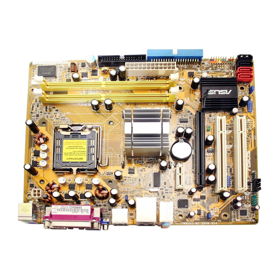
1.5.3 Motherboard layout 20.3cm (8in) CPU_FAN PS/2KBMS T : Mouse B: Keyboard Super I/O ATX12V LGA775 CHA_FAN1 USB12 USBPW1234 LAN_USB34 Intel GMCH945G ICS PRS552 AUDIO CR2032 3V PCIEX1_1 Lithium Cell Attansic CMOS Power PCIEX16 SB_PWR USBPW5678 PCI1 Intel ICH7 USB56 PCI2 AD1986A BIOS... -
Page 19: Central Processing Unit (Cpu)
Contact your retailer immediately if the PnP cap is missing, or if you see any damage to the PnP cap/socket pins/motherboard components. ASUS will shoulder the cost of repair only if the damage is shipment/ transit-related. •... - Page 20 Press the load lever with your thumb (A) and move it to the left (B) until it is released from the retention tab. PnP Cap Retention tab Load lever This side of the cam box should face you. To prevent damage to the socket pins, do not remove the PnP cap unless you are installing a CPU.
- Page 21 LGA775 processors with the Intel ® ® Enhanced Memory 64 Technology (EM64T), Enhanced Intel SpeedStep ® Technology (EIST), and Hyper-Threading Technology. If you install a dual-core CPU, make sure to connect the chassis fan cable to CHA_FAN connector for system stability. ASUS P5L-MX/IPAT...
-
Page 22: Installling The Cpu Heatsink And Fan
1.6.2 Installling the CPU heatsink and fan The Intel Core™2 Extreme/Core™2 Duo/Pentium D/Pentium 4 and ® ® ® Celeron D processors require a specially designed heatsink and fan ® assembly to ensure optimum thermal condition and performance. • Install the motherboard to the chassis before you install the CPU fan and heatsink assembly •... - Page 23 CPU_FAN. CPU_FAN CPU FAN PWM CPU FAN IN CPU FAN PWR P5L-MX/IPAT CPU Fan Connector Do not forget to connect the CPU fan connector! Hardware monitoring errors can occur if you fail to plug this connector. ASUS P5L-MX/IPAT 1-11...
-
Page 24: Uninstalling The Cpu Heatsink And Fan
1.6.3 Uninstalling the CPU heatsink and fan To uninstall the CPU heatsink and fan: Disconnect the CPU fan cable from the connector on the motherboard. Rotate each fastener counterclockwise. Pull up two fasteners at a time in a diagonal sequence to disengage the heatsink and fan assembly from the motherboard. - Page 25 Rotate each fastener clockwise to reset the orientation. Narrow end of the groove The narrow end of the groove should point outward after resetting. (The photo shows the groove shaded for emphasis.) ASUS P5L-MX/IPAT 1-13...
-
Page 26: System Memory
System memory 1.7.1 Overview The motherboard comes with two Double Data Rate 2 (DDR2) Dual Inline Memory Modules (DIMM) sockets. A DDR2 module has the same physical dimensions as a DDR DIMM but has a 240-pin footprint compared to the 184-pin DDR DIMM. DDR2 DIMMs are notched differently to prevent installation on a DDR DIMM socket. - Page 27 32-bit version OS. The excess memory installation will not cause any usage problem, but it will not give users the benefit of manipulating this excess memory space. Visit the ASUS FAQ site for further explanation: http://support.asus.com/faq/faq.aspx?SLanguage=en-us Under General Search, make the selections as shown, then click Search.
-
Page 28: Ddr2 Qualified Vendors List
DDR2 Qualified Vendors List The following table lists the memory modules that have been tested and qualified for use with this motherboard. Visit the ASUS website (www.asus. com) for the latest DDR2 DIMM modules for this motherboard. DDR2 667 Qualified Vendors List... - Page 29 DS - Double Sided DIMM Support: A - supports one module inserted into either slot, in a Single-channel memory configuration. B - supports on pair of modules inserted into either the yellow slots as one pair of Dual-channel memory configuration. ASUS P5L-MX/IPAT 1-17...
-
Page 30: Installing A Dimm
1.7.4 Installing a DIMM Unplug the power supply before adding or removing DIMMs or other system components. Failure to do so can cause severe damage to both the motherboard and the components. To install a DIMM: DDR2 DIMM notch Unlock a DIMM socket by pressing the retaining clips outward. -
Page 31: Expansion Slots
Turn on the system and change the necessary BIOS settings, if any. See Chapter 2 for information on BIOS setup. Assign an IRQ to the card. Refer to the tables on the next page. Install the software drivers for the expansion card. ASUS P5L-MX/IPAT 1-19... -
Page 32: Interrupt Assignments
1.8.3 Interrupt assignments Standard interrupt assignments Standard Function System Timer Keyboard Controller Re-direct to IRQ#9 Communications Port (COM1)* IRQ holder for PCI steering* Floppy Disk Controller Printer Port (LPT1)* System CMOS/Real Time Clock IRQ holder for PCI steering* IRQ holder for PCI steering* IRQ holder for PCI steering* PS/2 Compatible Mouse Port* Numeric Data Processor... -
Page 33: Pci Slots
1.8.6 PCI Express x1 This motherboard supports PCI Express x1 network cards, SCSI cards and other cards that comply with the PCI Express specifications. The figure shows a network card installed on the PCI Express x1 slot. ASUS P5L-MX/IPAT 1-21... -
Page 34: Jumpers
Jumpers Clear RTC RAM (CLRTC) This jumper allows you to clear the Real Time Clock (RTC) RAM in CMOS. You can clear the CMOS memory of date, time by erasing the CMOS RTC RAM data. The onboard button cell battery powers the RAM data in CMOS. - Page 35 500 mA on the +5VSB lead for each USB port; otherwise, the system would not power up. • The total current consumed must NOT exceed the power supply capability (+5VSB) whether under normal condition or in sleep mode. ASUS P5L-MX/IPAT 1-23...
-
Page 36: 1.10 Connectors
1.10 Connectors 1.10.1 Rear panel connectors PS/2 mouse port (green). This port is for a PS/2 mouse. Parallel port. This 25-pin port connects a parallel printer, a scanner, or other devices. LAN (RJ-45) port. This port allows Gigabit connection to a Local Area Network (LAN) through a network hub. -
Page 37: 1.10.2 Internal Connectors
Pin 5 on the connector is removed to prevent incorrect cable connection when using an FDD cable with a covered Pin 5. FLOPPY NOTE: Orient the red markings on the floppy ribbon cable to PIN 1. Floppy Disk Drive Connector P5L-MX/IPAT ASUS P5L-MX/IPAT 1-25... - Page 38 IDE connectors (40-1 pin PRI_IDE) The onboard IDE connectors are for Ultra DMA 133/100/66 signal cables. There are three connectors on each Ultra DMA 133/100/66 signal cable: blue, black, and gray. Connect the blue connector to the motherboard’s IDE connector, then select one of the following modes to configure your device(s).
-
Page 39: Serial Ata Connectors
Connect the right-angle side of SATA signal cable to SATA device. Or you may connect the right-angle side of SATA cable to the onboard SATA port to avoid mechanical conflict with huge graphics cards. ASUS P5L-MX/IPAT 1-27... - Page 40 CPU, Power and Chassis fan connectors (4-pin CPU_FAN, 3-pin PWR_FAN (optional), 3-pin CHA_FAN) The fan connectors support cooling fans of 350mA~2000mA (24W max.) or a total of 1A~7A (84W max.) at +12V. Connect the fan cables to the fan connectors on the motherboard, making sure that the black wire of each cable matches the ground pin of the connector.
- Page 41 +5 Volts +12 Volts +5 Volts +5V Standby +5 Volts Power OK -5 Volts Ground Ground +5 Volts Ground Ground Ground +5 Volts PSON# Ground Ground +3 Volts -12 Volts P5L-MX/IPAT ATX Power Connector +3 Volts +3 Volts ASUS P5L-MX/IPAT 1-29...
- Page 42 Optical drive audio connector (4-pin CD) This connector is for the 4-pin audio cable that connects to the audio connector at the back of the optical drive. (black) P5L-MX/IPAT Internal Audio Connector Enable the CD-IN function in the audio utility when using this connector.
- Page 43 HD Audio or legacy AC’97 audio standard. Azalia-compliant Legacy AC’97-compliant pin definition pin definition AAFP P5L-MX/IPAT Front Panel Audio Connector It is recommended that you connect a high-definition front panel audio module to this connector to avail of the motherboard’s high-definition audio capability. ASUS P5L-MX/IPAT 1-31...
-
Page 44: System Panel Connector
10. System panel connector (10-1 pin F_PANEL) This connector supports several chassis-mounted functions. Speaker Ground Ground Reset Ground Ground PLED- IDE_LED- PLED+ IDE_LED+ Requires an ATX power supply P5L-MX/IPAT System Panel Connector • System power LED (2-pin PLED) This 2-pin connector is for the system power LED. Connect the chassis power LED cable to this connector. -
Page 45: Chapter 2: Bios Setup
This chapter tells how to change the system settings through the BIOS Setup menus. Detailed descriptions of the BIOS parameters are also provided. BIOS setup... -
Page 46: Managing And Updating Your Bios
Managing and updating your BIOS The following utilities allow you to manage and update the motherboard Basic Input/Output System (BIOS) setup. ASUS AFUDOS (Updates the BIOS in DOS mode using a bootable floppy disk.) ASUS AFUWIN (Updates the BIOS in Windows environment.) -
Page 47: Afudos Utility
Press <Enter>. The utility copies the current BIOS file to the floppy disk. A:\>afudos /oOLDBIOS1.rom AMI Firmware Update Utility - Version 1.19(ASUS V2.07(03.11.24BB)) Copyright (C) 2002 American Megatrends, Inc. All rights reserved. Reading flash ..done Write to file..ok A:\>... -
Page 48: Updating The Bios File
Updating the BIOS file To update the BIOS file using the AFUDOS utility: Visit the ASUS website (www.asus.com) and download the latest BIOS file for the motherboard. Save the BIOS file to a bootable floppy disk. Write the BIOS filename on a piece of paper. You need to type the exact BIOS filename at the DOS prompt. -
Page 49: Afuwin Utility
To update the BIOS using AFUWIN: Download the latest BIOS file for your motherboard from the ASUS website (www.asus.com) and save the BIOS file to a new folder. Write the BIOS filename on a piece of paper. You need to type the exact BIOS filename at the DOS prompt later. -
Page 50: Bios Setup Program
The BIOS setup screens shown in this section are for reference purposes only, and may not exactly match what you see on your screen. • Visit the ASUS website (www.asus.com) to download the latest BIOS file for this motherboard. Chapter 2: BIOS setup... -
Page 51: Bios Menu Screen
At the bottom right corner of a menu screen are the navigation keys for that particular menu. Use the navigation keys to select items in the menu and change the settings. Some of the navigation keys differ from one screen to another. ASUS P5L-MX/IPAT... -
Page 52: Menu Items
2.2.4 Menu items The highlighted item on the menu bar displays the specific items for that menu. Choose the system default BIOS Information BIOS Vendor American Megatrends language Core Version 4.5.0 Project Version A0657 2.49 Build Date Dec 19 2006 For example, selecting Main shows the Memory Information Total Memory... -
Page 53: Main Menu
System Language [eng] Allows you to choose the system default langauge. Configuration options: [eng] [chi] 2.3.4 System Date [Day xx/xx/xxxx] Allows you to set the system date. 2.3.5 System Time [xx:xx:xx] Allows you to set the system time. ASUS P5L-MX/IPAT... -
Page 54: Advanced Menu
Advanced menu The Advanced menu items allow you to change the settings for the CPU and other system devices. Take caution when changing the settings of the Advanced menu items. Incorrect field values can cause the system to malfunction. Enable or Disable Onboard On Board LAN Configuration LAN Chip. -
Page 55: Power On By External Modems
ACPI Sleep State [S3(Suspend to RAM)] Allows you to select the highest ACPI sleep state the system would enter when the SUSPEND button is pressed. Configuration options: [Suspend Disabled] [S1(CPU Stop Clock] [S3(Suspend to RAM)] ASUS P5L-MX/IPAT 2-11... -
Page 56: Cpu Configuration
2.4.8 CPU Configuration The items in this menu show the CPU-related information that the BIOS automatically detects. Enabled for Windows CPU Configuration XP and Linux(OS optimized for Hyper- Processor Type Intel(R) Celeron(R)CPU 2 Threading Technology)and Processor Speed 2665 MHz Disabled for other System Bus Speed 533 MHz OS(OS not optimized... -
Page 57: Ide Configuration
Primary/Secondary (Non-combined, Legacy)] [SATA-Primary, PATA- Secondary (combined, Legacy)] [PATA-Primary, SATA-Secondary (Combined, Legacy)] [PATA only-Primary (Non-combined, Legacy)] [PATA- Primary, SATA-Ports 1,2,3,4 (Non-combined, PATA-Legacy)] Serial-ATA Port1/2/3/4 [Enabled] Allows you to disable or enable the Serial-ATA devices. Configuration options: [Disabled] [Enabled] ASUS P5L-MX/IPAT 2-13... -
Page 58: 2.4.10 Super Io Configuration
2.4.10 Super IO Configuration The items in this menu allow you to set or change the configurations for super IO devices. Select an item then press <Enter> to display the configuration options. Set Parameters of Super IO Configuration Floppy Disk Controller (FDC) Super IO Chip Winbond W83627... -
Page 59: Serial Port Configuration
Change Settings [Auto] Allows you to select an optimal settings for the super IO device. Configuration options: [Auto] [IO=378h; IRQ=5;] [IO=378h; IRQ=5, 6, 7, 10, 11,12;] [IO=278h; IRQ=5, 6, 7, 10, 11,12;] [IO=3BCh; IRQ=5, 6, 7, 10, 11,12;] ASUS P5L-MX/IPAT 2-15... -
Page 60: Chipset Menu
Device Mode [STD Printer Mode] Allows you to set the mode of Printer Port. Configuration options: [STD Printer Mode] [SPP Mode] [EPP-1.9 and SPP Mode] [EPP-1.7 and SPP Mode] [ECP Mode] [ECP and EPP 1.9 Mode] [ECP and EPP 1.7 Mode] Chipset menu The Advanced menu items allow you to change the advanced chipset settings. -
Page 61: South Bridge
Allows you to enable or disable the Azalia HD Audio. Configuration options: [Enabled] [Disabled] All USB Ports [Enabled] Allows you to enable or disable all USB Configuration options: [Enabled] [Disabled] USB 2.0(EHCI) Support [Enabled] Allows you to enable USB 2.0 (EHCI) support. Configuration options: [Enabled] ASUS P5L-MX/IPAT 2-17... -
Page 62: Legacy Usb Configuration
2.5.3 Legacy USB Configuration The items in this menu allows you to change the USB-related features. Select an item then press <Enter> to display the configuration options. USB Configuration Module Version 08.06.05 USB Devices: None Legacy USB Support [Auto] Device Reset timeout [20 sec] The Module Version and USB Devices Enabled items show the auto-detected values. -
Page 63: Boot Menu
Allows you to set the time to wait for setup activation key. Type the desired number of seconds using the numeric keypad. The values range from 0 to 65535. 0 Means no waiting, while 65535 means indefinite waiting. We do not recommend you to set the setup prompt timeout to 0. ASUS P5L-MX/IPAT 2-19... -
Page 64: Security
Security The Security menu items allow you to change the system security settings. Select an item then press <Enter> to display the configuration options. 2.7.1 Setup Administrator Password Select this item to set or change the Administrator password. No password is installed by default. -
Page 65: User Password
<Enter>. Type the current password then press <Enter>. Follow the steps of setting a user password from 2 to 3. To clear the user password, select the User Password then press <Enter>. Type the current password then press <Enter>. Type <Enter> when prompted. ASUS P5L-MX/IPAT 2-21... -
Page 66: Exit Menu
Exit menu The Exit menu items allow you to load the optimal or failsafe default values for the BIOS items, and save or discard your changes to the BIOS items. Exit system setup Save Changes and Reset after saving the Discard Changes and Reset changes. -
Page 67: Restore Defaults
Setup menus. When you select this option or if you press <F3>, a confirmation window appears. Select Ok to load default values. Select Save Changes and Exit or make other changes before saving the values to the non-volatile RAM. ASUS P5L-MX/IPAT 2-23... - Page 68 2-24 Chapter 2: BIOS setup...
-
Page 69: Chapter 3: Software Support
This chapter describes the contents of the support CD that comes with the motherboard package. Software support... -
Page 70: Installing An Operating System
The contents of the support CD are subject to change at any time without notice. Visit the ASUS website(www.asus.com) for updates. 3.2.1 Running the support CD Place the support CD to the optical drive. -
Page 71: Drivers Menu
Installs the Intel Graphics Accelerator driver. ® SoundMAX ADI1986A Audio Driver Installs the SoundMAX ADI1986A high-definition audio driver and application. Attansic L1 Gigabit Ethernet Driver Installs the Attansic L1 Gigabit Ethernet driver. USB 2.0 Driver Installs the USB 2.0 driver. ASUS P5L-MX/IPAT... -
Page 72: Utilities Menu
Utilities menu The Utilities menu shows the applications and other software that the motherboard supports. ASUS Screen Saver Bring life to your computer screen by installing the ASUS screen saver. ADOBE Acrobat Reader V7.0 Installs the Adobe Acrobat Reader that allows you to open, view, and ®... -
Page 73: Manuals Menu
Reader from the Utilities menu before opening a ® ® user manual file. 3.2.5 ASUS Contact information Click the Contact tab to display the ASUS contact information. You can also find this information on the inside front cover of this user guide. ASUS P5L-MX/IPAT... - Page 74 Chapter 3: Software support...
-
Page 75: Cpu Features
The Appendix describes the CPU features that the motherboard supports. CPU features... -
Page 76: Appendix: Cpu Features
32-bit operating systems. • The motherboard comes with a BIOS file that supports EM64T. You can download the latest BIOS file from the ASUS website (www.asus. com/support/download/) if you need to update the BIOS file. See Chapter 2 for details. -
Page 77: Using The Eist
Click Apply, then click OK. 10. Close the Display Properties window. After you adjust the power scheme, the CPU internal frequency slightly decreases when the CPU loading is low. The screen displays and procedures may vary depending on the operating system. ASUS P5L-MX/IPAT... -
Page 78: Intel ® Hyper-Threading Technology
Intel Hyper-Threading Technology ® • The motherboard supports Intel Pentium 4 LGA775 processors ® ® with Hyper-Threading Technology. • Hyper-Threading Technology is supported under Windows XP/2003 ® Server and Linux 2.4.x (kernel) and later versions only. Under Linux, use the Hyper-Threading compiler to compile the code. If you are using any other operating systems, disable the Hyper-Threading Techonology item in the BIOS to ensure system stability and performance.
Need help?
Do you have a question about the P5L-MX IPAT and is the answer not in the manual?
Questions and answers