Panasonic WV-CW504S Installation Manual
Color cctv camera
Hide thumbs
Also See for WV-CW504S:
- Specifications (2 pages) ,
- Operating instructions manual (32 pages) ,
- Product catalog (122 pages)
Table of Contents
Advertisement
Installation Guide
Color CCTV Camera
WV-CW504F, WV-CW504FK
Model No.
WV-CW504S, WV-CW504SK
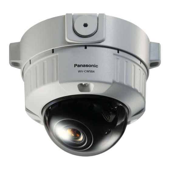
This illustration represents WV-CW504F.
Before attempting to connect or operate this product, please read these
instructions carefully and save this manual for future use.
The model number is abbreviated in some descriptions in this manual.
Advertisement
Table of Contents

Related Manuals for Panasonic WV-CW504S


Summary of Contents for Panasonic WV-CW504S
-
Page 1: Installation Guide
Installation Guide Color CCTV Camera WV-CW504F, WV-CW504FK Model No. WV-CW504S, WV-CW504SK This illustration represents WV-CW504F. Before attempting to connect or operate this product, please read these instructions carefully and save this manual for future use. The model number is abbreviated in some descriptions in this manual. - Page 2 WARNING: • This apparatus must be earthed. • Apparatus shall be connected to a mains socket outlet with a protective earthing con- nection. • The mains plug or an appliance coupler shall For Canada remain readily operable. This Class A digital apparatus complies with •...
-
Page 3: Important Safety Instructions
Important safety instructions 1) Read these instructions. 2) Keep these instructions. 3) Heed all warnings. 4) Follow all instructions. 5) Clean only with dry cloth. 6) Do not block any ventilation openings. Install in accordance with the manufacturer's instruc- tions. 7) Do not install near any heat sources such as radiators, heat registers, stoves, or other appara- tus (including amplifiers) that produce heat. -
Page 4: Limitation Of Liability
MENTS OF THIS PUBLICATION AND/OR THE CORRESPONDING PRODUCT (S). Disclaimer of warranty IN NO EVENT SHALL Panasonic Corporation BE LIABLE TO ANY PARTY OR ANY PERSON, EXCEPT FOR REPLACEMENT OR REASONABLE MAINTENANCE OF THE PRODUCT, FOR THE CASES, INCLUDING BUT NOT LIMITED TO BELOW:... -
Page 5: Table Of Contents
Contents Important safety instructions ......................3 Limitation of liability ........................4 Disclaimer of warranty ........................4 Preface ............................6 Features ............................6 About the user manuals ........................ 7 Trademarks and registered trademarks..................7 Precautions ........................... 8 Precautions for Installation ......................10 Major operating controls and their functions ................ -
Page 6: Preface
Preface This product is a 1/3-inch type {1/3"} CCD color CCTV camera. Connection of this product to a video monitor allows users to use this product as a monitoring camera. • WV-CW504F: This is a model with x2 varifocal lens. Mounting bracket and ceiling mount brack- et are optional. • WV-CW504S: This is a model with x2 varifocal lens. Mounting bracket is supplied, but ceiling mount bracket are optional. • WV-CW504FK: Lens, mounting bracket, and ceiling mount bracket are optional. -
Page 7: About The User Manuals
Intelligent VMD (i-VMD) functions of motion detection and object abandonment/removal detection equipped The motion and abandonment/removal of an object are detectable. The states of covering the camera with a cloth, a cap or others and changing the camera direction notably can be detected (Scene change detection). The detection resolution has been significantly improved as compared with a conventional type, and the introduction of the newly developed detection method has improved detection accuracy under the condition that the motion detection is prone to malfunction due to leaves swaying. -
Page 8: Precautions
Precautions The following points as well as the con- This product shall be installed in a vibra- tents of "Warning" and "Caution" shall be tion-free place. observed. Failure to observe this may cause screws and bolts to be loosened and consequently to fall Refer installation work to the dealer. - Page 9 [Precautions for use] Cleaning this product body Turn the power off when cleaning the product. This product has no power switch. Do not use strong abrasive detergent when Turn the power off when cleaning the product. cleaning this product. Otherwise, it may cause discoloration.
-
Page 10: Precautions For Installation
Precautions for Installation The following points as well as the contents of "Warning" and " Caution" shall be observed. Avoid moist or dusty places to install this Installation work shall be performed in accordance with the technology standard system. of the electric installation. Otherwise, lifetime of the internal parts may be shortened. - Page 11 Mounting screws • The screws and bolts must be tightened with an appropriate tightening torque according to the material and strength of the installation area. • Do not use an impact driver. Failure to observe this may cause overtightening and consequently damage to the screws.
-
Page 12: Major Operating Controls And Their Functions
Major operating controls and their functions w Video output cable q Power cord !9 Inner dome e Enclosure * This illustration shows the camera without the inner dome. r Panning table u Panning lock screw t Tilt adjusting table y Tilting lock screw i Focus lock knob o Zoom lock knob !0 Camera fixing screw... - Page 13 q Power cord !6 Setting button [(SET), ABF2/MENU] Confirms the setting contents. Refer to w Video output cable page 27 for further information about [ABF2]. e Enclosure !7 Heater output connector r Panning table The cable of heater unit (option) is con- Rotate this table to adjust the panning nected to this connector.
-
Page 14: Lens Mounting (Wv-Cw504Fk, Wv-Cw504Sk)
Lens Mounting (WV-CW504FK, WV-CW504SK) 1. Before mounting the lens, remove the protection sheet from the camera. 2. Mount the optional lens to the camera by turning the lens clockwise. Connector Connector 3. Insert the connector of lens into the connector of the camera. -
Page 15: Preparations
Preparations When installing the camera on a wall or a ceiling, there are two methods as specified below. (+ Next page) • Using a two-gang junction box • Using the mounting base WV-Q115 Refer to all work related to the installation of this product to qualified service personnel or system installer. -
Page 16: Using A Two-Gang Junction Box
Using a two-gang junction box • When the camera is installed using the two-gang junction box, mount the camera attachment (accessory) to the embedded box installed on the wall or ceiling as a first step. [Mounting position on wall or ceiling] 46 mm {1-13/16"} Two-gang junction box 83.5 mm {3-9/32"} Camera attachment (accessory) Note: •... - Page 17 Install the mounting base on the wall/ceiling. ø27 mm {1-1/16"} Cable access hole (A For use of the hole) 51 mm {2"} WV-Q115 Center of mounting base Female thread for conduit (For use of the hole A) (For use of the hole B) 85 mm {3-11/32"} 138 mm {5-7/16"} 138 mm...
- Page 18 Previously run the cables from the wall or ceiling through the cable access hole. Mount the attachment onto the mount bracket. Recommended tightening torque: 0.78 N·m {0.58 lbf·ft} Camera attachment Note: • For wall mounting: Installation shall be performed in such a manner that "MTOP" of the camera attachment faces upward.
-
Page 19: Camera Installation
Camera installation Mount the camera. <To mount the camera on a two-gang junction box> q Connect the power cord and the video output cable. (+ page 30) w Align the "OPEN" mark of the camera with the protrusion of the camera attachment. e Engage the attachment mounting screw of the camera with the camera mounting hole of the camera attachment and rotate the camera in the direction of the arrow to the "LOCK"... - Page 20 <To use the mounting base> q Attach the camera onto the camera attachment while aligning the "OPEN" mark of the camera with the projection of the camera attachment. Projection Important: • When mounting the camera body, cables shall be run between the camera attachment and mounting base as indicated by the arrow in the illustration.
- Page 21 w Engage the attachment mounting screw of the camera with the camera mounting hole of the camera attachment and rotate the camera in the direction of the arrow to the "LOCK" position to secure the camera to the camera attachment without any back- lash.
- Page 22 t Mount the supplied base cover on the mounting base. Important: • To prevent the cables from being caught when the base cover is attached, keep the cables inside the cable guide. Base cover y Use the bit for tamperproof screw (acces- sory) to tighten the fixing screws provided Base cover fixing screw on both sides of the base cover.
- Page 23 Remove the enclosure and inner dome from the main body by loos- ening the three fixing screws. Loosen the three fixing screws by using the provided bit for tamperproof screw. Detach the inner dome while pushing the parts with the "PUSH" indication. Press the parts with the "PUSH"...
-
Page 24: Adjust The Camera
Adjust the camera Be sure to view the monitor for adjustment when the camera angle is adjusted. Connect the monitor for adjustment (e.g. a small LCD) to the monitor output connector, and adjust the camera angle. When determining the camera angle, repeat fine follow the adjusting procedure of q, w, and e shown below. - Page 25 Adjusts the focus. Focus adjustment shall be performed when camera Focus lock knob angle adjustment are performed. Adjust the focus by following the adjusting proce- dure of q, w, and e shown below. q Loosen the zoom lock knob and move the knob NEAR NEAR Zoom lock knob...
- Page 26 To perform fine adjustment of the back focus after the ABF operation indicator goes off and automatic back focus is adjusted, use the right or left button. Note: • No operation for 10 seconds or more automatically clears the focus position indicator. • To change the angle of view by moving the zoom adjustment ring, also move the focus lock knob to adjust the focus.
- Page 27 Mount the enclosure and inner dome. Tighten the screws that have been loos- Cutout for Groove for mounting ened in Step 2 in page 23 using the sup- mounting plied driver bit. (Recommended tightening torque: 0.78 N·m {0.58 lbf·ft}) Important: • Attach the inner dome in accordance with the lens direction to not to change the lens direction.
-
Page 28: Waterproof Treatment For The Cable Joint Sections
Waterproof treatment for the cable joint sections Adequate waterproof treatment is required for the cables when the camera with exposed cables is installed by means of the mounting base WV-Q115 or it is installed under the eaves. The camera body is waterproof, but the cable ends are not waterproof. Be sure to use the supplied butyl tape at the connection parts of the power cord and video output cable to apply waterproof treatment in the following procedure. - Page 29 Important: • If open wiring is conducted, be sure to use conduits and run the cables inside the tubes to pro- tect the cables from direct sunlight. • When the conduit is connected at the lateral or bottom position, either of the arrow marks on the bracket shall be the top position. • When the conduit is connected from the top, the arrow mark on the attachment shall be either of the right or left position. <To connect conduit from the side or bottom> Arrow mark Connecting conduit <To connect conduit from the top> • For installation on the wall, do not connect the dehumidifying device at the upper side to pre- vent water from being stored in the dehumidifying device.
-
Page 30: Make A Connection
Make a connection Cautions: • ONLY CONNECT WV-CW504 TO 24 V AC OR 12 V DC CLASS 2 POWER SUPPLY. • Be sure to connect the grounding lead to the GND terminal. Brown (Live) To 24 V AC/12 V DC* power supply Blue (Neutral) Power cord Green/Yellow (GND) To GND (only for 24 V AC) (approx. 17 cm * When using 12 V DC power supply, {55.8 ft}) the optional heater unit is unavailable. - Page 31 • Cord length and wire gauge 24 V AC The recommended cord length and copper wire size are shown in the table for reference. The voltage supplied to the camera should be between 19.5 V AC and 28 V AC. Recommended wire gauge for 24 V AC line.
-
Page 32: How To Install The Heater Unit
Optional Heater Unit WV-CW5H (option) Installing the heater unit enables the camera to operate in a low-temperature environment below –30 °C {–22 °F}. The heater turns on automatically when the temperature inside the camera drops below +10 °C {50 °F} and turns off when the temperature rises. A small fan inside the unit will mini- mize condensation on the surface of the enclosure caused by changes in ambient temperature unless temperatures change too rapidly. -
Page 33: About The Setup Menus
About the setup menus Performing each setting item in the setup menu should be completed in advance to use this unit. Perform the settings for each item in accordance with the conditions of the camera shooting area. Refer to the operating instructions (PDF) for further information. Setup menu list Setup item Description... - Page 34 Setup item Description SPECIAL CHROMA GAIN Adjusts the chroma level. AP GAIN Adjusts the aperture level. PEDESTAL Adjusts the pedestal (brightness) level. Adjusts the chroma phase (hue) level. PIX OFF Corrects image defects such as flaws. CAMERA RESET Restores the settings in the setup menu to the default settings. SER.NO.
-
Page 35: Basic Operation
Basic operation The description below explains how to operate the setup menu basically. The operations in the setup menu are performed with the operation buttons (+ page 12) after call- ing up the setup menu on the connected video monitor. The operations in the setup menu can also be performed through the system controller (option). - Page 36 Screenshot 3 The selected setup screen in the setup menu appears on the screen. Step 4 **CAMERA SETUP** Perform the settings for each item. SCENE1 • Selection of setting item: SHUTTER Press the up or down button to move the ON(HIGH) SENS UP cursor.
-
Page 37: Screen Transition Diagram
SENS UP WHITE BAL ATW1 HIGH BW MODE AUTO1 i-VMD RET TOP END "SYSTEM SETUP" screen **SYSTEM SETUP** SYNC LENS PANASONIC PRIVACY ZONE STABILIZER EL-ZOOM UPSIDE-DOWN RET TOP END "BACK-FOCUS SETUP" screen **BACK-FOCUS SETUP** PUSH SW MANUAL-ADJ AUTO SETUP-SW LOCK OFF NEAR .. -
Page 38: Troubleshooting
Troubleshooting Before asking for repairs, check the symptoms with the following table. Contact your dealer if a problem cannot be solved even after checking and trying the solution in the table or a problem is not described below. Reference Symptom Cause/solution pages • A re the power cord and coaxial cable... -
Page 39: Specifications
Specifications • Basic Power source: 24 V AC 60 Hz, 12 V DC Power consumption: 24 V AC: 3.4 W (without heater unit) 14 W (with heater unit) 12 V DC: 280 mA* Ambient operating temperature: –10 °C to +50 °C {+14 °F to +122 °F} –30 °C to +50 °C {–22 °F to +122 °F}** Ambient operating humidity: Less than 90 % (no condensation) - Page 40 HIGH/LOW Color/BW: AUTO1/AUTO2/ON/OFF Intelligent VMD (i-VMD): Motion detection Object abandonment/removal detection Scene change detection Number of scene file: Lens: PANASONIC/OTHER Privacy zone: ON (1)/ON (2)/OFF Image stabilizer: ON/OFF Electronic zoom: ON (Up to 2x)/OFF Image flip: ON/OFF Auto back focus:...
-
Page 41: Standard Accessories
Standard accessories CD-ROM* ..............1 pc. Installation Guide (this book) ........1 pc. Warranty card ............. 1 pc. *The CD-ROM contains the operating instructions (PDF). The following parts are used during installation procedures. Base cover (for WV-CW504S, WV-CW504SK) ... 1 pc. Mounting base (for WV-CW504S, WV-CW504SK) ...... - Page 44 Panasonic System Networks Company of America, Unit of Panasonic Corporation of North America www.panasonic.com/business/ For customer support, call 1.800.528.6747 Three Panasonic Way, Secaucus, New Jersey 07094 U.S.A. Panasonic Canada Inc. 5770 Ambler Drive, Mississauga, Ontario, L4W 2T3 Canada (905)624-5010 www.panasonic.ca ©...
Need help?
Do you have a question about the WV-CW504S and is the answer not in the manual?
Questions and answers