Table of Contents
Advertisement
Quick Links
Installation Guide
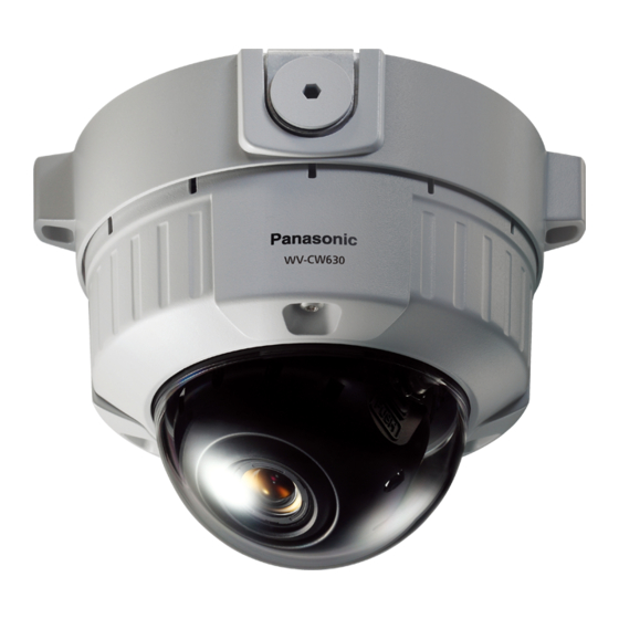
Color CCTV Camera
WV-CW630S/G
Model No.
WV-CW634SE
This illustration represents WV-CW630S/G.
For information about how to perform the settings and how to operate the
camera, refer to the Operating Instructions on the provided CD-ROM.
Before attempting to connect or operate this product, please read these
instructions carefully and save this manual for future use.
The model number is abbreviated in some descriptions in this manual.
Advertisement
Table of Contents

Related Manuals for Panasonic WV-CW634


Summary of Contents for Panasonic WV-CW634
- Page 1 Installation Guide Color CCTV Camera WV-CW630S/G Model No. WV-CW634SE This illustration represents WV-CW630S/G. For information about how to perform the settings and how to operate the camera, refer to the Operating Instructions on the provided CD-ROM. Before attempting to connect or operate this product, please read these instructions carefully and save this manual for future use.
- Page 2 WARNING: • This apparatus must be earthed. • Apparatus shall be connected to a mains socket outlet with a protective earthing con- nection. • The mains plug or an appliance coupler shall remain readily operable. • All work related to the installation of this prod- uct should be made by qualified service per- sonnel or system installers.
- Page 3 For Europe We declare under our sole responsibility that the product to which this declaration relates is in conformity with the standard or other normative document following the provisions of Directive 2004/108/EC. Wir erklären in alleiniger Verantwortung, daß das Produkt, auf das sich diese Erklärung bezieht, mit der folgenden Norm oder normativen Dokument übereinstimmt.
-
Page 4: Important Safety Instructions
Important safety instructions 1) Read these instructions. 2) Keep these instructions. 3) Heed all warnings. 4) Follow all instructions. 5) Do not block any ventilation openings. Install in accordance with the manufacturer's instruc- tions. 6) Do not install near any heat sources such as radiators, heat registers, stoves, or other appara- tus (including amplifiers) that produce heat. 7) Protect the power cord from being walked on or pinched particularly at plugs, convenience receptacles, and the point where they exit from the apparatus. -
Page 5: Limitation Of Liability
THIS PUBLICATION COULD INCLUDE TECHNICAL INACCURACIES OR TYPOGRAPHICAL ERRORS. CHANGES ARE ADDED TO THE INFORMATION HEREIN, AT ANY TIME, FOR THE IMPROVE- MENTS OF THIS PUBLICATION AND/OR THE CORRESPONDING PRODUCT (S). Disclaimer of warranty IN NO EVENT SHALL Panasonic System Networks Co., Ltd. BE LIABLE TO ANY PARTY OR ANY PERSON, EXCEPT FOR REPLACEMENT OR REASONABLE MAINTENANCE OF THE PRODUCT, FOR THE CASES, INCLUDING BUT NOT LIMITED TO BELOW: (1) ANY LOSS OR DAMAGE, INCLUDING WITHOUT LIMITATION, DIRECT OR INDIRECT, SPECIAL, CONSEQUENTIAL OR EXEMPLARY, ARISING OUT OF OR RELATING TO THE PRODUCT; (2) ANY INCONVENIENCE, LOSS, OR DAMAGE CAUSED BY INAPPROPRIATE USE OR NEGLIGENT OPERATION OF THE USER;... -
Page 6: Table Of Contents
Contents Important safety instructions ......................4 Limitation of liability ........................5 Disclaimer of warranty ........................5 Preface ............................7 Features ............................7 About the user manuals ........................ 8 Trademarks and registered trademarks..................8 Precautions ........................... 9 Precautions for Installation ......................11 Major operating controls and their functions ................ -
Page 7: Preface
Preface This product is a 1/3-inch type {1/3"} CCD color CCTV camera. Connection of this product to a video monitor allows users to use this product as a monitoring camera. Features Super Dynamic 6 For photographic subjects which contain high contrast between the bright and dark areas, light compensation on the pixel level will result in more natural-looking images. Introduction of newly developed high-resolution CCD The introduction of the newly developed CCD with 976 of horizontal pixels has led to the horizontal resolution of as high as 700 TV lines (typ.). -
Page 8: About The User Manuals
Note: • The VMD function is not the dedicated function to prevent thefts, fires, etc. We are not responsible for any accidents or damages caused by applying the function for the above purposes. Optional heater unit can be connected When using the optional heater unit, the product can be used at temperatures within –30 °C to +60 °C and humidity within 10 % to 90 %. The camera conforms to the IP66 and provides high dust resistance and waterproof performance. -
Page 9: Precautions
Precautions The following points as well as the con- This product shall be installed in a vibra- tents of "Warning" and "Caution" shall be tion-free place. observed. Failure to observe this may cause screws and bolts to be loosened and consequently to fall Refer installation work to the dealer. - Page 10 [Precautions for use] Cleaning this product body Turn the power off when cleaning the product. This product has no power switch. Do not use strong abrasive detergent when Turn the power off when cleaning the product. cleaning this product. Otherwise, it may cause discoloration. When using a chemical cloth for To keep on using with stable performance cleaning, read the caution provided with the Parts of this product may deteriorate and it chemical cloth product.
-
Page 11: Precautions For Installation
Precautions for Installation The following points as well as the contents of "Warning" and " C aution" shall be observed. Panasonic assumes no responsibility for • Locations where the temperature is not injuries or property damage resulting from within –10 °C to +60 °C. (When using the failures arising out of improper installa- optional heater unit, the product can be tion or operation inconsistent with this used at temperatures within –30 °C to... - Page 12 Mounting screws • The screws and bolts must be tightened with an appropriate tightening torque according to the material and strength of the installation area. • Do not use an impact driver. Failure to observe this may cause overtightening and consequently damage to the screws. • When a screw is tightened, make the screw at a right angle to the surface. After tightening the screws or bolts, perform visual check to ensure tightening is enough...
-
Page 13: Major Operating Controls And Their Functions
Major operating controls and their functions w Video output cable q Power cord !9 Inner dome e Enclosure @0 Dome * This illustration shows the camera without the inner dome. r Panning table u Panning lock screw t Tilt adjusting table y Tilting lock screw i Focus lock knob o Zoom lock knob... - Page 14 q Power cord !5 Down button [(DOWN), ABF1] Moves the cursor downward and selects items in the setup menu. Refer to page 30 w Video output cable for further information about [ABF1]. e Enclosure ( Pressing and holding for 3 s, image upside-down) r Panning table Rotate this table to adjust the panning !6 Setting button [(SET), ABF2/MENU] angle of the camera.
-
Page 15: Preparations
Preparations When installing the camera on a wall or a ceiling, there are two methods as specified below. (+ Next page) • Using a two-gang junction box (locally procured) • Using the camera mount bracket (accessory) Refer to all work related to the installation of this product to qualified service personnel or system installer. Important: • Prepare the mounting screw according to the material of the area where the attachment plate (accessory) is to be installed. In this case, wood screws and nails should not be used. For mounting a camera on a concrete ceiling, use an anchor bolt (M4) or an AY plug bolt (M4) for securing. - Page 16 Using a two-gang junction box (locally procured) • When the camera is installed using the two-gang junction box, mount the attachment plate (accessory) to the embedded box installed on the wall or ceiling as a first step. [Mounting position on wall or ceiling] 46 mm Two-gang junction box 83.5 mm Attachment plate (accessory) Note: • For wall mounting: Installation shall be performed in such a manner that "...
- Page 17 Install the camera mount bracket on the wall/ceiling. ø27 mm Cable access hole (A For use of the hole) 51mm Camera mount bracket Center of camera mount bracket Female thread for conduit Cap for the female thread for the conduit (For use of the hole A) (For use of the hole B) 85 mm...
- Page 18 Previously run the cables from the wall or ceiling through the cable access hole. Mount the attachment plate onto the mount bracket. Recommended tightening torque: 0.78 N·m Attachment plate Note: • For wall mounting: Installation shall be performed in such a manner that " TOP" of the attachment plate faces upward.
- Page 19 Important: • If open wiring is conducted, be sure to use conduits and run the cables inside the tubes to pro- tect the cables from direct sunlight. • When the conduit is connected at the lateral or bottom position, either of the arrow marks on the bracket shall be the top position. • When the conduit is connected from the top, the arrow mark on the attachment shall be either of the right or left position. <To connect conduit from the side or bottom> Arrow mark Connecting Connecting conduit <To connect conduit from the top> Female thread for conduit • Installation work shall be such that there is no intrusion of water into the architecture through the conduits having been joined.
-
Page 20: Make A Connection
Make a connection Cautions: • ONLY CONNECT WV-CW634 TO 24 V AC OR 12 V DC CLASS 2 POWER SUPPLY (UL 1310/CSA 223) or LIMITED POWER SOURCE (IEC/EN/UL/CSA 60950-1). • Be sure to connect the grounding lead to the GND terminal. Power cord To 24 V AC/12 V DC* (WV-CW634: approx. 17 cm) Brown (Live) power supply (WV-CW634) (WV-CW630: approx. - Page 21 • Shrinking the cable-entry seal is a onetime Important: procedure. Do not shrink the cable-entry When using 12 V DC power supply, the seal until it has been ascertained that unit heater is unavailable. is functioning. ONLY CONNECT THIS TO 24 V AC or 12 V DC CLASS 2 POWER SUPPLY. • Cord length and wire gauge 24 V AC The recommended cord length and copper wire size are shown in the table for reference.
- Page 22 Waterproof treatment for the cable joint sections Adequate waterproof treatment is required for the cables when the camera with exposed cables is installed by means of the camera mount bracket or it is installed under the eaves. The camera body is waterproof, but the cable ends are not waterproof. Be sure to use the supplied waterproof tape at the connection parts of the power cord and video output cable to apply waterproof treatment in the following procedure. Failure to observe this may cause water leakage resulting in malfunction. When using power cord When using video output cable <How to wind the supplied waterproof tape> Stretch the tape by approx. twice (see the illustration below) and wind it around the cable. Insuf- ficient tape stretch causes insufficient waterproofing. Stretch the tape to about twice. Double length Note: • To install this product outdoors, be sure to waterproof the cables. The camera body is water- proof (IEC IP66 or equivalent) only when installation specified in this document and appropriate waterproofing are properly performed. The bracket is not waterproof.
- Page 23 Installing the heater unit enables the camera to operate in a low-temperature environment below –30 °C. The heater turns on automatically when the temperature inside the camera drops below +10 °C and turns off when the temperature rises. A small fan inside the unit will minimize conden- sation on the surface of the enclosure caused by changes in ambient temperature unless tempera- tures change too rapidly. Important: • When using 12 V DC power supply, the optional heater unit is unavailable (WV-CW634). • Turning the heater on and off may disturb the camera images. • The power supply of the camera shall be turned off when mounting or dismounting the heater. When servicing, pay attention to high temperature on the surface of the heater unit. Disconnect the harness and wait until the heater unit cools. • When the camera is installed and operated in low temperatures below –10 °C, normal images may not be obtained immediately after startup. In such a case, wait approxilately 60 minutes or...
-
Page 24: Camera Installation
Camera installation Mount the camera. <To mount the camera on a two-gang junction box> q Connect the power cord and the video output cable. (+ page 20) w Align the "OPEN" mark of the camera with the protrusion of the attachment plate. e Engage the attachment mounting screw of the camera with the camera mounting hole of the attachment plate and rotate the camera in the direction of the arrow to the "LOCK" position to secure the camera to the attachment plate without any backlash. Protrusion Camera mounting hole Attachment mounting screw... - Page 25 <To use the camera mount bracket> q Attach the camera onto the attachment plate while aligning the "OPEN" mark of the camera with the projection of the attachment plate. Projection Important: • When mounting the camera body, cables shall be run between the attachment plate and cam- era mount bracket as indicated by the arrow in the illustration. * Cable running as indicated by the arrow is an example. Cable running shall be varied with installation environment.
- Page 26 w Engage the attachment mounting screw of the camera with the camera mounting hole of the attachment plate and rotate the camera in the direction of the arrow to the "LOCK" position to secure the camera to the attachment plate without any backlash. Projection e Connect the power cord and the video output cable at the side of the camera mount bracket. (+ page 20) Apply waterproof treatment to the con- nected section. (+ page 22)
- Page 27 t Mount the supplied base cover on the camera mount bracket. Important: • To prevent the cables from being caught when the base cover is attached, keep the cables inside the cable guide. Base cover y Use the bit for tamperproof screw (acces- sory) to tighten the fixing screws provided Base cover fixing screw on both sides of the base cover. (Recommended tightening torque: 0.78 N·m)
- Page 28 Remove the enclosure and inner dome from the main body by loos- ening the three fixing screws. Loosen the three fixing screws by using the provided bit for tamperproof screw. Detach the inner dome while pushing the parts with the "PUSH" indication. Press the parts with the "PUSH" indication. Important: • Do not hold the inner dome when carrying the camera. Otherwise, the camera part...
- Page 29 Adjust the camera Be sure to view the monitor for adjustment when the camera angle is adjusted. Connect the monitor for adjustment (e.g. a small LCD) to the monitor output connector, and adjust the camera angle. When determining the camera angle, repeat fine follow the adjusting procedure of q, w, and e shown below. Tilt adjusting table Tilting lock screw Monitor output connector (RCA) Panning table...
- Page 30 Adjusts the focus. Focus adjustment shall be performed when camera Focus lock knob angle adjustment are performed. Adjust the focus by following the adjusting proce- dure of q, w, and e shown below. q Loosen the zoom lock knob and move the NEAR NEAR Zoom lock knob knob between TELE and WIDE to obtain the WIDE WIDE TELE TELE...
- Page 31 To perform fine adjustment of the back focus after the ABF operation indicator goes off and automatic back focus is adjusted, use the right or left button. Note: • No operation for 10 seconds or more automatically clears the focus position indicator. • To change the angle of view by moving the zoom adjustment ring, also move the focus lock knob to adjust the focus.
- Page 32 Mount the enclosure and inner dome. Tighten the screws that have been loos- Cutout for Groove for ened in Step 2 in page 28 using the supplied mounting mounting driver bit. (Recommended tightening torque: 0.78 N·m) Important: • Attach the inner dome in accordance with the lens direction to not to change the lens direction. • Check if the tabs of the inner dome are firmly fit. • Remove the cushioning (pink sheet) from the inside of the dome and the protection sheet from the outside of the dome.
-
Page 33: Setup Menu
Setup menu Performing each setting item in the setup menu should be completed in advance to use this unit. Perform the settings for each item in accordance with the installation conditions and customer requirements. List of setup menu Setup item Description CAMERA ID This item specifies the camera title. The camera title that indicates the camera location and other information about the camera is created with alphanumeric characters and symbol, and then displayed on the screen. CAMERA Performs the camera operation settings. SCENE 1/ Selects a scene file. It is possible to register and save the settings as a SCENE 2 scene file in case that it is necessary to change the settings such when shooting at night. Selects the method of controlling the quantity of light in accordance with the ALC/ELC lens to be used. SHUTTER Specifies the electronic shutter speed. Specifies gain adjustment. SENS UP Specifies electronic sensitivity enhancement. -
Page 34: Basic Operation
Basic operation The operations in the setup menu are performed with the operation buttons after calling up the setup menu on the connected video monitor. The description below explains how to operate the setup menu basically. Screenshots of WV-CW630S/G are shown as an example. Screenshot 1 Hold down the [SET] button for about 2 Step 1 seconds to call up the top screen of the setup Press the [UP] or [DOWN] button to move the menu. cursor to "END". MODEL WV-CW630 SERIES CAMERA ID CAMERA Step 2 SYSTEM... - Page 35 Screenshot 3 The selected setup screen in the setup menu Step 4 appears on the screen. Perform the settings for each item. **CAMERA SETUP** • Selection of setting item: SCENE1 ALC/ELC Press the [UP] or [DOWN] button to move SHUTTER the cursor. ON(HIGH) SENS UP WHITE BAL ATW1 • Change of settings: HIGH Press the [RIGHT] or [LEFT] button.
- Page 36 Screen transition diagram Top screen "CAMERA ID" screen MODEL WV-CW630 SERIES **CAMERA ID** CAMERA ID 0123456789 CAMERA ABCDEFGHIJKLM SYSTEM NOPQRSTUVWXYZ BACK-FOCUS ().,'":;&#!?= SPECIAL +- */%$ LANGUAGE SPACE POSI RET TOP END RESET "CAMERA SETUP" screen ....SETUP DISABLE **CAMERA SETUP** SCENE1 ALC/ELC SHUTTER...
-
Page 37: Troubleshooting
Troubleshooting Before asking for repairs, check the symptoms with the following table. Contact your dealer if a problem cannot be solved even after checking and trying the solution in the table or a problem is not described below. Reference Symptom Cause/solution pages • A re the power cord and coaxial cable connected appropriately? → C heck whether the connection is appropriately established. • I s the adjusting monitor connected? → C heck whether connection is estab- lished. • I s the monitor brightness appropriately No image displayed adjusted, or is the contrast appropriately adjusted? – → C heck whether the monitor settings are appropriate. • W ere the shock absorbers in the dome cover already removed? – → C onfirm whether the shock absorbers have been already removed. -
Page 38: Specifications
Specifications • Basic WV-CW630 WV-CW634 Power source 220 V AC to 240 V AC 50 Hz 24 V AC 50 Hz, 12 V DC 24 V AC: 3 .0 W (without heater unit) 4.6 W (without heater unit) Power consumption 13.2 W (with heater unit) 15.3 W (with heater unit) 12 V DC: 237 mA* Ambient operating temperature –10 °C to +60 °C / (with heater unit): –30 °C to +60 °C* Ambient operating humidity 10 % to 90 % (no condensation) Waterproof* Main body: IEC60529 (IP66) Shock resistance 50J, IEC60068-2-75 Video output VBS: 1.0 V [p-p]/75 Ω, PAL, BNC connector Dimensions ø164 mm × 146 mm (H), 191.5 mm (W) (Base Cover) Approx. 1.45 kg Approx. 1.35 kg Mass Attachment plate: 100 g Mount bracket: 350 g Main body: Aluminum die cast, light gray Finish Dome cover: Clear polycarbonate resin... - Page 39 Signal-to-noise ratio 52 dB (AGC Off) Dynamic range 54 dB typ. (Super Dynamic 6 ON) Monitor output VBS: 1.0 V [p-p]/75 Ω, PAL, RCA jack Camera title Up to 16 characters (alphanumeric characters, marks) Light control mode setting ALC/ALC+/ELC Super Dynamic 6 ON/ OFF High light compensation (HLC) ON (1)/ ON (2)/ OFF Fog compensation ON/OFF OFF (1/50 s), 1/120 s, 1/250 s, 1/500 s, 1/1000 s, 1/2000 s, Electronic shutter speed 1/4000 s, 1/10000 s, 1/120000 s ON (HIGH, MID, LOW)/OFF OFF/ AUTO (×2, ×4, ×6, ×10, ×16, ×32)/ FIX (×2, ×4, ×6, ×10, ×16, Sensitivity up ×32, ×64, ×128, ×256, ×512) White balance ATW1/ ATW2/ AWC (area can be set) Digital noise reduction HIGH/LOW Color/BW AUTO1/ AUTO2/ ON/ OFF Motion detection Scene change detection Number of scene file Privacy zone ON (1)/ ON (2)/ OFF Image stabilizer ON/OFF Electronic zoom ON (Up to 2x)/OFF Image flip ON/OFF Lens distortion correction 0 to 255 Auto back focus...
-
Page 40: Standard Accessories
Standard accessories CD-ROM* ..............1 pc. Installation Guide (this book) ........1 pc. *The CD-ROM contains the operating instructions (PDF). The following parts are used during installation procedures. Base cover ..............1 pc. Camera mount bracket ..........1 pc. Fixing screw for camera mount bracket ...... 5 pcs. (incl. 1 spare screw) Attachment plate ............1 pc. Bit for tamperproof screw ........... 1 pc. Waterproof tape ............1 pc. Optional Accessories Dome cover: WV-CW4SA (Smoke type) Heater unit: WV-CW5HA Ceiling mount bracket: WV-Q169A* (Use when installing camera on weak ceiling boards, etc.) Ceiling mount bracket: WV-Q105A* (Use when installing camera on weak ceiling boards, etc.) Ceiling hanging mount bracket: WV-Q121B (Use with the WV-Q124 (suspension mount bracket) to be able to install on a ceiling.) Wall mount bracket: WV-Q122A (Use with the WV-Q124 (suspension mount bracket) to be able to install on a wall.) Mount bracket: WV-Q124 (Use when installing camera using the... - Page 41 Disposal of Old Equipment Only for European Union and countries with recycling systems This symbol on the products, packaging, and/or accompanying documents means that used electrical and electronic products must not be mixed with general household waste. For proper treatment, recovery and recycling of old products, please take them to applicable collection points in accordance with your national legislation.
- Page 44 Panasonic Corporation http://www.panasonic.com Panasonic System Networks Co., Ltd. Fukuoka, Japan Authorised Representative in EU: Panasonic Testing Centre Panasonic Marketing Europe GmbH Winsbergring 15, 22525 Hamburg, Germany © Panasonic System Networks Co., Ltd. 2015 sL1115-2125 PGQX1941XA Printed in China...
Need help?
Do you have a question about the WV-CW634 and is the answer not in the manual?
Questions and answers