Table of Contents
Advertisement
Advertisement
Table of Contents

Subscribe to Our Youtube Channel
Related Manuals for Asus M4A87TD EVO


Summary of Contents for Asus M4A87TD EVO
- Page 1 M4A87TD...
- Page 2 Product warranty or service will not be extended if: (1) the product is repaired, modified or altered, unless such repair, modification of alteration is authorized in writing by ASUS; or (2) the serial number of the product is defaced or missing.
-
Page 3: Table Of Contents
Contents Notices ......................vi Safety information ..................vii About this guide ..................vii M4A87TD EVO specifications summary ........... ix Chapter 1 Welcome! ..................1-1 Package contents ................. 1-1 Special features ................1-1 1.3.1 Product highlights ............1-1 1.3.2 ASUS Unique Features ........... 1-2 Before you proceed .............. - Page 4 Knowing BIOS ................2-1 Updating BIOS ................2-1 2.2.1 ASUS Update utility ............2-2 2.2.2 ASUS EZ Flash 2 utility ........... 2-3 2.2.3 ASUS CrashFree BIOS 3 utility ........2-4 BIOS setup program ..............2-5 2.3.1 BIOS menu screen ............2-6 2.3.2...
- Page 5 Boot Device Priority ............2-23 2.8.2 Boot Settings Configuration .......... 2-23 2.8.3 Security ................. 2-24 Tools menu ................. 2-25 2.9.1 ASUS EZ Flash 2 ............2-25 2.9.2 Express Gate ............... 2-25 2.9.3 ASUS O.C. Profile ............2-26 2.9.4 AI NET 2................ 2-26 2.10...
-
Page 6: Notices
Complying with the REACH (Registration, Evaluation, Authorisation, and Restriction of Chemicals) regulatory framework, we published the chemical substances in our products at ASUS REACH website at http://green.asus.com/english/REACH.htm. DO NOT throw the motherboard in municipal waste. This product has been designed to enable proper reuse of parts and recycling. -
Page 7: Safety Information
Safety information Electrical safety • To prevent electrical shock hazard, disconnect the power cable from the electrical outlet before relocating the system. • When adding or removing devices to or from the system, ensure that the power cables for the devices are unplugged before the signal cables are connected. If possible, disconnect all power cables from the existing system before you add a device. -
Page 8: Conventions Used In This Guide
Where to find more information Refer to the following sources for additional information and for product and software updates. ASUS websites The ASUS website provides updated information on ASUS hardware and software products. Refer to the ASUS contact information. Optional documentation Your product package may include optional documentation, such as warranty flyers, that may have been added by your dealer. -
Page 9: M4A87Td Evo Specifications Summary
** Due to CPU spec., AMD 100 and 200 series CPUs support up to DDR3 1066MHz. With ASUS design, this motherboard can support up to DDR3 1333MHz. *** Refer to www.asus.com or this user manual for the Memory QVL (Qualified Vendors Lists) Multi-GPU support Supports ATI Quad-GPU CrossFireX™... - Page 10 Memory tuning from 1066MHz up to 2000MHz PCI Express frequency tuning from 100MHz up to 150MHz at 1MHz increment Overclocking protection: - ASUS C.P.R. (CPU Parameter Recall) Rear panel I/O ports 1 x PS/2 keyboard port (purple) 1 x PS/2 mouse port (green) 2 X USB 3.0/2.0 ports (blue)
- Page 11 BIOS features 8 Mb Flash ROM, SPI, AMI BIOS, PnP, DMI 2.0, WfM2.0, SM BIOS 2.5, ACPI 2.0a, Multi-language BIOS, ASUS EZ Flash 2, ASUS CrashFree BIOS 3 Manageability WfM 2.0, DMI 2.0, WOL by PME, WOR by PME, PXE...
-
Page 13: Welcome
® The motherboard delivers a host of new features and latest technologies, making it another standout in the long line of ASUS quality motherboards! Before you start installing the motherboard, and hardware devices on it, check the items in your package with the list below. -
Page 14: Asus Unique Features
This series’ high quality power components effective lowers system temperature to ensure longer component lifespan. ASUS M4A87TD EVO also features an extra 1-phase power for integrated memory/HT controller to provide independent power to vital components. ASUS M4A87TD EVO... -
Page 15: Asus Express Gate
PC components in real-time–helping save power and money! ASUS Hybrid OS ASUS Express Gate Express Gate is an ASUS exclusive OS that provides you with quick access to the Internet and key applications before entering the Windows ® ASUS Quiet Thermal Solutions... -
Page 16: Before You Proceed
Place six (6) screws into the holes indicated by circles to secure the motherboard to the chassis. Do not overtighten the screws! Doing so can damage the motherboard. Place this side towards the rear of the chassis. ASUS M4A87TD EVO... -
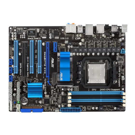
Page 17: Motherboard Layout
1.5.3 Motherboard layout 1.5.4 Layout contents Connectors/Jumpers/Slots Page ATX power connectors (24-pin EATXPWR, 4-pin ATX12V) 1-26 CPU socket AM3 CPU, Chassis and Power Fan connectors (4-pin CPU_FAN, 4-pin CHA_FAN1, 1-28 3-pin PWR_FAN) DDR3 DIMM slots MemOK! switch 1-19 Core Unlocker switch (CORE_UNLOCKER) 1-20 IDE connector (40-1 pin PRI_IDE) 1-25... -
Page 18: Central Processing Unit (Cpu)
Carefully insert the CPU into the socket until it fits in place. The CPU fits only in one correct orientation. DO NOT force the CPU into the socket to prevent bending the pins and damaging the CPU! Small triangle Gold triangle ASUS M4A87TD EVO... -
Page 19: Installing The Heatsink And Fan
When the CPU is in place, push down the socket lever to secure the CPU. The lever clicks on the side tab to indicate that it is locked. Install a CPU heatsink and fan following the instructions that came with the heatsink package. You can also refer to section 1.6.2 Installing the heatsink and fan for instructions. - Page 20 When the fan and heatsink assembly is in place, connect the CPU fan cable to the connector on the motherboard labeled CPU_FAN. Do not forget to connect the CPU fan connector! Hardware monitoring errors can occur if you fail to plug this connector. ASUS M4A87TD EVO...
-
Page 21: System Memory
• Due to CPU spec., AMD 100 and 200 series CPUs support up to DDR3 1066MHz. With ASUS Design, this motherboard can support up to DDR3 1333MHz. • When overclocking, some AMD CPU models may not support DDR3 1600 or higher frequency DIMMs. - Page 22 M4A87TD EVO Motherboard Qualified Vendors Lists (QVL) DDR3-2000MHz capability DIMM socket support (Optional) Chip Chip Vendor Part No. Size Timing Voltage Brand 1 DIMM 2 DIMM 4 DIMM 7-8-7- CORSAIR TW3X4G2000C7GT ES ver2.1 4GB(2 x 2GB) 2.1V • DDR3-1866MHz capability...
- Page 23 DDR3-1600MHz capability (continued) DIMM socket support (Optional) Chip Chip Vendor Part No. Size Timing Voltage Brand 1 DIMM 2 DIMM 4 DIMM CORSAIR TR3X3G1600C9Ver1.1(XMP) 3GB(3 x 1GB) 9-9-9-24 1.65 • • CORSAIR CMG4GX3M2A1600C6 4GB( 2x 2GB ) 6-6-6-18 1.65 • CORSAIR CMD4GX3M2A1600C8(XMP) 4GB(2 x 2GB)
- Page 24 • • (3 x 2GB) CORSAIR CMX8GX3M4A1333C9 9-9-9-24 • • • (4 x 2GB) Crucial CT12864BA1339.8FF MICRON D9KPT • • • MT8JF12864AY- Crucial CT12864BA1339.8SFD MICRON • • • 1G4D1 Crucial CT12872BA1339.9FF MICRON D9KPT(ECC) • • • 1-12 ASUS M4A87TD EVO...
- Page 25 DDR3-1333MHz capability (continued) DIMM socket support Chip (Optional) Vendor Part No. Size Chip NO. Timing Voltage Brand 1 DIMM 2 DIMM 4 DIMM Crucial BL25664BN1337.16FF(XMP) 7-7-7-24 1.65 • • • Crucial CT25664BA1339.16FF MICRON D9KPT • • • Crucial CT25664BA1339.16SFD MICRON D9JNM •...
- Page 26 Patriot PVT36G1333ELK 9-9-9-24 1.65 • • (3 x 2GB) Silicon NT5CB128M8AN- SP001GBLTU1333S01 NANYA • • Power Silicon SP001GBLTU133S02 S-POWER I0YT3E0 • Power Silicon SP002GBLTU133S02 S-POWER I0YT3E0 • • • Power UMAX E41302GP0-73BDB UMAX U2S24D30TP-13 • • 1-14 ASUS M4A87TD EVO...
- Page 27 Dual-channel memory configuration. • C*: Supports four modules inserted into both the blue slots and the black slots as two pairs of Dual-channel memory configuration. Visit the ASUS website for the latest QVL. Chapter 1: Product introduction 1-15...
-
Page 28: Installing A Dimm
DIMM. Remove the DIMM from the socket. Support the DIMM lightly with your fingers when pressing the retaining clips. The DIMM might get damaged when it flips out with extra force. 1-16 ASUS M4A87TD EVO... -
Page 29: Expansion Slots
Expansion slots In the future, you may need to install expansion cards. The following sub-sections describe the slots and the expansion cards that they support. Unplug the power cord before adding or removing expansion cards. Failure to do so may cause you physical injury and damage motherboard components. -
Page 30: Jumper
• Due to the chipset behavior, AC power off is required to enable C.P.R. function. You must turn off and on the power supply or unplug and plug the power cord before rebooting the system. 1-18 ASUS M4A87TD EVO... -
Page 31: Onboard Switches
If the installed DIMMs still fail to boot after the whole tuning process, the DRAM_LED lights continuously. Replace the DIMMs with ones recommended in the Memory QVL (Qualified Vendors Lists) in this user manual or on the ASUS website at www.asus.com. - Page 32 • The system will use the last setting you have made. • If you clear the CMOS or load the BIOS setup defaults, the ASUS Core Unlocker item in the BIOS menu follows the current setting of the Core Unlocker switch.
-
Page 33: Onboard Leds
Core Unlocker LED The Core Unlocker LED lights when the Core Unclocker switch is turned to Enable. The Core Unlocker LED keeps on lighting even though the ASUS Core Unlocker item in the BIOS menu is set to [Disabled]. Chapter 1: Product introduction... - Page 34 DRAM LED checks DRAM status during motherboard booting process. If an error is found , the LED will continue lighting until the problem is solved. This user-friendly design provides an intuitional way to locate the root problem within a second. 1-22 ASUS M4A87TD EVO...
-
Page 35: Connectors
1.12 Connectors 1.12.1 Rear panel connectors PS/2 mouse port (green). This port is for a PS/2 mouse. USB 2.0 ports 3 and 4. These 4-pin Universal Serial Bus (USB) ports are available for connecting USB 2.0 devices. LAN (RJ-45) port. This port allows Gigabit connection to a Local Area Network (LAN) through a network hub. - Page 36 Front Speaker Out Front Speaker Out Pink Mic In Mic In Mic In Mic In Orange – – Center/Subwoofer Center/Subwoofer Black – Rear Speaker Out Rear Speaker Ou Rear Speaker Out Gray – – – Side Speaker Out 1-24 ASUS M4A87TD EVO...
-
Page 37: Internal Connectors
1.12.2 Internal connectors IDE connector (40-1 pin PRI_IDE) The onboard IDE connector is for Ultra DMA 133/100/66 signal cable. There are three connectors on each Ultra DMA 133 / 100 / 66 signal cable: blue, black, and gray. Connect the blue connector to the motherboard’s IDE connector, then select one of the following modes to configure your devices: Drive jumper setting Mode of device(s) - Page 38 The system may become unstable or may not boot up if the power is inadequate. • If you are uncertain about the minimum power supply requirement for your system, refer to the Recommended Power Supply Wattage Calculator at http://support.asus. com/PowerSupplyCalculator/PSCalculator.aspx?SLanguage=en-us for details. 1-26...
- Page 39 SB850 Serial ATA Serial ATA 6.0 Gb/s connectors (7-pin SATA 1-6) ® These connectors are for the Serial ATA 6.0 Gb/s signal cables for Serial ATA hard disk drives and optical disc drives. If you installed Serial ATA hard disk drives, you can create a RAID 0, RAID 1, RAID 5, or RAID 10 configuration through the onboard AMD SB850 controller.
- Page 40 • The CPU_FAN connector supports the CPU fan of maximum 2A (24 W) fan power. • Only the CPU_FAN and CHA_FAN1 connectors support the ASUS Fan Xpert feature. • If you install two VGA cards, we recommend that you plug the rear chassis fan cable to the motherboard connector labeled CHA_FAN1 for better thermal environment.
-
Page 41: System Panel Connector (20-8 Pin Panel)
System panel connector (20-8 pin PANEL) This connector supports several chassis-mounted functions. • System power LED (2-pin PLED) This 2-pin connector is for the system power LED. Connect the chassis power LED cable to this connector. The system power LED lights up when you turn on the system power, and blinks when the system is in sleep mode. - Page 42 Never connect a 1394 cable to the USB connectors. Doing so will damage the motherboard! The USB 2.0 module is purchased separately. Digital audio connector (4-1 pin SPDIF_OUT) This connector is for an additional Sony/Philips Digital Interface (S/PDIF) ports. The S/PDIF module is purchased separately. 1-30 ASUS M4A87TD EVO...
- Page 43 Front panel audio connector (10-1 pin AAFP) This connector is for a chassis-mounted front panel audio I/O module that supports either High Definition Audio or AC`97 audio standard. Connect one end of the front panel audio I/O module cable to this connector. •...
- Page 44 Never connect a USB cable to the IEEE 1394a connector. Doing so will damage the motherboard! The IEEE 1394a module is purchased separately. 1-32 ASUS M4A87TD EVO...
-
Page 45: Software Support
ASUS website at www.asus.com for updates. • For detailed software instructions, see the Manual folder in the Support DVD or download the latest software manual from the ASUS website at www.asus.com. To run the Support DVD Place the Support DVD to the optical drive. The DVD automatically displays the Drivers menu if Autorun is enabled in your computer. - Page 46 1-34 ASUS M4A87TD EVO...
-
Page 47: Knowing Bios
Refer to the corresponding sections for details on these utilities. Save a copy of the original motherboard BIOS file to a USB flash drive in case you need to restore the BIOS in the future. Copy the original motherboard BIOS using the ASUS Update utility. -
Page 48: Asus Update Utility
2.2.1 ASUS Update utility The ASUS Update is a utility that allows you to manage, save, and update the motherboard BIOS in Windows environment. ® • ASUS Update requires an Internet connection either through a network or an Internet Service Provider (ISP). -
Page 49: Asus Ez Flash 2 Utility
When the correct BIOS file is found, EZ Flash 2 performs the BIOS update process and automatically reboots the system when done. • Only a USB flash disk with FAT 32/16 format and single partition can support the ASUS EZ Flash 2 utility. -
Page 50: Asus Crashfree Bios 3 Utility
The BIOS file in the motherboard support DVD may be older than the BIOS file published on the ASUS official website. If you want to use the newer BIOS file, download the file at support.asus.com and save it to a USB flash drive. -
Page 51: Bios Setup Program
• The BIOS setup screens shown in this section are for reference purposes only, and may not exactly match what you see on your screen. • Visit the ASUS website at www.asus.com to download the latest BIOS file for this motherboard. -
Page 52: Bios Menu Screen
• The BIOS setup screens shown in this chapter are for reference purposes only, and may not exactly match what you see on your screen. • Visit the ASUS website at www.asus.com to download the latest BIOS information. ASUS M4A87TD EVO... -
Page 53: Navigation Keys
2.3.3 Navigation keys At the bottom right corner of a menu screen are the navigation keys for that particular menu. Use the navigation keys to select items in the menu and change the settings. Some of the navigation keys differ from one screen to another. 2.3.4 Menu items The highlighted item on the menu bar displays the specific items for that menu. -
Page 54: Main Menu
LBA/Large Mode [Auto] [Auto] Select [Auto] to enable the LBA mode (Logical Block Addressing mode) if the device supports this mode, and if the device was not previously formatted with LBA mode disabled. [Disabled] Disables this function. ASUS M4A87TD EVO... -
Page 55: Storage Configuration
Block (Multi-Sector Transfer) M [Auto] [Auto] When set to [Auto], the data transfer from and to the device occurs in multiple sectors at a time if the device supports multi-sector transfer feature. [Disabled] When set to [Disabled], the data transfer from and to the device occurs one sector at a time. -
Page 56: System Information
SATA connectors 5/6 and set them to [IDE] mode. 2.4.3 System Information This menu gives you an overview of the general system specifications. The BIOS automatically detects the BIOS information, CPU specification, and system memory in this menu. 2-10 ASUS M4A87TD EVO... -
Page 57: Ai Tweaker Menu
Ai Tweaker menu The Ai Tweaker menu items allow you to configure overclocking-related items. Take caution when changing the settings of the Ai Tweaker menu items. Incorrect field values can cause the system to malfunction. The default values of the following items vary depending on the CPU and memory modules you install on the motherboard. -
Page 58: Cpu Ratio
Allows you to set the DDR3 operating frequency. The configuration options vary with the CPU Bus Frequency item settings. Selecting a very high DRAM frequency may cause the system to become unstable! If this happens, revert to the default setting. 2-12 ASUS M4A87TD EVO... -
Page 59: Cpu/Nb Frequency
2.5.6 CPU/NB Frequency [Auto] Allows you to select the CPU/NB frequency. Configuration options: [Auto] [1200MHz] [1400MHz] [1600MHz] [1800MHz] [2000MHz] 2.5.7 HT Link Speed [Auto] Allows you to select the HyperTransport link speed. Configuration options: [Auto] [200MHz] [400MHz] [600MHz] [800MHz] [1000MHz] [1200MHz] [1400MHz] [1600MHz] [1800MHz] [2000MHz] 2.5.8 DRAM Timing Configuration... -
Page 60: Dram Driving Configuration
This item appears only when you set the CPU & NB Voltage Mode item to [Offset] and allows you to set the CPU Offset voltage. The values range from 0.003125V to 0.700000V with a 0.003125V interval. 2-14 ASUS M4A87TD EVO... -
Page 61: Cpu Vdda Voltage
CPU/NB Offset Voltage [Auto] This item appears only when you set the CPU & NB Voltage Mode item to [Offset] and allows you to set the CPU/NB Offset voltage. The values range from 0.003125V to 0.700000V with a 0.003125V interval. CPU Voltage [Auto] This item appears only when you set the CPU &... -
Page 62: Advanced Menu
[Enabled] Enables the AMD Cool’n’Quiet function. [Disabled] Disables this function. ASUS Core Unlocker [Disabled] [Enabled] Enables the ASUS Core Unlocker to get the full computing power of the processor. [Disabled] Disables this function. C1E Support [Enabled] [Enabled] Enables the C1E support function. This item should be enabled in order to enable the Enhanced Halt Sate. -
Page 63: Chipset
2.6.2 Chipset The Chipset menu allows you to change the advanced chipset settings. Select an item then press <Enter> to display the submenu. DRAM Controller configuration Channel Interleaving [XOR of Address bit] Configuration options: [Disabled] [Address bits 6] [Address bits 12] [XOR of Address bits [20:16, 6]] [XOR of Address bits [20:16, 9]] MemClk Tristate C3/ATLVID [Disabled] Configuration options: [Disabled] [Enabled]... -
Page 64: Usb Configuration
The items in this menu allow you to change the USB-related features. Select an item and press <Enter> to display the configuration options. The USB Devices Enabled item shows the auto-detected values. If no USB device is detected, the item shows None. 2-18 ASUS M4A87TD EVO... -
Page 65: Pcipnp
USB Support [Enabled] [Enabled] Enables the USB Host Controllers. [Disabled] Disables the controllers. The following items appear only when you set USB Support to [Enabled]. Legacy USB Support [Auto] [Auto] Allows the system to detect the presence of USB devices at startup. If detected, the USB controller legacy mode is enabled. -
Page 66: Power Menu
Allows you to enable or disable the Advanced Configuration and Power Interface (ACPI) support in the Application-Specific Integrated Circuit (ASIC). When set to [Enabled], the ACPI APIC table pointer is included in the RSDT pointer list. Configuration options: [Disabled] [Enabled] 2-20 ASUS M4A87TD EVO... -
Page 67: Apm Configuration
2.7.5 APM Configuration EuP Ready [Disabled] [Disabled] Disables the Energy Using Products (EuP) Ready function. [Enabled] Allows BIOS to switch off some power at S5 state to get system ready for the EuP requirement. When set to [Enabled], power for WOL, WO_USB, audio and onboard LEDs will be switched off at S5 state. - Page 68 CPU fan speed. Configuration options: [Performance] [Optimal] [Silent] Chassis Q-Fan Function [Disabled] Allows you to enable or disable the chassis Q-Fan feature that smartly adjusts the fan speeds for more efficient system operation. Configuration options: [Disabled] [Enabled] 2-22 ASUS M4A87TD EVO...
-
Page 69: Boot Menu
This allows you to enable or disable the full screen logo display feature. Configuration options: [Disabled] [Enabled] Set this item to [Enabled] to use the ASUS MyLogo 2™ feature. AddOn ROM Display Mode [Force BIOS] Sets the display mode for option ROM. Configuration options: [Force BIOS] [Keep Current] Bootup Num-Lock [On] Allows you to select the power-on state for the NumLock. -
Page 70: Security
The message “Password Installed” appears after you set your password successfully. To change the user password, follow the same steps as in setting a user password. Clear User Password Select this item to clear the user password. 2-24 ASUS M4A87TD EVO... -
Page 71: Tools Menu
(C)Copyright 1985-2010, American Megatrends, Inc. 2.9.1 ASUS EZ Flash 2 Allows you to run ASUS EZ Flash 2. When you press <OK>, a confirmation message appears. Use the left/right arrow key to select between [Yes] or [No], then press <OK> to confirm your choice. -
Page 72: Asus O.c. Profile
BIOS version. • Only the “xxx.CMO” file can be loaded. 2.9.4 AI NET 2 Check Realtek LAN cable [Disabled] Enables or disables checking of the Realtek LAN cable during the Power-On Self-Test (POST). Configuration options: [Disabled] [Enabled] 2-26 ASUS M4A87TD EVO... -
Page 73: Exit Menu
2.10 Exit menu The Exit menu items allow you to load the optimal or failsafe default values for the BIOS items, and save or discard your changes to the BIOS items. BIOS SETUP UTILITY Main Ai Tweaker Advanced Power Boot Tools Exit Exit Options... - Page 74 2-28 ASUS M4A87TD EVO...
-
Page 75: Asus Contact Information
+1-812-282-3777 +1-510-608-4555 Web site usa.asus.com Technical Support Telephone +1-812-282-2787 Support fax +1-812-284-0883 Online support support.asus.com ASUS COMPUTER GmbH (Germany and Austria) Address Harkort Str. 21-23, D-40880 Ratingen, Germany +49-2102-959911 Web site www.asus.de Online contact www.asus.de/sales Technical Support Telephone (Component) +49-1805-010923*...
Need help?
Do you have a question about the M4A87TD EVO and is the answer not in the manual?
Questions and answers