Table of Contents
Advertisement
Advertisement
Table of Contents

Related Manuals for Asus M4A78LT-M


Summary of Contents for Asus M4A78LT-M
- Page 1 M4A78LT-M...
- Page 2 Product warranty or service will not be extended if: (1) the product is repaired, modified or altered, unless such repair, modification of alteration is authorized in writing by ASUS; or (2) the serial number of the product is defaced or missing.
-
Page 3: Table Of Contents
Contents Notices ......................vi Safety information ..................vii About this guide ..................vii M4A78LT-M specifications summary ............ix Chapter 1: Product introduction Welcome! ..................1-1 Package contents ................. 1-1 Special features ................1-1 1.3.1 Product highlights ............1-1 1.3.2 Innovative ASUS features ..........1-3 Before you proceed .............. - Page 4 Chapter 2: BIOS information Managing and updating your BIOS ..........2-1 2.1.1 ASUS Update utility ............2-1 2.1.2 ASUS EZ Flash 2 utility ........... 2-2 2.1.3 ASUS CrashFree BIOS utility ......... 2-3 BIOS setup program ..............2-4 2.2.1 BIOS menu screen ............2-5 2.2.2...
- Page 5 Boot Device Priority ............2-18 2.6.2 Boot Settings Configuration .......... 2-18 2.6.3 Security ................. 2-19 Tools menu ................. 2-21 2.7.1 ASUS EZ Flash 2 ............2-21 2.7.2 Express Gate ..............2-21 2.7.3 ASUS O.C. Profile ............2-22 2.7.4 AI NET 2................ 2-22...
-
Page 6: Notices
Complying with the REACH (Registration, Evaluation, Authorisation, and Restriction of Chemicals) regulatory framework, we published the chemical substances in our products at ASUS REACH website at http://green.asus.com/english/REACH.htm. DO NOT throw the motherboard in municipal waste. This product has been designed to enable proper reuse of parts and recycling. -
Page 7: Safety Information
Safety information Electrical safety • To prevent electric shock hazard, disconnect the power cable from the electric outlet before relocating the system. • When adding or removing devices to or from the system, ensure that the power cables for the devices are unplugged before the signal cables are connected. If possible, disconnect all power cables from the existing system before you add a device. -
Page 8: Conventions Used In This Guide
Refer to the following sources for additional information and for product and software updates. ASUS websites The ASUS website provides updated information on ASUS hardware and software products. Refer to the ASUS contact information. Optional documentation Your product package may include optional documentation, such as warranty flyers, that may have been added by your dealer. -
Page 9: M4A78Lt-M Specifications Summary
4 x 240-pin DIMM slots support maximum 16GB unbuffered ECC and non-ECC DDR3 1800(O.C.) / 1600 (O.C.) / 1333 / 1066MHz memory modules * Refer to www.asus.com for the latest Memory QVL (Qualified Vendors List). ** When you install a total memory of 4GB or more,... - Page 10 SFS (Stepless Frequency Selection) - FSB tuning from 200MHz to 550MHz at 1MHz increment - PCIe frequency tuning from 100MHz up to 150MHz at 1MHz increment ASUS C.P.R. (CPU Parameter Recall) Accessories 2 x Serial ATA cables 1 x Ultra DMA 133/100 cable...
-
Page 11: Chapter 1: Product Introduction
® The motherboard delivers a host of new features and latest technologies, making it another standout in the long line of ASUS quality motherboards! Before you start installing the motherboard, and hardware devices on it, check the items in your package with the list below. - Page 12 HyperTransport™ 3.0 support HyperTransport™ 3.0 technology provides 2.6 times more bandwidth than HT1.0 that radically improves system efficiency for a smoother and faster computing environment. Cool ‘n’ Quiet Technology ® This motherboard supports the AMD Cool ‘n’ Quiet technology which ®...
-
Page 13: Innovative Asus Features
BIOS file using the bundled support DVD or a USB flash disk that contains the BIOS file. ASUS EZ Flash 2 ASUS EZ Flash 2 allows you to update the BIOS from a USB flash disk before entering the OS. ASUS Q-Fan... - Page 14 ASUS EPU ASUS EPU is a unique power saving technology that detects the current system loadings and adjusts the power consumption in real time. ASUS AI NET2 ASUS AI NET2 remotely detects the cable connection immediately after you turn on the system and any faulty cable connections are reported back up to 100 meters at 1 meter accuracy.
-
Page 15: Before You Proceed
ON, in sleep mode, or in soft-off mode. This is a reminder that you should shut down the system and unplug the power cable before removing or plugging in any motherboard component. The illustration below shows the location of the onboard LED. SB_PWR M4A78LT-M Standby Power Powered Off M4A78LT-M Onboard LED ASUS M4A78LT-M... -
Page 16: Motherboard Overview
Place eight screws into the holes indicated by circles to secure the motherboard to the DO NOT overtighten the screws! Doing so can damage the motherboard. Place this side towards the rear of the chassis. M4A78LT-M Chapter 1: Product introduction... -
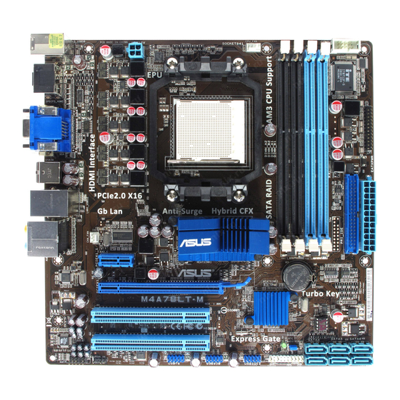
Page 17: Motherboard Layout
Serial port connectors (10-1 pin COM1) 1-29 USB connectors (10-1 pin USB78, USB910, 1-27 USB1112) LPT connector (26-1 pin LPT) 1-27 Digital audio connector (4-1 pin SPDIF_OUT) 1-22 IDE connector (40-1 pin PRI_IDE) 1-24 Front panel audio connector (10-1 pin AAFP) 1-28 ASUS M4A78LT-M... -
Page 18: Central Processing Unit (Cpu)
Installing the CPU To install a CPU: Locate the CPU socket on the motherboard. M4A78LT-M M4A78LT-M CPU socket AM3 Press the lever sideways to unlock the Socket lever socket, then lift it up to a 90°-100° angle. Ensure that the socket lever is lifted up to a 90°-100° angle; otherwise, the CPU will not fit in completely. - Page 19 Connect the CPU fan cable to the CPU_FAN connector on the motherboard. CPU_FAN M4A78LT-M M4A78LT-M CPU fan connector DO NOT forget to connect the CPU fan connector! Hardware monitoring errors can occur if you fail to plug this connector. ASUS M4A78LT-M...
-
Page 20: Installing The Heatsink And Fan
1.6.2 Installing the heatsink and fan Ensure that you use only AMD-certified heatsink and fan assembly. To install the CPU heatsink and fan: Place the heatsink on top of the installed CPU, ensuring that the heatsink fits properly on the retention module base. •... -
Page 21: System Memory
The motherboard comes with four Double Data Rate 3 (DDR3) Dual Inline Memory Modules (DIMM) sockets. The figure illustrates the location of the DDR3 DIMM sockets: Channel Sockets Channel A DIMM_A1 and DIMM_A2 Channel B DIMM_B1 and DIMM_B2 M4A78LT-M M4A78LT-M 240-pin DDR3 DIMM sockets ASUS M4A78LT-M 1-11... -
Page 22: Memory Configurations
OS if you want to install 4GB or more memory on the ® motherboard. • This motherboard does not support DIMMs made up of 256 megabits (Mb) chips or less. M4A78LT-M Motherboard Qualified Vendors Lists (QVL) DDR3-1866(O.C.)MHz capability DIMM support Chip Vendor Part No. - Page 23 • G.SKILL F3-10666CL9D-4GBPK 2048MB G.SKILL Heat-Sink Package • • • G.SkiLL F3-10666CL7T-6GBPK 6144MB(Kit of 3) Heat-Sink Package 7-7-7-18 • • • G.SKILL F3-1066CL9T-6GBNQ 6144MB(Kit of 3) Heat-Sink Package 9-9-9-24 • • • continued on the next page ASUS M4A78LT-M 1-13...
- Page 24 DDR3-1333MHz capability DIMM support Chip Vendor Part No. Size Chip NO. Brand GEIL DDR3-1333 CL9-9-9-24 1024MB Heat-Sink Package • • • GEIL GV34GB1333C7DC 2048MB Heat-Sink Package 7-7-7-24 • • • GEIL DDR3-1333 CL9-9-9-24 6144MB(Kit of 3) Heat-Sink Package • • •...
- Page 25 • C*: Supports two pairs of modules inserted into both the blue slots and the black slots as two pairs of dual-channel memory configuration. Visit the ASUS website at www.asus.com for the latest QVL. ASUS M4A78LT-M 1-15...
-
Page 26: Installing A Dimm
1.7.3 Installing a DIMM Unplug the power supply before adding or removing DIMMs or other system components. Failure to do so can cause severe damage to both the motherboard and the components. Press the retaining clips outward to DIMM notch unlock a DIMM socket. -
Page 27: Expansion Slots
This motherboard supports PCI Express x1 network cards, SCSI cards, and other cards that comply with the PCI Express specifications. 1.8.5 PCI Express x16 slot This motherboard supports a PCI Express x16 graphics card that comply with the PCI Express specifications. ASUS M4A78LT-M 1-17... -
Page 28: Jumpers
Normal Clear RTC (Default) M4A78LT-M Clear RTC RAM To erase the RTC RAM: 1. Turn OFF the computer and unplug the power cord. 2. Move the jumper cap from pins 1-2 (default) to pins 2-3. Keep the cap on pins 2-3 for about 5~10 seconds, then move the cap back to pins 1-2. -
Page 29: Connectors
Side Speaker Out port (gray). This port connects the side speaker in an 8-channel audio configuration. Refer to the audio configuration table on the next page for the function of the audio ports in 2, 4, 6, or 8-channel configuration. ASUS M4A78LT-M 1-19... - Page 30 Audio 2, 4, 6, or 8-channel configuration Port Headset 2-channel 4-channel 6-channel 8-channel Light Blue Line In Line in Line in Line in Lime Line Out Front Speaker Out Front Speaker Out Front Speaker Out Pink Mic In Mic In Mic in Mic in Orange...
- Page 31 • To play HD DVD or Blu-Ray Disc, ensure to use HDCP compliant devices and software. USB 2.0 ports 5 and 6. These two 4-pin Universal Serial Bus (USB) ports are available for connecting USB 2.0 devices. ASUS M4A78LT-M 1-21...
-
Page 32: Internal Connectors
This connector is for an additional Sony/Philips Digital Interface (S/PDIF) port. M4A78LT-M SPDIF_OUT M4A78LT-M Digital audio connector Ensure that the audio device of Sound playback is VIA High Definition Audio (the name may be different based on the OS). Go to Start > Control Panel > Sounds and Audio Devices >... -
Page 33: Atx Power Connectors
The system may become unstable or may not boot up if the power is inadequate. • If you are uncertain about the minimum power supply requirement for your system, refer to the Recommended Power Supply Wattage Calculator at http://support.asus. com/PowerSupplyCalculator/PSCalculator.aspx?SLanguage=en-us for details. ASUS M4A78LT-M... - Page 34 If any device jumper is set as “Cable-Select”, ensure that all other device jumpers have the same setting. PRI_IDE M4A78LT-M NOTE:Orient the red markings on the IDE ribbon cable to PIN 1. M4A78LT-M IDE connector 1-24 Chapter 1: Product introduction...
- Page 35 SATA1 SATA2 SATA3 M4A78LT-M M4A78LT-M SATA connectors • Install the Windows XP Service Pack 2 or later versions before using Serial ATA. ® • If you intend to create a SATA RAID set, set the type of the SATA connectors to [RAID] in the BIOS.
-
Page 36: System Panel Connector 20-8 Pin Panel
IDE_LED PWRSW RESET * Requires an ATX power supply M4A78LT-M System panel connector • System power LED (2-pin PLED) This 2-pin connector is for the system power LED. Connect the chassis power LED cable to this connector. The system power LED lights up when you turn on the system power, and blinks when the system is in sleep mode. -
Page 37: Usb Connectors
The LPT (Line Printing Terminal) connector supports devices such as a printer. LPT standardizes as IEEE 1284, which is the parallel port interface on IBM PC-compatible computers. SLCT BUSY ACK# SLIN# INIT# ERR# M4A78LT-M STB# PIN 1 M4A78LT-M Parallel Port Connector ASUS M4A78LT-M 1-27... - Page 38 Legacy AC’97 pin definition compliant definition M4A78LT-M Analog front panel connector • We recommend that you connect a high-definition front panel audio module to this connector to avail of the motherboard high-definition audio capability. • If you want to connect a high definition front panel audio module to this connector, set the Front Panel Select item in the BIOS to [HD Audio].
- Page 39 These are not jumpers! DO NOT place jumper caps on the fan connectors. Only the 4-pin CPU fan connector supports the ASUS Q-Fan feature. Serial port connectors (10-1 pin COM1) The connector is for a serial (COM) port. Connect the serial port module cable to the connector, then install the module to a slot opening at the back of the system chassis.
-
Page 40: Software Support
The contents of the Support DVD are subject to change at any time without notice. Visit the ASUS website at www.asus.com for updates. To run the Support DVD Place the Support DVD into the optical drive. -
Page 41: Chapter 2: Bios Information
BIOS in the future. Copy the original motherboard BIOS using the ASUS Update utility. 2.1.1 ASUS Update utility The ASUS Update is a utility that allows you to manage, save, and update the motherboard BIOS in Windows environment. ®... -
Page 42: Asus Ez Flash 2 Utility
Follow the onscreen instructions to complete the updating process. 2.1.2 ASUS EZ Flash 2 utility The ASUS EZ Flash 2 feature allows you to update the BIOS without using an OS-based utility. Before you start using this utility, download the latest BIOS file from the ASUS website at www.asus.com. -
Page 43: Asus Crashfree Bios Utility
2.1.3 ASUS CrashFree BIOS utility The ASUS CrashFree BIOS is an auto recovery tool that allows you to restore the BIOS file when it fails or gets corrupted during the updating process. You can restore a corrupted BIOS file using the motherboard support DVD or a removable device that contains the updated BIOS file. -
Page 44: Bios Setup Program
• The BIOS setup screens in this chapter are for reference only. They may not exactly match what you see on your screen. • Visit the ASUS website at www.asus.com to download the latest BIOS file for this motherboard. Chapter 2: BIOS information... -
Page 45: Bios Menu Screen
At the bottom right corner of a menu screen are the navigation keys for that particular menu. Use the navigation keys to select items in the menu and change the settings. Some of the navigation keys differ from one screen to another. ASUS M4A78LT-M... -
Page 46: Menu Items
2.2.4 Menu items The highlighted item on the menu bar displays the specific items for that menu. For example, selecting Main shows the Main menu items. The other items (Advanced, Power, Boot, Tools, and Exit) on the menu bar have their respective menu items. -
Page 47: Main Menu
CD-ROM drive. Select [ARMD] (ATAPI Removable Media Device) if your device is either a ZIP, LS-120, or MO drive. Configuration options: [Not Installed] [Auto] [CDROM] [ARMD] This item only appears in the Primary IDE Master/Slave and SATA 5/6 menus. ASUS M4A78LT-M... -
Page 48: Sata Configuration
LBA/Large Mode [Auto] Enables or disables the LBA mode. Setting this item to [Auto] enables the LBA mode if the device supports this mode, and if the device was not previously formatted with LBA mode disabled. Configuration options: [Disabled] [Auto] Block (Multi-Sector Transfer) M [Auto] Enables or disables data multi-sectors transfers. -
Page 49: System Information
The items and configuration options in this menu may vary depending on the AMD CPU type. CPU OverClocking [Auto] Selects the CPU overclocking options to achieve desired CPU internal frequency. Configuration options: [Manual] [Auto] [Overclock Profile] [Test Mode] ASUS M4A78LT-M... - Page 50 The following item only appears when you set CPU Overclocking to [Manual]. CPU/HT Reference Clock (MHz) [200] Sets the CPU/HT Reference Clock. Configuration options: [Min.=200] [Max.=550] The following item only appears when you set CPU Overclocking to [Overclock Profile]. Overclock Options [Auto] Selects the overclocking profile.
- Page 51 Chipset Over Voltage [Auto] Sets the chipset over voltage. The values range from 1.10000V to 1.59500V with a 0.01500V increment. Use the <+> / <-> keys to adjust the value. Configuration options: [Auto] [Max. = 1.59500V] [Min. = 1.10000V] ASUS M4A78LT-M 2-11...
-
Page 52: Cpu Configuration
2.4.2 CPU Configuration The items in this menu show the CPU-related information that the BIOS automatically detects. Microcode Updation [Enabled] Enables or disables Microcode Updation. Configuration options: [Disabled] [Enabled] Secure Virtual Machine Mode [Disabled] Enables or disables Secure Virtual Machine Mode (SVM). Configuration options: [Disabled] [Enabled] Cool ‘n’... -
Page 53: Ecc Configuration
• The [1GB] option only appears when you install 2GB system memory or more. Surround View [Auto] Disables or enables the Surround View function. Configuration options: [Auto] [Disabled] [Enabled] This item becomes user-configurable when you install an ATI graphics card into the PCIe x16 slot. ASUS M4A78LT-M 2-13... -
Page 54: Onboard Device Configuration
Frame Buffer Location [Above 4G] Configuration options: [Below 4G] [Above 4G] AMD 760 HDMI Audio [Enabled] Enables or disables the AMD 760 HDMI Audio. Configuration options: [Disabled] [Enabled] 2.4.4 Onboard Device Configuration Serial Port1 Address [3F8/IRQ4] Allows you to select the Serial Port1 base address. Configuration options: [Disabled] [3F8/IRQ4][2F8/IRQ3] [3E8/IRQ4] [2E8/IRQ3] Parallel Port Address [378] Allows you to select the Parallel Port base addresses. -
Page 55: Usb Configuration
Sets the maximum time that the BIOS waits for the USB storage device to initialize. Configuration options: [10 Sec] [20 Sec] [30 Sec] [40 Sec] Emulation Type [Auto] Allows you to set the emulation type. Configuration options: [Auto] [Floppy] [Forced FDD] [Hard Disk] [CDROM] ASUS M4A78LT-M 2-15... -
Page 56: Power Menu
Power menu The Power menu items allow you to change the settings for the Advanced Configuration and Power Interface (ACPI) and the Advanced Power Management (APM). Select an item then press <Enter> to display the configuration options. BIOS SETUP UTILITY Main Advanced Power... -
Page 57: Hw Monitor Configuration
The onboard hardware monitor automatically detects the voltage output through the onboard voltage regulators. Smart Q-Fan Function [Enabled] Enables or disables the ASUS Q-Fan feature that smartly adjusts the CPU fan speeds for more efficient system operation. Configuration options: [Disabled] [Enabled] Fan Auto Mode Start Voltage [5.0V] Sets the Smart Q-Fan start working voltage. -
Page 58: Boot Menu
Configuration options: [Removable Dev.] [Hard Drive] [ATAPI CD-ROM] [Disabled] • To select the boot device during system startup, press <F8> when ASUS logo appears. • To access Windows OS in Safe Mode, do any of the following: Press <F5>... -
Page 59: Security
<Enter> twice. The message Password uninstalled appears. If you forget your BIOS password, you can clear it by erasing the CMOS Real Time Clock (RTC) RAM. See section 1.9 Jumpers for information on how to erase the RTC RAM. ASUS M4A78LT-M 2-19... -
Page 60: Change User Password
After you have set a supervisor password, the other items appear to allow you to change other security settings. User Access Level [Full Access] This item allows you to select the access restriction to the Setup items. Configuration options: [No Access] [View Only] [Limited] [Full Access] No Access prevents user access to the Setup utility. -
Page 61: Tools Menu
2.7.1 ASUS EZ Flash 2 Allows you to run ASUS EZ Flash 2. When you press <Enter>, a confirmation message appears. Use the left/right arrow key to select between [Yes] or [No], then press <Enter> to confirm your choice. Please see section 2.1.2 for details. -
Page 62: Asus O.c. Profile
2.7.3 ASUS O.C. Profile This item allows you to store or load multiple BIOS settings. Add Your CMOS Profile Allows you to save the current BIOS file to the BIOS Flash. In the Name sub-item, type your profile name and press <Enter>, and then choose a profile number to save your CMOS settings in the Save to sub-item. -
Page 63: Exit Menu
When you select this option or if you press <F5>, a confirmation window appears. Select OK to load default values. Select Exit & Save Changes or make other changes before saving the values to the non-volatile RAM. ASUS M4A78LT-M 2-23... - Page 64 2-24 Chapter 2: BIOS information...
Need help?
Do you have a question about the M4A78LT-M and is the answer not in the manual?
Questions and answers
System will not access setup using delete key at startup. Just continues with boot cycle, but won't start using bootable disk. System shuts down after about 15 seconds.
If the Asus M4A78LT-M system does not access setup using the delete key at startup and shuts down after 15 seconds, follow these steps:
1. Replace hardware components one by one in this order to identify a defective device: memory module, CPU, motherboard, hard/optical disk drive, keyboard/mouse.
2. If a new hardware was recently added, remove it and reboot the system to check for compatibility or defects.
3. If BIOS settings were changed, reboot and enter BIOS to load the setup defaults.
If the defective component is found, contact the device retailer for service.
This answer is automatically generated