Table of Contents
Advertisement
Advertisement
Table of Contents

Related Manuals for Asus M4A78-EM 1394


Summary of Contents for Asus M4A78-EM 1394
- Page 1 M4A78-EM/1394...
- Page 2 Product warranty or service will not be extended if: (1) the product is repaired, modified or altered, unless such repair, modification of alteration is authorized in writing by ASUS; or (2) the serial number of the product is defaced or missing.
-
Page 3: Table Of Contents
Welcome! ..................1-1 Package contents ................. 1-1 Special features ................1-1 1.3.1 Product highlights ............1-1 1.3.2 Innovative ASUS features ..........1-3 Before you proceed ..............1-5 Motherboard overview ..............1-6 1.5.1 Placement direction ............1-6 1.5.2 Screw holes ..............1-6 1.5.3... - Page 4 BIOS information Managing and updating your BIOS ..........2-1 2.1.1 ASUS Update utility ............2-1 2.1.2 ASUS EZ Flash 2 utility ........... 2-2 2.1.3 ASUS CrashFree BIOS 3 utility ........2-3 BIOS setup program ..............2-4 2.2.1 BIOS menu screen ............2-5 2.2.2...
- Page 5 Boot Device Priority ............2-17 2.6.2 Boot Settings Configuration .......... 2-17 2.6.3 Security ................. 2-17 Tools menu ................. 2-19 2.7.1 ASUS EZ Flash 2 ............2-19 2.7.2 Express Gate ..............2-19 2.7.3 AI NET 2................ 2-19 Exit menu ..................2-20...
-
Page 6: Notices
Complying with the REACH (Registration, Evaluation, Authorisation, and Restriction of Chemicals) regulatory framework, we published the chemical substances in our products at ASUS REACH website at http://green.asus.com/english/REACH.htm. DO NOT throw the motherboard in municipal waste. This product has been designed to enable proper reuse of parts and recycling. -
Page 7: Safety Information
Safety information Electrical safety • To prevent electric shock hazard, disconnect the power cable from the electric outlet before relocating the system. • When adding or removing devices to or from the system, ensure that the power cables for the devices are unplugged before the signal cables are connected. If possible, disconnect all power cables from the existing system before you add a device. -
Page 8: Conventions Used In This Guide
Refer to the following sources for additional information and for product and software updates. ASUS websites The ASUS website provides updated information on ASUS hardware and software products. Refer to the ASUS contact information. Optional documentation Your product package may include optional documentation, such as warranty flyers, that may have been added by your dealer. -
Page 9: M4A78-Em/1394 Specifications Summary
Athlon™ X2 processors (AM3 CPU) Supports 45nm CPU AMD Cool ‘n’ Quiet™ 2.0 Technology (depends on CPU type) Supports CPU up to 125W * Refer to www.asus.com for the AMD CPU support list Chipset 780G / SB710 ® Front side bus Up to 5200MT/s HyperTransport™... - Page 10 ASUS overclocking SFS (Stepless Frequency Selection) from 200MHz to features 550MHz at 1MHz increment ASUS C.P.R. (CPU Parameter Recall) Back panel I/O ports 1 x PS/2 Keyboard / Mouse Combo port 1 x Optical S/PDIF_OUT port 1 x IEEE 1394a port...
- Page 11 1 x UltraDMA 133/100/66 cable 1 x I/O shield 1 x User Manual Support DVD Drivers ASUS PC Probe II ASUS LiveUpdate Utility Anti-Virus software (OEM version) Form factor MicroATX form factor: 9.6 in x 9.6 in (24.4 cm x 24.4 cm)
-
Page 13: Chapter 1: Product Introduction
® The motherboard delivers a host of new features and latest technologies, making it another standout in the long line of ASUS quality motherboards! Before you start installing the motherboard, and hardware devices on it, check the items in your package with the list below. - Page 14 • We recommend that you install the DDR2 1200 memory modules on the yellow slots for better performance. • Ensure that you download the latest BIOS version at www.asus.com and purchase the memory modules on the ASUS official Memory Qualified Vendors Lists (QVL).
-
Page 15: Innovative Asus Features
® • The actual boot time depends on the system configuration. • ASUS Express Gate supports file uploading from SATA HDDs, ODDs and USB drives and downloading to USB drives only. • Express Gate complies with the OpenGL standard. Refer to http://support.asus.com for Express Gate source codes. -
Page 16: Asus Mylogo2
BIOS file using the bundled support DVD or a USB flash disk that contains the BIOS file. ASUS EZ Flash 2 ASUS EZ Flash 2 is a utility that allows you to update the BIOS without using an OS-based utility. ASUS Q-Fan ASUS Q-Fan technology intelligently adjusts CPU fan speeds according to system loading to ensure a quiet, cool, and efficient operation. -
Page 17: Before You Proceed
ON, in sleep mode, or in soft-off mode. This is a reminder that you should shut down the system and unplug the power cable before removing or plugging in any motherboard component. The illustration below shows the location of the onboard LED. ASUS M4A78-EM/1394... -
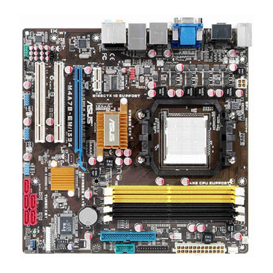
Page 18: Motherboard Overview
Motherboard overview 1.5.1 Placement direction When installing the motherboard, ensure that you place it into the chassis in the correct orientation. The edge with external ports goes to the rear part of the chassis as indicated in the image below. 1.5.2 Screw holes Place eight screws into the holes indicated by circles to secure the motherboard to the... -
Page 19: Motherboard Layout
Serial port connector (10-1 pin COM1) 1-22 16. Optical drive audio connector (4-pin CD) 1-26 IDE connector (40-1 pin PRI_IDE) 1-24 17. PCI / PCIe x 1 / PCIe x 16 slots 1-17 System panel connector (20-8 pin PANEL) 1-28 ASUS M4A78-EM/1394... -
Page 20: Central Processing Unit (Cpu)
Central Processing Unit (CPU) This motherboard comes with an AM2+ / AM2 socket designed for AMD Phenom™ x4 / ® Phenom™ x3 / Athlon™ x2 / Athlon™ / Sempron™ processors. It also supports AM3 CPUs including Phenom™ II / Athlon™ x4 / Athlon™ x3 / Athlon™ x2 processors. The AM2+ / AM2 socket has a different pinout from the 940-pin socket designed for the AMD Opteron™... - Page 21 Connect the CPU fan cable to the CPU_FAN connector on the motherboard. DO NOT forget to connect the CPU fan connector! Hardware monitoring errors can occur if you fail to plug this connector. ASUS M4A78-EM/1394...
-
Page 22: Installing The Heatsink And Fan
1.6.2 Installing the heatsink and fan Ensure that you use only AMD -certified heatsink and fan assembly. ® To install the CPU heatsink and fan: Place the heatsink on top of the installed CPU, ensuring that the heatsink fits properly on the retention module base. -
Page 23: System Memory
The motherboard comes with four Double Data Rate 2 (DDR2) Dual Inline Memory Modules (DIMM) sockets. The figure illustrates the location of the DDR2 DIMM sockets: Channel Sockets Channel A DIMM_A1 and DIMM_A2 Channel B DIMM_B1 and DIMM_B2 ASUS M4A78-EM/1394 1-11... -
Page 24: Memory Configurations
1.7.2 Memory configurations You may install 512MB, 1GB, 2GB and 4GB unbuffered ECC and non-ECC DDR2 DIMMs into the DIMM sockets. • You may install varying memory sizes in Channel A and Channel B. The system maps the total size of the lower-sized channel for the dual-channel configuration. Any excess memory from the higher-sized channel is then mapped for single-channel operation. - Page 25 F2-6400CL5D-2GBNQ Heat-Sink Package G.SKILL · · · 2048MB G.SKILL F2-6400CL4D-4GBPK Heat-Sink Package G.SKILL · · · 2048MB G.SKILL F2-6400CL5D-4GBPQ Heat-Sink Package G.SKILL · · 4096MB G.SKILL F2-6400CL6Q-16GMQ Heat-Sink Package · · · (continued on the next page) ASUS M4A78-EM/1394 1-13...
- Page 26 DDR2-800MHz capability DIMM socket support Size Vendor Part No. SS/DS Chip NO. Chip Brand (Optional) 1024MB GEIL GB22GB6400C4DC GL2L64M088BA30EB GEIL · · · 1024MB GEIL GB22GB6400C5DC GL2L64M088BA30EB GEIL · · · 1024MB GEIL GB24GB6400C4QC GL2L64M088BA30EB GEIL · · · 1024MB GEIL GB24GB6400C5QC GL2L64M088BA30EB...
- Page 27 • C*: Supports two pairs of modules inserted into both the yellow slots and the black slots as two pairs of dual-channel memory configuration. Visit the ASUS website at www.asus.com for the latest QVL. ASUS M4A78-EM/1394 1-15...
-
Page 28: Installing A Dimm
1.7.3 Installing a DIMM Unplug the power supply before adding or removing DIMMs or other system components. Failure to do so can cause severe damage to both the motherboard and the components. Press the retaining clips outward to DDR2 DIMM notch unlock a DDR2 DIMM socket. -
Page 29: Expansion Slots
This motherboard supports PCI Express x1 network cards, SCSI cards, and other cards that comply with the PCI Express specifications. 1.8.5 PCI Express x16 slot This motherboard supports a PCI Express x16 graphics card that complies with the PCI Express specifications. ASUS M4A78-EM/1394 1-17... -
Page 30: Jumpers
Jumpers Clear RTC RAM (CLRTC) This jumper allows you to clear the Real Time Clock (RTC) RAM in CMOS. You can clear the CMOS memory of date, time, and system setup parameters by erasing the CMOS RTC RAM data. The onboard button cell battery powers the RAM data in CMOS, which include system setup information such as system passwords. -
Page 31: Connectors
8-channel configurations, the function of this port becomes Front Speaker Out. Microphone port (pink). This port connects to a microphone. Side Speaker Out port (gray). This port connects to the side speakers in the 8-channel audio configuration. ASUS M4A78-EM/1394 1-19... - Page 32 Refer to the audio configuration table below for the function of the audio ports in the 2, 4, 6, or 8-channel configuration. Audio 2, 4, 6, or 8-channel configuration Headset Port 4-channel 6-channel 8-channel 2-channel Light Blue Line In Line In Line In Line In Lime...
- Page 33 1280 x 1080p • To play HD DVD or Blu-Ray disc, ensure to use HDCP compliant devices and software. USB 2.0 ports 5 and 6. These two 4-pin Universal Serial Bus (USB) ports are for USB 2.0 devices. ASUS M4A78-EM/1394 1-21...
-
Page 34: Internal Connectors
DO NOT forget to connect the fan cables to the fan connectors. Insufficient air flow inside the system may damage the motherboard components. These are not jumpers! DO NOT place jumper caps on the fan connectors. Only the CPU fan supports the ASUS Q-Fan feature. 1-22 Chapter 1: Product introduction... - Page 35 The system may become unstable or may not boot up if the power is inadequate. LPT connector (26-1 pin LPT) The LPT (Line Printing Terminal) connector supports devices such as a printer. LPT is standardized as IEEE 1284, which is the parallel port interface on IBM PC-compatible computers. ASUS M4A78-EM/1394 1-23...
- Page 36 IDE connector (40-1 pin PRI_IDE) The onboard IDE connector is for Ultra DMA 133/100/66 signal cable. There are three connectors on each Ultra DMA 133/100/66 signal cable: blue, black, and gray. Connect the blue connector to the motherboard’s IDE connector, then select one of the following modes to configure your devices: Drive jumper setting Mode of device(s)
- Page 37 This connector is for an IEEE 1394a port. Connect the IEEE 1394a module cable to this connector, then install the module to a slot opening at the back of the system chassis. Never connect a USB cable to the IEEE 1394a connector. Doing so will damage the motherboard! ASUS M4A78-EM/1394 1-25...
- Page 38 USB connectors (10-1 pin USB78, USB910, USB1112) These connectors are for USB 2.0 ports. Connect the USB module cable to any of these connectors, then install the module to a slot opening at the back of the system chassis. These USB connectors comply with USB 2.0 specification that supports up to 480Mbps connection speed.
- Page 39 Front Panel Select item in the BIOS setup to [HD Audio]. If you want to connect an AC'97 front panel audio module to this connector, set the item to [AC97]. By default, this connector is set to [HD Audio]. See section 2.4.4 Onboard Devices Configuration for details. ASUS M4A78-EM/1394 1-27...
-
Page 40: System Panel Connector (20-8 Pin Panel)
System panel connector (20-8 pin PANEL) This connector supports several chassis-mounted functions. • System power LED (2-pin PLED) This 2-pin connector is for the system power LED. Connect the chassis power LED cable to this connector. The system power LED lights up when you turn on the system power, and blinks when the system is in sleep mode. -
Page 41: Software Support
The contents of the Support DVD are subject to change at any time without notice. Visit the ASUS website at www.asus.com for updates. To run the Support DVD Place the Support DVD into the optical drive. - Page 42 1-30 Chapter 1: Product introduction...
-
Page 43: Chapter 2: Bios Information
BIOS in the future. Copy the original motherboard BIOS using the ASUS Update utility. 2.1.1 ASUS Update utility The ASUS Update is a utility that allows you to manage, save, and update the motherboard BIOS in Windows environment. ®... -
Page 44: Asus Ez Flash 2 Utility
Follow the onscreen instructions to complete the updating process. 2.1.2 ASUS EZ Flash 2 utility The ASUS EZ Flash 2 feature allows you to update the BIOS without using an OS-based utility. Before you start using this utility, download the latest BIOS file from the ASUS website at www.asus.com. -
Page 45: Asus Crashfree Bios 3 Utility
2.1.3 ASUS CrashFree BIOS 3 utility The ASUS CrashFree BIOS 3 is an auto recovery tool that allows you to restore the BIOS file when it fails or gets corrupted during the updating process. You can update a corrupted BIOS file using the motherboard Support DVD or a USB flash disk that contains the updated BIOS file. -
Page 46: Bios Setup Program
• The BIOS setup screens in this chapter are for reference only. They may not exactly match what you see on your screen. • Visit the ASUS website at www.asus.com to download the latest BIOS file for this motherboard. Chapter 2: BIOS information... -
Page 47: Bios Menu Screen
At the bottom right corner of a menu screen are the navigation keys for that particular menu. Use the navigation keys to select items in the menu and change the settings. Some of the navigation keys differ from one screen to another. ASUS M4A78-EM/1394... -
Page 48: Menu Items
2.2.4 Menu items The highlighted item on the menu bar displays the specific items for that menu. For example, selecting Main shows the Main menu items. The other items (Advanced, Power, Boot, Tools, and Exit) on the menu bar have their respective menu items. -
Page 49: Main Menu
IDE device type. Select [CDROM] if you are specifically configuring a CD-ROM drive. Select [ARMD] (ATAPI Removable Media Device) if your device is either a ZIP, LS-120, or MO drive. Configuration options: [Not Installed] [Auto] [CDROM] [ARMD] This item only appears in the Primary IDE Master/Slave menus. ASUS M4A78-EM/1394... -
Page 50: Sata Configuration
LBA/Large Mode [Auto] Enables or disables the LBA mode. Setting this item to [Auto] enables the LBA mode if the device supports this mode, and if the device was not previously formatted with LBA mode disabled. Configuration options: [Disabled] [Auto] Block (Multi-Sector Transfer) M [Auto] Enables or disables data multi-sectors transfers. -
Page 51: Advanced Menu
Allows you to select the GPU Overclocking. Configuration options: [Auto] [Manual] The following item appears only when the GPU Overclocking item is set to [Manual]. GPU Engine Clock [500] Allows you to set the GPU engine clock. The valid value is between 150 and 999. ASUS M4A78-EM/1394... - Page 52 PCIE Overclocking [Auto] Allows you to select the PCIE Overclocking. Configuration options: [Auto] [Manual] The following item appears only when the PCIE Overclocking item is set to [Manual]. PCIE Clock [100] Allows you to set the PCIE clock. The valid value is between 100 and 150. Processor Frequency Multiplier [Auto] Allows you to select the processor frequency.
-
Page 53: Cpu Configuration
Allows you to enable the bank memory interleaving. Configuration options: [Disabled] [Auto] Channel Interleaving [Disabled] Allows you to enable the channel memory interleaving. Configuration options: [Disabled] [Address bits 6] [Address bits 12] [XOR of Address bits [20:16,6] ] [XOR of Address bits [20:16,9] ] ASUS M4A78-EM/1394 2-11... -
Page 54: Ecc Configuration
Enable Clock to All DIMMs [Disabled] Enables or disables clock to all DIMMs. Configuration options: [Disabled] [Enabled] MemClk Tristate C3/ATLVID [Disabled] Enables or disables the MemClk Tristate C3/ALTVID. Configuration options: [Disabled] [Enabled] Memory Hole Remapping [Enabled] Enables or disables the memory remapping around memory hole. Configuration options: [Disabled] [Enabled] DCT Unganged Mode [Auto] Allows you to enable or disable unganged DRAM mode. -
Page 55: Onboard Devices Configuration
When set to [No], BIOS configures all the devices in the system. When set to [Yes] and if you install a Plug and Play operating system, the operating system configures the Plug and Play devices not required for boot. Configuration options: [No] [Yes] ASUS M4A78-EM/1394 2-13... -
Page 56: Usb Configuration
2.4.6 USB Configuration The items in this menu allows you to change the USB-related features. Select an item then press <Enter> to display the configuration options. The Module Version and USB Devices Enabled items show the auto-detected values. If no USB device is detected, the item shows None. -
Page 57: Apm Configuration
Allows you to enable or disable RTC to generate a wake event. When this item is set to Enabled, the items RTC Alarm Date, RTC Alarm Hour, RTC Alarm Minute, and RTC Alarm Second appear with set values. Configuration options: [Disabled] [Enabled] ASUS M4A78-EM/1394 2-15... -
Page 58: Hw Monitor Configuration
Select Ignored if you do not wish to display the detected voltage output. Smart Q-Fan Function [Enabled] Allows you to enable or disable the ASUS Q-Fan feature that smartly adjusts the fan speeds for more efficient system operation. Configuration options: [Disabled] [Enabled] Fan Auto Mode Start Voltage [5.0V]... -
Page 59: Boot Device Priority
This allows you to enable or disable the full screen logo display feature. Configuration options: [Disabled] [Enabled] Set this item to [Enabled] to use the ASUS MyLogo 2™ feature. AddOn ROM Display Mode [Force BIOS] Sets the display mode for option ROM. Configuration options: [Force BIOS] [Keep Current] Bootup Num-Lock [On] Allows you to select the power-on state for the NumLock. -
Page 60: Change User Password
The message “Password Installed” appears after you successfully set your password. To change the supervisor password, follow the same steps as in setting a supervisor password. To clear the supervisor password, select the Change Supervisor Password then press <Enter> twice. The message “Password Uninstalled” appears. If you forget your BIOS password, you can clear it by erasing the CMOS Real Time Clock (RTC) RAM. -
Page 61: Tools Menu
AI NET2 2.7.1 ASUS EZ Flash 2 Allows you to run ASUS EZ Flash 2. When you press <Enter>, a confirmation message appears. Use the left/right arrow key to select between [Yes] or [No], then press <Enter> to confirm your choice. -
Page 62: Exit Menu
Exit menu The Exit menu items allow you to load the optimal or failsafe default values for the BIOS items, and save or discard your changes to the BIOS items. BIOS SETUP UTILITY Main Advanced Power Boot Tools Exit Exit Options Exit system setup Exit system setup after saving the...
Need help?
Do you have a question about the M4A78-EM 1394 and is the answer not in the manual?
Questions and answers