Table of Contents
Advertisement
Advertisement
Chapters
Table of Contents

Related Manuals for Asus M4A78 PRO - Motherboard - ATX


Summary of Contents for Asus M4A78 PRO - Motherboard - ATX
- Page 1 M4A78 PRO...
- Page 2 Product warranty or service will not be extended if: (1) the product is repaired, modified or altered, unless such repair, modification of alteration is authorized in writing by ASUS; or (2) the serial number of the product is defaced or missing.
-
Page 3: Table Of Contents
Welcome! ..................1-1 Package contents ................. 1-1 Special features ................1-1 1.3.1 Product highlights ............1-1 1.3.2 Innovative ASUS features ..........1-2 Before you proceed ..............1-4 Motherboard overview ..............1-5 1.5.1 Placement direction ............1-5 1.5.2 Screw holes ..............1-5 1.5.3... -
Page 4: Contents
2.1.1 Creating a bootable floppy disk ........2-1 2.1.2 ASUS Update utility ............2-2 2.1.3 ASUS EZ Flash 2 utility ........... 2-3 2.1.4 AFUDOS utility ..............2-4 2.1.5 ASUS CrashFree BIOS 3 utility ........2-5 BIOS setup program ..............2-6 2.2.1... - Page 5 Boot Device Priority ............2-24 2.7.2 Boot Settings Configuration .......... 2-24 2.7.3 Security ................. 2-25 Tools menu ................. 2-26 2.8.1 ASUS EZ Flash 2 ............2-26 2.8.2 Express Gate ............... 2-26 2.8.3 ASUS O.C. Profile ............2-27 2.8.4 AI NET 2................ 2-27...
-
Page 6: Notices
Notices Federal Communications Commission Statement This device complies with Part 15 of the FCC Rules. Operation is subject to the following two conditions: • This device may not cause harmful interference, and • This device must accept any interference received including interference that may cause undesired operation. -
Page 7: Safety Information
Safety information Electrical safety • To prevent electrical shock hazard, disconnect the power cable from the electrical outlet before relocating the system. • When adding or removing devices to or from the system, ensure that the power cables for the devices are unplugged before the signal cables are connected. If possible, disconnect all power cables from the existing system before you add a device. -
Page 8: Conventions Used In This Guide
Refer to the following sources for additional information and for product and software updates. ASUS websites The ASUS website provides updated information on ASUS hardware and software products. Refer to the ASUS contact information. Optional documentation Your product package may include optional documentation, such as warranty flyers, that may have been added by your dealer. -
Page 9: M4A78 Pro Specifications Summary
*Due to AMD CPU limitation, DDR2 1066 is supported by AM2+ / AM3 CPUs for one DIMM per channel only. Refer to www.asus.com or this user manual for the Memory QVL (Qualified Vendors Lists). ** Due to OS limitation, when installing total memory of 4GB capacity or more, Windows 32-bit operation system may only recognize less than 3GB. - Page 10 - ASUS Anti-Surge Protection ASUS Green Design: - ASUS EPU - ASUS AI Nap ASUS Quiet Thermal Solution: - ASUS Fanless Design: Feather heatsink solution - ASUS Q-Fan 2 ASUS EZ DIY - ASUS Express Gate - ASUS Q-Connector - ASUS CrashFree BIOS 3 - ASUS O.C.
- Page 11 - PCIe frequency tuning from 100MHz to 150MHz at 1MHz increment Overclocking protection: - ASUS C.P.R. (CPU Parameter Recall) Rear panel I/O ports 1 x PS/2 keyboard port (purple) 1 x PS/2 mouse port (green) 1 x S/PDIF Out (Optical)
- Page 12 M4A78 PRO specifications summary BIOS features 8 Mb Flash ROM, AMI BIOS, PnP, DMI 2.0, WfM2.0, SM BIOS 2.5, ACPI 2.0a, ASUS EZ Flash 2 Support DVD contents Drivers Express Gate ASUS PC Probe II ASUS Update AMD OverDrive Utility (AOD)
-
Page 13: Chapter 1 Product Introduction
® The motherboard delivers a host of new features and latest technologies, making it another standout in the long line of ASUS quality motherboards! Before you start installing the motherboard, and hardware devices on it, check the items in your package with the list below. -
Page 14: Innovative Asus Features
Innovative ASUS features ASUS Power Solution ASUS 4+1 Phase Power Design To fully unleash the next-generation AM3 CPU’s potential, ASUS M4A78 PRO motherboard has adopted a brand-new 4-phase VRM power design. It delivers high power efficiency and supreme overclocking ability. -
Page 15: Asus Turbov
O.C. settings in different scenarios. ASUS Turbo Key ASUS Turbo Key allows the user to turn the PC power button into a physical overclocking button. After the easy setup, Turbo Key can boost performances without interrupting ongoing work or games—with just one... -
Page 16: Before You Proceed
ON, in sleep mode, or in soft-off mode. This is a reminder that you should shut down the system and unplug the power cable before removing or plugging in any motherboard component. The illustration below shows the location of the onboard LED. ASUS M4A78 PRO... -
Page 17: Motherboard Overview
Motherboard overview 1.5.1 Placement direction When installing the motherboard, ensure that you place it into the chassis in the correct orientation. The edge with external ports goes to the rear part of the chassis as indicated in the image below. 1.5.2 Screw holes Place nine (9) screws into the holes indicated by circles to secure the motherboard to the... -
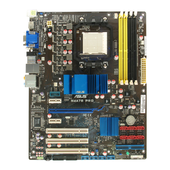
Page 18: Motherboard Layout
CPU, Chassis and Power Fan connectors (4-pin CPU_FAN, 3-pin CHA_FAN1, 3-pin 1-22 PWR_FAN) DDR2 DIMM slots 1-10 Serial ATA connectors (7-pin SATA1-6) 1-25 IDE connector (40-1 pin PRI_IDE) 1-24 System panel connector (10-1 pin PANEL) 1-26 Onboard LED (SB_PWR) 10. Chassis intrusion connector (4-1 pin CHASSIS) 1-22 11. USB device wake-up (3-pin USBPW1-4, USBPW5-8, USBPW9-12) 1-18 12. USB connectors (10-1 pin USB56, USB78, USB910, USB1112) 1-27 13. Clear RTC RAM (CLRTC) 1-17 14. Floppy disk drive connector (34-1 pin FLOPPY) 1-27 15. Digital audio connector (4-1 pin SPDIF_OUT) 1-28 16. Optical drive audio in connector (4-pin CD) 1-28 17. Front panel audio connector (10-1 pin AAFP) 1-29 18. Serial port connector (10-1 pin COM1) 1-29 ASUS M4A78 PRO... -
Page 19: Central Processing Unit (Cpu)
Central Processing Unit (CPU) The motherboard comes with a CPU socket designed for AMD AM3 Phenom™ II / ® Athlon™ X4 / Athlon™ X3 / Athlon™ X2 processors and AM2+ / AM2 Phenom™ X4 / Phenom™ X3 / Athlon™ X2 / Athlon™ / Sempron™ processors. The CPU socket is not compatible with AMD Opteron™... -
Page 20: Installing The Heatsink And Fan
• If you purchased a separate CPU heatsink and fan assembly, ensure that a Thermal Interface Material is properly applied to the CPU heatsink or CPU before you install the heatsink and fan assembly. CPU Fan CPU Heatsink Retention bracket Retention Module Base Retention bracket lock ASUS M4A78 PRO... - Page 21 Your boxed CPU heatsink and fan assembly should come with installation instructions for the CPU, heatsink, and the retention mechanism. If the instructions in this section do not match the CPU documentation, follow the latter. Attach one end of the retention bracket to the retention module base. Align the other end of the retention bracket to the retention module base.
-
Page 22: System Memory
• For system stability, use a more efficient memory cooling system to support a full memory load (4 DIMMs) or overclocking condition. 1-10 ASUS M4A78 PRO... -
Page 23: System Stability
M4A78 PRO Motherboard Qualified Vendors Lists (QVL) DDR2-1066MHz capability DIMM socket support (Optional) Chip Vendor Part No. Size Chip No. Brand A-DATA Heat-Sink Package 2GB (kit of 2) AD21066E001GU 5-5-5-15 • A-DATA Heat-Sink Package 4GB (kit of 2) AD21066E002GU 5-5-5-15 •... - Page 24 Heat-Sink Package GEIL • • • HYMP564U64CP8-S5 AB 512MB HY5PS12821CFP-S5 Hynix • • • HYMP 512U64CP8-S5 AB HY5PS12821CFPS5 Hynix • • • Kingmax KLDD48F-B8KB5 KKB8FFBGXF-CFA-25U Kingmax • • • Kingmax KLDE88F-B8KB5 KKB8FFBGXF-CFA-25U Kingmax • • • 1-12 ASUS M4A78 PRO...
- Page 25 DDR2-800MHz capability (continued) DIMM socket support (Optional) Chip Vendor Part No. Size Chip No. Brand Kingston KHX6400D2LLK2/1GN 512MB Heat-Sink Package Kingston • • • Kingston KVR800D2N5/ 512 512MB E5108AJBG-8E-E 0803A9082 Kingston • • • Kingston KVR800D2N6/ 512 512MB E5108AJBG-8E-E Elpida •...
- Page 26 ELIXIR • • N2TU 51280BE- ELIXIR M2Y1G64TU8HBOB-3C ELIXIR • • • 3C639009W1CF Leadmax LRMP 512U64A8-Y5 HY5PS12821CFP-Y5 C 702AA Hynix • • • Kingston KVR667D2E5/1G E5108AJBG-8E-E(ECC) Elpida • • • Kingston KVR667D2E5/2G NT5TU128M8DE-3C(ECC) Elpida • • • 1-14 ASUS M4A78 PRO...
-
Page 27: Installing A Dimm
Dual-channel memory configuration. • C*: Supports four modules inserted into both the yellow slots and the black slots as two pairs of Dual-channel memory configuration. Visit the ASUS website for the latest QVL. 1.7.3 Installing a DIMM Unplug the power supply before adding or removing DIMMs or other system components. -
Page 28: Expansion Slots
This motherboard supports PCI Express x1 network cards, SCSI cards, and other cards that comply with the PCI Express specifications. 1.8.5 PCI Express x16 slot This motherboard supports a PCI Express x16 graphics card that complies with the PCI Express specifications. 1-16 ASUS M4A78 PRO... -
Page 29: Jumpers
Jumpers Clear RTC RAM (CLRTC) This jumper allows you to clear the Real Time Clock (RTC) RAM in CMOS. You can clear the CMOS memory of date, time, and system setup parameters by erasing the CMOS RTC RAM data. The onboard button cell battery powers the RAM data in CMOS, which include system setup information such as system passwords. -
Page 30: Keyboard Power (3-Pin Kbpwr)
CPU, DRAM in slow refresh, power supply in reduced power mode). The USBPW1-4 jumpers are for the rear USB ports. The USBPW5-8 and USBPW9-12 jumpers are for the internal USB connectors that you connect to additional USB ports. 1-18 ASUS M4A78 PRO... -
Page 31: Connectors
1.10 Connectors 1.10.1 Rear panel connectors PS/2 mouse port. This port is for a PS/2 mouse. Video Graphics Adapter (VGA) port This 15-pin port is for a VGA monitor or other VGA-compatible devices. LAN (RJ-45) port. This port allows Gigabit connection to a Local Area Network (LAN) through a network hub. - Page 32 ® software (not supporting video acceleration) Best resolution File format Windows XP Windows Vista Non-protected clips 1920 x 1080p 1920 x 1080p HD-DVD 1920 x 1080p 1280 x 1080p Blu-Ray 1280 x 1080p 1280 x 1080p 1-20 ASUS M4A78 PRO...
- Page 33 Troubleshooting on HDTV overscaling or underscaling: If your desktop is extending beyond the viewable display area or the desktop or image is not filling the entire display area while using the onboard HDMI out port and the HDMI cable, you can resize the desktop appearing on your HDTV screen.
-
Page 34: Internal Connectors
These are not jumpers! DO NOT place jumper caps on the fan connectors. Only the CPU_FAN and CHA_FAN1 connectors support the ASUS Q FAN 2 feature. Chassis intrusion connector (4-1 pin CHASSIS) This connector is for a chassis-mounted intrusion detection sensor or switch. Connect one end of the chassis intrusion sensor or switch cable to this connector. - Page 35 The system may become unstable or may not boot up if the power is inadequate. • If you are uncertain about the minimum power supply requirement for your system, refer to the Recommended Power Supply Wattage Calculator at http://support.asus. com/PowerSupplyCalculator/PSCalculator.aspx?SLanguage=en-us for details. Chapter 1: Product introduction...
- Page 36 This prevents incorrect insertion when you connect the IDE cable. • Use the 80-conductor IDE cable for Ultra DMA 133/100/66 IDE devices. If any device jumper is set as “Cable-Select”, ensure that all other device jumpers have the same setting. 1-24 ASUS M4A78 PRO...
-
Page 37: Serial Ata Connectors (7-Pin Sata1-6)
Serial ATA connectors (7-pin SATA1-6) These connectors are for the Serial ATA signal cables for Serial ATA 3Gb/s hard disk and optical disk drives. The Serial ATA 3Gb/s is backward compatible with Serial ATA 1.5Gb/s specification. The data transfer rate of the Serial ATA 3Gb/s is faster than the standard parallel ATA with 133 MB/s (Ultra DMA133). -
Page 38: System Panel Connector (10-1 Pin Panel)
BIOS settings. Pressing the power switch for more than four seconds while the system is ON turns the system OFF. Reset button (2-pin RESET) • This 2-pin connector is for the chassis-mounted reset button for system reboot without turning off the system power. 1-26 ASUS M4A78 PRO... -
Page 39: Usb Connectors (10-1 Pin Usb56, Usb78, Usb910, Usb1112)
USB connectors (10-1 pin USB56, USB78, USB910, USB1112) These connectors are for USB 2.0 ports. Connect the USB module cable to any of these connectors, then install the module to a slot opening at the back of the system chassis. These USB connectors comply with USB 2.0 specification that supports up to 480 Mbps connection speed. -
Page 40: Digital Audio Connector (4-1 Pin Spdif_Out)
This connector allows you to receive stereo audio input from sound sources such as a CD-ROM, TV tuner, or MPEG card. Digital audio connector (4-1 pin SPDIF_OUT) This connector is for an additional Sony/Philips Digital Interface (S/PDIF) ports. The S/PDIF module is purchased separately. 1-28 ASUS M4A78 PRO... -
Page 41: Front Panel Audio Connector (10-1 Pin Aafp)
Front panel audio connector (10-1 pin AAFP) This connector is for a chassis-mounted front panel audio I/O module that supports either High Definition Audio or AC`97 audio standard. Connect one end of the front panel audio I/O module cable to this connector. •... - Page 42 ASUS Q-Connector (system panel) You can use the ASUS Q-Connector to connect/disconnect chassis front panel cables in a few steps. Refer to the instructions below to install the ASUS Q-Connector. Connect the front panel cables to the ASUS Q-Connector. Refer to the labels on the Q-Connector to...
-
Page 43: Software Support
ASUS website at www.asus.com for updates. • For detailed software instructions, see the Manual menu in the Support DVD or download the latest software manual from the ASUS website at www.asus.com. To run the Support DVD Place the Support DVD to the optical drive. The DVD automatically displays the Drivers menu if Autorun is enabled in your computer. - Page 44 1-32 ASUS M4A78 PRO...
-
Page 45: Chapter 2 Bios Information
Save a copy of the original motherboard BIOS file to a bootable floppy disk or a USB flash disk in case you need to restore the BIOS in the future. Copy the original motherboard BIOS using the ASUS Update or AFUDOS utilities. 2.1.1... -
Page 46: Asus Update Utility
2.1.2 ASUS Update utility The ASUS Update is a utility that allows you to manage, save, and update the motherboard BIOS in Windows environment. ® • ASUS Update requires an Internet connection either through a network or an Internet Service Provider (ISP). -
Page 47: Asus Ez Flash 2 Utility
2.1.3 ASUS EZ Flash 2 utility The ASUS EZ Flash 2 feature allows you to update the BIOS without having to use a bootable floppy disk or a DOS-based utility. Download the latest BIOS file from the ASUS website at www.asus.com. -
Page 48: Afudos Utility
• Obtain the AFUDOS utility (afudos.exe) from the bundled support DVD and the latest BIOS file from the ASUS website at www.asus.com. • We recommend that you write the BIOS filename on a piece of paper. You will need to key in the exact BIOS filename at the DOS prompt later. -
Page 49: Asus Crashfree Bios 3 Utility
2.1.5 ASUS CrashFree BIOS 3 utility The ASUS CrashFree BIOS 3 is an auto recovery tool that allows you to restore the BIOS file when it fails or gets corrupted during the updating process. You can update a corrupted BIOS file using the motherboard support DVD, a floppy disk, or a USB flash disk that contains the updated BIOS file. -
Page 50: Bios Setup Program
• The BIOS setup screens shown in this section are for reference purposes only, and may not exactly match what you see on your screen. • Visit the ASUS website at www.asus.com to download the latest BIOS file for this motherboard. -
Page 51: Bios Menu Screen
• The BIOS setup screens shown in this chapter are for reference purposes only, and may not exactly match what you see on your screen. • Visit the ASUS website at www.asus.com to download the latest BIOS information. Chapter 2: BIOS setup... -
Page 52: Navigation Keys
General Help F10 Save and Exit ESC Exit fit on the screen. Press the <Up> / <Down> v02.61 (C)Copyright 1985-2008, American Megatrends, Inc. arrow keys or <Page Up> /<Page Down> keys Scroll bar to display the other items on the screen. Pop-up window ASUS M4A78 PRO... -
Page 53: Main Menu
Main menu When you enter the BIOS Setup program, the Main menu screen appears, giving you an overview of the basic system information. Refer to section 2.2.1 BIOS menu screen for information on the menu screen items and how to navigate through them. BIOS SETUP UTILITY Main Ai Tweaker Advanced Power Boot Tools Exit System Time... -
Page 54: Sata 1-6
When set to [Disabled], the data transfer from and to the device occurs one sector at a time. Configuration options: [Disabled] [Auto] PIO Mode [Auto] Selects the PIO mode. Configuration options: [Auto] [0] [1] [2] [3] [4] 2-10 ASUS M4A78 PRO... -
Page 55: Storage Configuration
DMA Mode [Auto] Selects the DMA mode. Configuration options: [Auto] SMART Monitoring [Auto] Sets the Smart Monitoring, Analysis, and Reporting Technology. Configuration options: [Auto] [Disabled] [Enabled] 32Bit Data Transfer [Enabled] Enables or disables 32-bit data transfer. Configuration options: [Disabled] [Enabled] 2.3.6 Storage Configuration This menu allows you to configure the SATA devices. -
Page 56: Ai Tweaker Menu
Use the <+> and <-> keys to adjust the PCIE frequency. You can also type the desired PCIE frequency using the numeric keypad. The values range from 100 to 150. 2.4.2 DRAM Frequency Control [Auto] Allows you to select the DRAM frequency control method. Configuration options: [Auto] [Manual] 2-12 ASUS M4A78 PRO... -
Page 57: Ht Link Speed
DRAM Frequency [667MHz] This item appears only when you set the Dram Frequency Control item to [Manual] and allows you to manually set the Dram frequency. Configuration options: [667MHz] [800MHz] [1067MHz] CPU/NB Frequency [Auto] This item appears only when you set the AI Overclocking item to [Manual] and allows selection of the CPU frequency multiplier. - Page 58 Configuration options: [Auto] [DCT 0] [DCT 1] [Both] The following sub-items appear only when you set the DCT0/DCT1 Strength Config. item to [DCT 0] or [Both]. DCT0:CKE drive strength. [Auto] Configuration options: [Auto] [1x] [1.25x] [1.5x] [2x] 2-14 ASUS M4A78 PRO...
-
Page 59: Processor Voltage
DCT0:CS/ODT drive strength. [Auto] Configuration options: [Auto] [1x] [1.25x] [1.5x] [2x] DCT0:Address/Command drive strength. [Auto] Configuration options: [Auto] [1x] [1.25x] [1.5x] [2x] DCT0:MEMCLK drive strength. [Auto] Configuration options: [Auto] [0.75x] [1x] [1.25x] [1.5x] DCT0:Data drive strength. [Auto] Configuration options: [Auto] [0.75x] [1x] [1.25x] [1.5x] DCT0:DQS drive strength. -
Page 60: Cpu Vdda Voltage
Set to [Disabled] to enhance PCIE overclocking ability or [Enabled] for EMI control. Configuration options: [Disabled] [Enabled] 2.4.14 SB Clock Spread Spectrum [Disabled] We recommend that you leave this item to its default setting for system stability. Configuration options: [Disabled] [Enabled] 2-16 ASUS M4A78 PRO... -
Page 61: Advanced Menu
Advanced menu The Advanced menu items allow you to change the settings for the CPU and other system devices. Be cautious when changing the settings of the Advanced menu items. Incorrect field values can cause the system to malfunction. BIOS SETUP UTILITY Main Ai Tweaker Advanced Power Boot Tools Exit CPU Configuration Configure CPU. -
Page 62: Chipset
Disables or sets the L2/L3 Cache BG Scrub. This item allows the L2/L3 Data Cache RAM to be corrected when idle. Configuration options: [Disabled] [40ns] [80ns] [160ns] [320ns] [640ns] [1.28us] [2.56us] [5.12us] [10.2us] [20.5us] [41.0us] [81.9us] [163.8us] [327.7us] [655.4us] [1.31ms] [2.62ms] [5.24ms] [10.49ms] [20.97ms] [42.00ms] [84.00ms] 2-18 ASUS M4A78 PRO... -
Page 63: Internal Graphics Configuration
RS780 Configuration Internal Graphics Configuration This menu allows you to change the onboard graphics configuration settings. Select an item then press <Enter> to display the sub-menu. Internal Graphics Mode [UMA] Allows you to set the frame buffer location for the onboard GPU. Configuration options: [Disable] [UMA] UMA Frame Buffer Size [Auto] This item appears only when you set the Internal Graphics Mode item to [UMA]. -
Page 64: Onboard Devices Configuration
Onboard LAN Boot ROM [Disabled] Allows you to enable or disable the onboard LAN Boot ROM. Configuration options: [Disabled] [Enabled] Serial Port1 Address [3F8/IRQ4] Allows you to select the Serial Port1 base address. Configuration options: [Disabled] [3F8/IRQ4][2F8/IRQ3] [3E8/IRQ4] [2E8/IRQ3] 2-20 ASUS M4A78 PRO... -
Page 65: Usb Configuration
2.5.4 USB Configuration The items in this menu allows you to change the USB-related features. Select an item then press <Enter> to display the configuration options. The Module Version and USB Devices Enabled items show the auto-detected values. If no USB device is detected, the item shows None. USB Support [Enable] Allows you to enable or disable the USB Functions. -
Page 66: Apm Configuration
Allows you to enable or disable RTC to generate a wake event. When this item is set to [Enabled], the items RTC Alarm Date and RTC Alarm Time appear with set values. Configuration options: [Disabled] [Enabled] 2-22 ASUS M4A78 PRO... -
Page 67: Hardware Monitor
2.6.6 Hardware Monitor CPU/MB Temperature [xxxºC/xxxºF] The onboard hardware monitor automatically detects and displays the motherboard and CPU temperatures. Select [Ignored] if you do not wish to display the detected temperatures. CPU Fan / Chassis Fan 1 / Power Fan Speed [xxxxRPM] or [Ignored] The onboard hardware monitor automatically detects and displays the CPU, chassis, and power fan speed in rotations per minute (RPM). -
Page 68: Boot Menu
This allows you to enable or disable the full screen logo display feature. Configuration options: [Disabled] [Enabled] Set this item to [Enabled] to use the ASUS MyLogo 2™ feature. AddOn ROM Display Mode [Force BIOS] Sets the display mode for option ROM. -
Page 69: Security
Hit ‘DEL’ Message Display [Enabled] When set to [Enabled], the system displays the message Press DEL to run Setup during POST. Configuration options: [Disabled] [Enabled] 2.7.3 Security The Security menu items allow you to change the system security settings. Select an item then press <Enter>... -
Page 70: Tools Menu
2.8.1 ASUS EZ Flash 2 Allows you to run ASUS EZ Flash 2. When you press <OK>, a confirmation message appears. Use the left/right arrow key to select between [Yes] or [No], then press <OK> to confirm your choice. -
Page 71: Asus O.c. Profile
The first time wizard will run again when you enter the Express Gate environment after clearing its settings. 2.8.3 ASUS O.C. Profile This item allows you to store or load multiple BIOS settings. Add Your CMOS Profile. Allows you to save the current BIOS file to the BIOS Flash. In the Name sub-item, type your profile name and press <Enter>, and then choose a profile number to save your CMOS... -
Page 72: Exit Menu
When you select this option or if you press <F5>, a confirmation window appears. Select OK to load default values. Select Exit & Save Changes or make other changes before saving the values to the non-volatile RAM. 2-28 ASUS M4A78 PRO...
Need help?
Do you have a question about the M4A78 PRO - Motherboard - ATX and is the answer not in the manual?
Questions and answers