Table of Contents
Advertisement
Advertisement
Table of Contents

Related Manuals for X10 SC1200


Summary of Contents for X10 SC1200
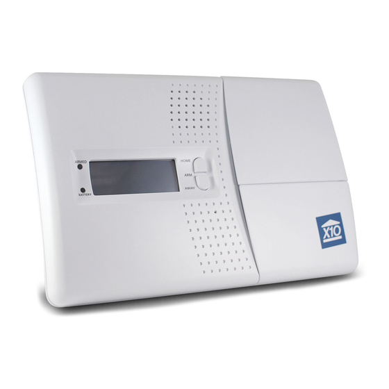
- Page 1 Supervised Security System Model SC1200 Owner’s Manual...
-
Page 2: Table Of Contents
TV experiencing the interference. When there’s an alarm ................34 Controlling Lights and Appliances ..............35 If necessary, contact www.x10.com for additional suggestions. Setting up Optional Lamp Modules .............36 Operation from an Outside Telephone ............37 Replacing Batteries ..................38... -
Page 3: Introduction
Locating the Security Console protects an indoor area. The Keychain Remote Control is used for arming and disarming the system. It can also turn lights on and off (requires X10 Modules). All sensors and remotes incorporate random digital security coding. -
Page 4: Attaching The Cables
Security System. The power supply contains circuitry required to control X10 Modules, so you CANNOT replace it If you don’t want to wall mount the console, you can insert the included rubber plugs into with a regular 8V DC power supply. -
Page 5: Overview
0-9 Used for all number entries. 12:00 am On Used to send an X10 On message or to enter am in a time. Off Used to send an X10 Off message or to enter pm in a time. When you enter the PIN the display shows the First Level of the menu at step 1, below. - Page 6 Installation Installation First Menu Level Sub-menus After pressing a menu up/down button and entering the PIN, the First level menu is Once you’ve arrived at your desired fi rst level menu and pressed OK, you can select the displayed, as shown below: sub-menus under that menu item.
-
Page 7: Registering Door/Window Sensors
Installation Installation Initializing Keychain Remotes Initializing Door/Window Sensors Press and hold the ARM button on the Keychain remote for 3-4 seconds Remove the screw from the front of the Door/Window Sensor and install and then release it. This initializes the remote and picks a random code 2 AAA alkaline batteries inside. -
Page 8: Removing Door/Window Sensors
Installation Installation Installing the Door/Window Sensors Now move the magnet away from the Door/Window Sensor. The Console acknowledges that it has been registered with a chime and by displaying ZONE 1 SET. Note, if the Sensors you purchased are Repeat this for any other Door/Window Sensors you want to register. The display different from shown here, refer to the increments to ZONE 2 SET, etc., as you install more Door Window Sensors. -
Page 9: Removing Motion Detectors
Installation Installation Initializing Motion Detectors Now simply press the TEST button on the back of the Motion Detector (or turn the unit over so that it sees motion). The Console will acknowledge that it has been registered by displaying (for example) ZONE 3 SET. Remove the cover on the front of the Motion Detector and install 2 AAA alkaline batteries in the compartment. -
Page 10: Installing The Motion Detector
Installation Installation Installing the Motion Detector Hard-Wired Inputs You can also connect two hard-wired magnetic contact switches to the console. • Attach the Motion Detector to a wall at a height of 5 to 6 ft. using the mounting bracket and screws provided. -
Page 11: Setting The Clock
Installation Installation Setting the Clock Setting the phone numbers Press either of the Menu up/down buttons (under the lid to the bottom right of the display). Press either of the Menu up/down buttons (under the lid to the bottom right of the display). The display then shows ENTER PIN (Personal Identifi... - Page 12 Installation Installation Recording your outgoing phone message Press 1 for RECORD , then press OK. The display shows: Press either of the Menu up/down buttons (under the lid to the bottom right of the display). PLEASE WAIT The display then shows ENTER PIN (Personal Identifi cation Number) in the top line. ENTER PIN Then: 12:00 am...
-
Page 13: Clearing The Memory
Note, choose a PIN that you are not likely to forget (a birthday, for example). If you forget CLEAR ALL REMOTES your PIN you will not be able use the system. If you do forget your PIN contact www.x10. CLEAR ALL TIMERS com to fi... -
Page 14: Setting The Options
Installation Installation Setting Options Setting Delays Press either of the Menu up/down buttons (under the lid to the bottom right of the display). Press either of the Menu up/down buttons (under the lid to the bottom right of the display). The display then shows ENTER PIN (Personal Identifi... -
Page 15: Setting The Timers
Installation Installation Setting Timers To enter a new timer you must be on the NEW TIMER screen. Then press OK. The display shows UNIT NUMBER on the top line. Using the number keys, enter a valid number (1-16) and press OK. Press either of the Menu up/down buttons (under the lid to the bottom right of the display). - Page 16 Installation Installation Reviewing/Canceling Timers You can cycle through (Review) your stored timers by pressing the up or down Menu buttons. This will show the stored timers in the form below Press either of the Menu up/down buttons (under the lid to the bottom right of the display). 12ON 12:34am The display then shows ENTER PIN (Personal Identifi...
-
Page 17: Using The System
Using the system Using the system Arming the system If there’s a problem Press ARM HOME on the Console to arm all Door/Window Sensors instantly. Motion If a door or window is open and you try to arm the system the display looks as below. Detectors will not trip the system when it is armed in the ARM HOME mode. -
Page 18: When There's An Alarm
X10 Modules that are set to the Security LIGHTCODE you set in the Console. (See step Lights (set to the two security codes) fl ash on and off (if you set up X10 Modules). See 4 on page 26). The B buttons control modules set to the next sequential number. I.E. if you page 36. -
Page 19: Operation From An Outside Telephone
If the PIN is entered correctly it says “PIN accepted”. If wrong it says “Error.” If you then press 4, then * on the touch tone phone, it says “4 On” and turns on any X10 Module(s) set to Unit Code 4 (and the same Housecode as the Console is set to). -
Page 20: Battery Information
Battery Information Battery Information General Door/Window Sensors and Motion Detectors Door/Window Sensors, Motion Detectors and Keychain remotes are designed to operate Battery Replacement for approximately one year when fi tted with the appropriate batteries. Since operating If a zone has not reported in to the Console during the last four hours, the display will show conditions vary from installation to installation however, it is recom mended that all batteries PROBLEM and the appropriate zone number when you try to arm the system. -
Page 21: Troubleshooting
Troubleshooting Troubleshooting PROBLEM SOLUTION PROBLEM SOLUTION If the system does not arm. • Check that the indicator on the Remote If you hear a repetitive trouble alarm when Check the Console’s display. If a door or turns on when you press ARM. you try to arm the system, and it does not window is open, its zone # will indicate Replace the batteries and reregister the... - Page 22 Troubleshooting Troubleshooting PROBLEM SOLUTION PROBLEM SOLUTION If you do not hear a beep from the You open a door or window and the alarm With the Console NOT armed check that • Check that the system is armed. Console when you register a Door/ does not trip.
- Page 23 PIN on the Console. one (1) year from the original date of purchase at retail. X10 agrees to repair or replace, at its sole discretion, a defective X10 product if returned to X10 within the warranty period and with proof of purchase.
-
Page 24: Expanding Your System
Expanding Your System Expanding Your System The X10 Security System can fl ash lights on and off when the alarm trips. You connect Control an incandescent ceiling light, closet light, etc., with the convenient Screw- in Lamp Module LM15A. the lights you want it to control to X10 Lamp Modules and Wall Switch Modules (sold separately). - Page 25 This adds another level of protection for you home – not only will your Increase the viewable area of your security system trip if someone breaks in, but you can also use X10 cameras with camera by 400%. The standard...
- Page 27 X10.com, a Division of X10 Wireless Technology, Inc. 400 Forge Way, Suite 409-412, Rockaway, NJ 07866 SC1200 -12/10 Supervised Security System...
Need help?
Do you have a question about the SC1200 and is the answer not in the manual?
Questions and answers