
Subscribe to Our Youtube Channel
Related Manuals for Leviton N1000-006


Summary of Contents for Leviton N1000-006
- Page 1 ___________________________ User Guide N1000-006 Document Release Aug. 2006 Revision A...
- Page 2 Leviton will not be responsible for any loss of use time or subsequent damages should any of the equipment fail during the warranty period, but agrees only to repair or replace defective equipment returned to its plant in Tualatin, Oregon.
-
Page 3: Table Of Contents
Table of Contents Chapter 1 Introduction..........1 About the Console ............2 Features.............. 2 Specifications ............2 Warnings ! ............2 Console Controls..........3 Rear Panel ............4 Using this Guide ............4 Text Conventions ..........4 Terminology Definitions........4 Contacting Technical Support ......... - Page 4 N1000-006 User Guide Page ii...
-
Page 5: Chapter 1 Introduction
Chapter 1 Introduction This chapter is intended to orient you to the console and user guide. The following sections are covered: • About the Console • Features • Specifications • Warnings • Console Controls • Rear Panel • Using this Guide •... -
Page 6: About The Console
Chapter 1 Introduction About the Console Thank You for purchasing the Leviton N1000-006 lighting control console! The N1000-006 is a compact yet powerful console, perfectly designed for small size applications. To optimize the performance of this product, please read this user guide carefully to familiarize yourself with the basic operations of the unit. -
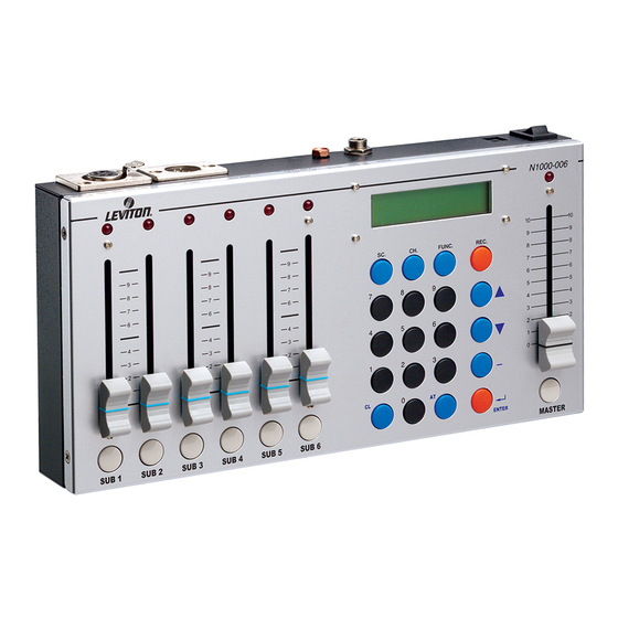
Page 7: Console Controls
Console Controls 9 10 Channel / Sub Level LED Channel / Sub Fader Channel / Sub Bump Button Clear Key Alpha-Numeric Keypad At Key Thru Key Enter Key Down Select Key Up Select Key Master Black Out Button Master Fader Master Level LED Record Key Function Key... -
Page 8: Rear Panel
. The current standard for dimmer protocols is known as DMX 512. The amount of dimmers available for control depends on your model. For example, with the N3008 model, you can control up to eight dimmers. N1000-006 User Guide Page 4... -
Page 9: Contacting Technical Support
You may also call us during regular business hours at 1-800-959-6004. Please have the console model number and serial number available when you call. Contact Information Leviton Lighting Management Systems Division 20497 SW Teton, Tualatin, OR 97062 Mailing Address: PO Box 2210... - Page 10 Chapter 1 Introduction N1000-006 User Guide Page 6...
-
Page 11: Chapter 2 Operation
Chapter 2 Operation The following sections are covered in this chapter: • Console Setup • Power On • Internal Battery Operation • Auto Memory • Console Reset • Master Fader and Bump Button • Setting Channel Levels • Setting Channel Levels using Faders •... -
Page 12: Console Setup
Chapter 2 Operation Console Setup Power On 1. Plug the 12V DC adapter into a 110V AC mains outlet. 2. Plug the DC power connector into the DC power jack located on the rear of the console. 3. Plug the DMX signal cable attached to you dimmers into the DMX OUT connector on the rear of the console. -
Page 13: Setting Channel Levels
Setting Channel Levels Setting Channel Levels using Faders Individual channel levels can be adjusted directly with the six channel faders. To give the user channel intensity feedback, channel intensity LED’s are provided above the faders. The six faders correspond sequentially to whatever range of channels that are selected and shown in the LCD. -
Page 14: Setting Channel Levels Using The Keypad
Chapter 2 Operation Setting Channel Levels using the Keypad Individual channel levels can be also be set using the keypad. See the example below to set channel 7 to 80%: Procedure: Notes: 1. Raise the Master Fader to 100% (full) Make sure the console is turned On. -
Page 15: Channel Bump Buttons
Channel Bump Buttons Pressing the bump buttons located below each fader allows individual channels to change quickly to full intensity (100%) while in CH. SET mode. Clearing Channel Levels There are two ways to clear the levels of all channels while in CH. SET mode : Procedure: Notes: 1. -
Page 16: Scenes
Chapter 2 Operation Scenes As mentioned earlier, a scene is a recorded lighting look that is comprised of individual channel levels. With this console, up to 46 scenes may be recorded for future playback. There are two methods of recording and recalling scenes. The first way is by recording a scene to one of the six submasters. -
Page 17: Recording Scenes To Scene Memory
Recording Scenes to Scene Memory In this example, we will set levels on channels one through six and record them into scene one. Procedure: Notes: 1. Raise the Master Fader to 100% (full) 2. Press the [FUNC] key. The LCD displays: >CH SETTING SUB MASTER 3. -
Page 18: Recalling Submaster Scenes
2. Press the [ ] key to select the sub function: CH SETTING >SUB MASTER 3. Press [ENTER] to select sub: SUB MASTER 1--6 LEVITON CORP. 4. Press and Hold [SUB1] key: Sub level is output at 100%. LOAD SUBSCENE 1 -OR- 5. -
Page 19: Modifying Submaster Memory
Recalling Memory Scenes (Con’t) Procedure: Notes: 3. Press [ENTER] to select scene: SUB MASTER 1--6 LEVITON CORP. 4. Press the [SC] key: LOAD SCENE KEYIN SC 1...40 5. Press [1]: LOAD SCENE 6. Press [ENTER]: Scene is output at recorded levels. -
Page 20: Modifying Scene Memory
Chapter 2 Operation Modifying Submaster Memory (Con’t) 6. Press [ENTER] to complete the operation: SUB MASTER 1--6 LEVITON CORP. Modifying Scene Memory After you have recorded channel levels into a scene, you can modify the channel levels. See the following example. -
Page 21: Clearing Scene Levels
Clearing Scene Levels There are two ways to clear the levels of a scene while in SUB MASTER mode: Procedure: Notes: 1. Press the [CL] and [SC] keys at the same time - OR - 1. Lower the Master Fader to 0%, then Press the [MASTER] key. -
Page 22: Chases
Chapter 2 Operation Chases As mentioned earlier in this guide, a chase is a series (sequence of steps) of individual channel levels or pre-recorded scenes that can be played back in a continuous loop. With this console, you can run two different types of chases;... -
Page 23: Channel Chase + Scene
Channel Chase + Scene A channel chase can be executed while a scene is active in the background. Please follow below. 1. Press the [SC] key while the chase is running: LOAD SCENE KEYIN SC 1...40 2. Enter [1] or whatever scene # desired: LOAD SCENE 3. -
Page 24: Chase Fade
Chapter 2 Operation Chase Fade A channel or sub chase sequence can either instantaneously bump (Fade Off) or gently fade (Fade On) between steps. Follow the channel chase example below to change the fade type. The same method applies for a sub chase. Procedure: Notes: 1. -
Page 25: Auto Fade
Auto Fade The auto fade function allows a single channel or range of channels to automatically fade from 0 to 100% and back in a continuous fashion. 21 speeds are available, ranging from 0.1 seconds to 1 minute. Auto Fade a Single Channel Procedure: Notes: 1. -
Page 26: Dmx In
Chapter 2 Operation Auto Fade a Range of Channels (Con’t) Procedure: Notes: 4. Press [CH] [1] [-] [6]: AUTO FADE 3sec CH 1 -- 6-> 40% 5. Press [ENTER] to select the speed: To change the speed, use the [ ] [ ] keys . AUTO FADE 20sec CH 1 -- 6->... -
Page 27: Emergency Backup Scene Fade Time
Recording a Emergency Backup Scene (Con’t) 2. Press the [ENTER] key: CH.SET 1--- 1 -----= 0% 3. Press [CH] [1] [-] [6] [AT] [100] [ENTER]: Or use Keypad to set levels. CH.SET 1--- 1 - 6-= 100% 4. Press [ ] six times to select the backup scene function: Backup DMX Scene 1:YES , 2:NO 5. - Page 28 Chapter 2 Operation Recording a Snapshot Scene (Con’t) 4. Enter a name using the keypad: Keypad numbers 0 - 9 represent the alphabet. See Alpha-Numeric chart below. Name: ABC KEYIN ENGLISH 5. Press [ENTER] Scene is recorded. Alpha-Numeric chart N1000-006 Page 24...
- Page 30 Copyright © 2006 Leviton Manufacturing Company Incorporated. All Rights Reserved. Information contained herein is subject to change without notice. Document Release Aug. 2006. Rev. A P/N DI-000-N1000-05A Leviton Lighting Management Systems Division 20497 SW Teton, Tualatin, OR 97062 Mailing Address:...
Need help?
Do you have a question about the N1000-006 and is the answer not in the manual?
Questions and answers