Table of Contents
Advertisement
Your miter saw has been engineered and manufactured to our high standard for dependability, ease of operation, and
operator safety. When properly cared for, it will give you years of rugged, trouble-free performance.
WARNING:
To reduce the risk of injury, the user must read and understand the operator's manual before using
this product.
Thank you for your purchase.
SAVE THIS MANUAL FOR FUTURE REFERENCE
OPERATOR'S MANUAL
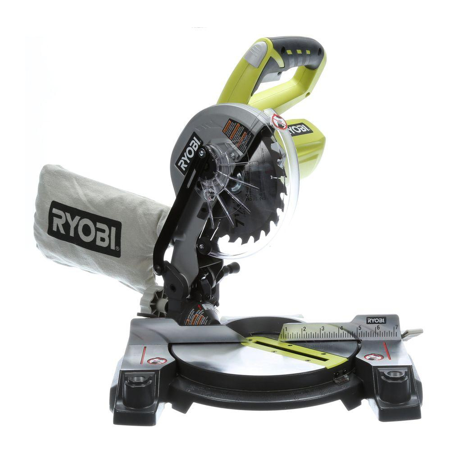
7-1/4 in., 18 Volt
Compound Miter Saw
P551
bATTERy ANd CHARGER
SOLd SEPARATELy
Advertisement
Table of Contents

Related Manuals for Ryobi P551


Summary of Contents for Ryobi P551
- Page 1 OPERATOR’S MANUAL 7-1/4 in., 18 Volt Compound Miter Saw P551 bATTERy ANd CHARGER SOLd SEPARATELy Your miter saw has been engineered and manufactured to our high standard for dependability, ease of operation, and operator safety. When properly cared for, it will give you years of rugged, trouble-free performance.
-
Page 2: Table Of Contents
The replacement power tool will be covered by the limited warranty for the balance of the two year period from the date of the original purchase. WHAT THIS WARRANTy COVERS: This warranty covers all defects in workmanship or materials in your RYOBI power ®... -
Page 3: General Safety Rules
GENERAL SAFETy RULES USE RECOMMENdEd ACCESSORIES. Consult the WARNING: operator’s manual for recommended accessories. The use of improper accessories may result in injury. Read and understand all instructions. Failure to follow NEVER STANd ON TOOL. Serious injury could occur if all instructions listed below, may result in electric shock, the tool is tipped or if the cutting tool is unintentionally fire and/or serious personal injury. -
Page 4: Specific Safety Rules
GENERAL SAFETy RULES NEVER START A TOOL WHEN ANy ROTATING COM- FOR USE WITH 18 V NICKEL-CAdMIUM ANd 18 V PONENT IS IN CONTACT WITH THE WORKPIECE. LITHIUM-ION bATTERy PACKS, see tool/appliance/ battery pack/charger correlation supplement 987000-432. dO NOT OPERATE A TOOL WHILE UNdER THE INFLUENCE OF dRUGS, ALCOHOL, OR ANy ... - Page 5 SPECIFIC SAFETy RULES NEVER hand hold a workpiece that is too small to be ALWAyS STAy ALERT! Do not allow familiarity (gained clamped. Keep hands clear of the cutting area. from frequent use of your saw) to cause a careless mistake.
-
Page 6: Symbols
SyMbOLS The following signal words and meanings are intended to explain the levels of risk associated with this product. SyMbOL SIGNAL MEANING Indicates an imminently hazardous situation, which, if not avoided, will result dANGER: in death or serious injury. Indicates a potentially hazardous situation, which, if not avoided, could result WARNING: in death or serious injury. -
Page 7: Glossary Of Terms
GLOSSARy OF TERMS Anti-Kickback Pawls (flooring, radial arm, and table saws) Push blocks (jointer planers) A device which, when properly installed and maintained, Device used to feed the workpiece over the jointer planer is designed to stop the workpiece from being kicked back cutterhead during any operation. -
Page 8: Features
FEATURES PROdUCT SPECIFICATIONS Cutting Capacity with Miter at 0°/Bevel 0°: Maximum lumber sizes ..... 1-1/2 in. x 4-1/4 in. Arbor ................. 5/8 in. Cutting Capacity with Miter at 45°/Bevel 0°: Blade Diameter ............7-1/4 in. Maximum lumber sizes ......1-1/2 in. x 3 in. No Load Speed ........ -
Page 9: Know Your Compound Miter Saw
FEATURES KNOW yOUR COMPOUNd MITER SAW Lock See Figure 1. The safe use of this product requires an understanding of Miter the information on the tool and in this operator’s manual as Lock Lever well as a knowledge of the project you are attempting. Before use of this product, familiarize yourself with all operating features and safety rules. -
Page 10: Tools Needed
FEATURES SWITCH TRIGGER switch See Figure 4. Lock The saw will not start until you depress the switch lock with your thumb then squeeze the switch trigger. To prevent unauthorized use of the compound miter saw, remove the battery pack, and lock the switch in the off position. To lock switch padLock the switch, install a padlock (not included) through the hole... -
Page 11: Loose Parts List
LOOSE PARTS LIST The following items are included with your compound miter saw: Dust Bag Rear Bracket/Carrying Handle Work Clamp Operator’s Manual Blade Wrench work cLaMp dust bLade wrench rear bracket/ carrYing handLe Fig. 6 WARNING: The use of attachments or accessories not listed might be hazardous and could cause serious personal injury. -
Page 12: Assembly
ASSEMbLy UNPACKING WARNING: This product requires assembly. To prevent accidental starting that could cause serious Carefully lift miter saw base from the carton by the “D” personal injury, always remove the battery pack from the handle and the saw base, and place it on a level work tool when assembling parts. -
Page 13: Mounting Holes
ASSEMbLy WARNING: dust Always make sure the compound miter saw is securely exhaust mounted to a workbench or an approved workstand. Failure port to heed this warning can result in serious personal injury. MOUNTING HOLES See Figure 8. If not using a stand, the saw should be mounted to a firm supporting surface such as a workbench. - Page 14 ASSEMbLy WORK CLAMP See Figure 10. The work clamp provides greater control by clamping the workpiece to the fence. It also prevents the workpiece from creeping toward the saw blade. This is very helpful when cutting compound miters. Depending on the cutting operation and the size of the workpiece, it may be necessary to use a C-clamp instead of the work clamp to secure the workpiece prior to making the cut.
- Page 15 ASSEMbLy TO INSTALL/REPLACE THE bLAdE See Figures 11 - 12. WARNING: A 7-1/4 in. blade is the maximum blade capacity of the saw. Never use a blade that is too thick to allow outer blade washer to engage with the flats on the spindle. Larger blades will come in contact with the blade guards, while thicker blades will prevent the blade bolt from se- curing the blade on the spindle.
- Page 16 ASSEMbLy NOTE: Many of the illustrations in this manual show only Miter portions of the compound miter saw. This is intentional so Miter Lock fraMing that we can clearly show points being made in the illustra- tabLe Miter Lever square tions.
- Page 17 ASSEMbLy socket head screw(s) socket head Miter screw(s) Lock Miter Lever fence bLade fraMing Miter square tabLe view of bLade square with fence Miter Fig. 17 fence Fig. 16 SqUARING THE bLAdE TO THE FENCE Miter See Figures 16 - 19. fence ...
- Page 18 ASSEMbLy SqUARING THE bLAdE TO THE MITER TAbLE See Figures 20 - 23. beveL Remove the battery pack from the tool. Lock Pull the saw arm all the way down and engage the lock knob pin to hold the saw arm in transport position. ...
-
Page 19: Assembly
ASSEMbLy dANGER: Laser radiation. Avoid direct eye contact with light source. WARNING: Use of controls or adjustments or performance of pro- cedures other than those specified herein may result in hazardous radiation exposure. ALIGNING THE LASER GUIdE LINE See Figure 24. Draw a line on the workpiece. -
Page 20: Operation
This product will accept Ryobi One+ 18 V lithium-ion battery packs and Ryobi One+ 18 V nickel-cadmium battery packs. For optimum performance, use with Ryobi P100 or P104 battery packs. - Page 21 OPERATION bATTERy PROTECTION FEATURES cross cut Ryobi lithium-ion batteries are designed with features that protect the lithium-ion cells and maximize battery life. If the tool stops during use, release the trigger to reset and resume operation. If the tool still does not work, the battery needs to be recharged.
- Page 22 OPERATION Align cutting line on workpiece with edge of saw blade. indicator Grasp the stock firmly with one hand and secure it against point the fence. Use the optional work clamp or a C-clamp to secure the workpiece when possible. ...
- Page 23 OPERATION Before turning on the saw, perform a dry run of the cutting coMpound Miter cut operation just to make sure that no problems will occur when the cut is made. Grasp the saw handle firmly. Depress the switch lock with thumb then squeeze the switch trigger.
- Page 24 OPERATION Place the workpiece flat on the miter table with one edge securely against the fence. If the board is warped, place the convex side against the fence. If the concave edge of a board is placed against the fence, the board could collapse on the blade at the end of the cut, jamming the blade.
-
Page 25: Cutting Compound Miters
OPERATION CUTTING COMPOUNd MITERS To aid in making the correct settings, the compound angle setting chart below has been provided. Since compound cuts are the most difficult to accurately obtain, trial cuts should be made in scrap material, and much thought and planning made, prior to making the required cut. -
Page 26: Cutting Crown Molding
OPERATION CUTTING CROWN MOLdING When setting the bevel and miter angles for compound miters, remember that the settings are interdependent; changing This compound miter saw does an excellent job of cutting one angle changes the other angle as well. crown molding. In general, compound miter saws do a better Keep in mind that the angles for crown molding are very job of cutting crown molding than any other tool made. - Page 27 OPERATION bevel Angle Type of Cut Setting Left side, inside corner 1. Top edge of molding against fence 33.85° 2. Miter table set right 31.62° 3. Save left end of cut Right side, inside corner 1. Bottom edge of molding against fence 33.85°...
-
Page 28: Adjustments
AdJUSTMENTS POSITIVE STOP AdJUSTMENTS WARNING: See Figure 36. To prevent accidental starting that could cause serious NOTE: These adjustments were made at the factory and personal injury, always remove the battery pack from the normally do not require readjustment. tool when assembling parts. To adjust: ... - Page 29 NOTE: The laser should be on the left edge of the kerf. Once aligned, tighten the screw. unLock NOTE: If laser does not align correctly, return to your nearest Ryobi Authorized Service Center for repair. Lock TO AdJUST THE MITER LOCK LEVER See Figure 38.
-
Page 30: Maintenance
MAINTENANCE LUbRICATION WARNING: All of the bearings in this tool are lubricated with a sufficient amount of high grade lubricant for the life of the unit under When servicing, use only identical replacement parts. normal operating conditions. Therefore, no further lubrica- Use of any other parts may create a hazard or cause tion is required. - Page 31 NOTES...
- Page 32 When ordering repair parts, always give the following information: P551 • MODEL NUMBER • SERIAL NUMBER Ryobi is a registered trademark of Ryobi Limited and is used pursuant to a license granted by Ryobi Limited. ONE WORLd TECHNOLOGIES, INC. 1428 Pearman Dairy Road, Anderson, SC 29625 Phone 1-800-525-2579 www.ryobitools.com...
Need help?
Do you have a question about the P551 and is the answer not in the manual?
Questions and answers