Table of Contents
Advertisement
Advertisement
Table of Contents

Related Manuals for Asus M4A785-M - Motherboard - Micro ATX


Summary of Contents for Asus M4A785-M - Motherboard - Micro ATX
- Page 1 M4A785-M...
- Page 2 Product warranty or service will not be extended if: (1) the product is repaired, modified or altered, unless such repair, modification of alteration is authorized in writing by ASUS; or (2) the serial number of the product is defaced or missing.
-
Page 3: Table Of Contents
Welcome! ..................1-1 Package contents ................. 1-1 Special features ................1-1 1.3.1 Product highlights ............1-1 1.3.2 Innovative ASUS features ..........1-3 Before you proceed ..............1-5 Motherboard overview ..............1-6 1.5.1 Placement direction ............1-6 1.5.2 Screw holes ..............1-6 1.5.3... - Page 4 Chapter 2: BIOS information Managing and updating your BIOS ..........2-1 2.1.1 ASUS Update utility ............2-1 2.1.2 ASUS EZ Flash 2 ............2-2 2.1.3 ASUS CrashFree BIOS ........... 2-3 BIOS setup program ..............2-4 2.2.1 BIOS menu screen ............2-5 2.2.2...
- Page 5 Boot Device Priority ............2-18 2.6.2 Boot Settings Configuration .......... 2-18 2.6.3 Security ................. 2-19 Tools menu ................. 2-20 2.7.1 ASUS EZ Flash 2 ............2-20 2.7.2 Express Gate ..............2-21 2.7.3 AI NET 2................ 2-21 Exit menu ..................2-22...
-
Page 6: Notices
Complying with the REACH (Registration, Evaluation, Authorisation, and Restriction of Chemicals) regulatory framework, we published the chemical substances in our products at ASUS REACH website at http://green.asus.com/english/REACH.htm. DO NOT throw the motherboard in municipal waste. This product has been designed to enable proper reuse of parts and recycling. -
Page 7: Safety Information
Safety information Electrical safety • To prevent electric shock hazard, disconnect the power cable from the electric outlet before relocating the system. • When adding or removing devices to or from the system, ensure that the power cables for the devices are unplugged before the signal cables are connected. If possible, disconnect all power cables from the existing system before you add a device. -
Page 8: About This Guide
Operation safety • Before installing the motherboard and adding devices on it, carefully read all the manuals that came with the package. • Before using the product, ensure that all cables are correctly connected and the power cables are not damaged. If you detect any damage, contact your dealer immediately. •... -
Page 9: Conventions Used In This Guide
Refer to the following sources for additional information and for product and software updates. ASUS websites The ASUS website provides updated information on ASUS hardware and software products. Refer to the ASUS contact information. Optional documentation Your product package may include optional documentation, such as warranty flyers, that may have been added by your dealer. -
Page 10: M4A785-M Specifications Summary
** DDR2 1200(O.C.)/1066 is supported by AM3/AM2+ CPU only. *** Due to AM3/AM2+ CPU limitation, only one DDR2 1200(O.C.)/1066 is supported per channel. ****Refer to www.asus.com for the latest Memory QVL (Qualified Vendors List). ***** When you install a total memory of 4GB or more, Windows ®... - Page 11 Supports up to 12 USB 2.0/1.1 ports (6 ports at mid-board, 6 ports at the back panel) Realtek 8112L PCIe Gigabit LAN controller ® ASUS unique ASUS 4+1 Phase Power Design features ASUS EPU-4 Engine ASUS Express Gate ASUS Turbo Key ASUS Anti-Surge...
- Page 12 1 x User Manual Support DVD Drivers ASUS Update ASUS PC Probe II Anti-Virus software (OEM version) Form factor MicroATX form factor: 9.6 in x 9.6 in (24.4 cm x 24.4 cm) * Specifications are subject to change without notice.
-
Page 13: Chapter 1: Product Introduction
® The motherboard delivers a host of new features and latest technologies, making it another standout in the long line of ASUS quality motherboards! Before you start installing the motherboard, and hardware devices on it, check the items in your package with the list below. - Page 14 Phenom™ X4 / Phenom™ X3 / Athlon™ X2 / Athlon™ / ® Sempron™ processors (socket AM2+/AM2) This motherboard supports AMD Socket AM2+ multi-core processors. ® It features dual-channel DDR2 1066 memory support, data transfer rate up to 5200MT/s via HyperTransport™ 3.0 based system bus, and AMD ®...
-
Page 15: Innovative Asus Features
Internet without entering the Windows ® • ASUS Express Gate supports installation on SATA HDDs, USB HDDs and flash drives with at least 1.2GB free disk space. When installing it on USB HDDs or flash drives, connect the drives to the motherboard USB port before turning on the computer. -
Page 16: Asus Mylogo 2
BIOS file using the bundled support DVD or a USB flash disk that contains the BIOS file. ASUS EZ Flash 2 ASUS EZ Flash 2 allows you to update the BIOS from a USB flash disk before entering the OS. ASUS EPU ASUS EPU is a unique power saving technology that detects the current system loadings and adjusts the power consumption in real time. -
Page 17: Before You Proceed
This motherboard and its packaging comply with the European Union’s Restriction on the use of Hazardous Substances (RoHS). This is in line with the ASUS vision of creating environment-friendly and recyclable products/packaging to safeguard consumers’ health while minimizing the impact on the environment. -
Page 18: Motherboard Overview
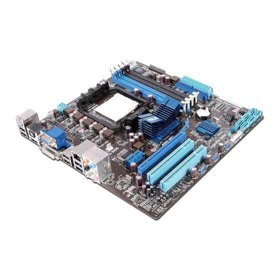
Motherboard overview 1.5.1 Placement direction When installing the motherboard, ensure that you place it into the chassis in the correct orientation. The edge with external ports goes to the rear part of the chassis as indicated in the image below. 1.5.2 Screw holes Place eight screws into the holes indicated by circles to secure the motherboard to the... -
Page 19: Motherboard Layout
12. USB connectors (10-1 pin USB78, USB910, 1-27 USB1112) LPT connector (26-1 pin LPT) 1-29 13. Digital audio connector (4-1 pin SPDIF_OUT) 1-28 IDE connector (40-1 pin PRI_IDE) 1-24 14. Front panel audio connector (10-1 pin AAFP) 1-28 ASUS M4A785-M... -
Page 20: Central Processing Unit (Cpu)
Central Processing Unit (CPU) The motherboard comes with an AM2+/AM2 socket designed for Phenom™ II / Athlon™ II / Phenom™ / Athlon™/ Sempron™ family processors (AM3/AM2+/AM2). The AM2/AM2+ socket has a different pinout from the 940-pin socket designed for the AMD Opteron™... - Page 21 Connect the CPU fan cable to the CPU_FAN connector on the motherboard. DO NOT forget to connect the CPU fan connector! Hardware monitoring errors can occur if you fail to plug this connector. ASUS M4A785-M...
-
Page 22: Installing The Heatsink And Fan
1.6.2 Installing the heatsink and fan Ensure that you use only AMD-certified heatsink and fan assembly. To install the CPU heatsink and fan: Place the heatsink on top of the installed CPU, ensuring that the heatsink fits properly on the retention module base. •... -
Page 23: System Memory
240-pin footprint compared to the 184-pin DDR DIMM. DDR2 DIMMs are notched differently to prevent installation on a DDR DIMM socket. The figure illustrates the location of the DDR2 DIMM sockets: Channel Sockets Channel A DIMM_A1 and DIMM_A2 Channel B DIMM_B1 and DIMM_B2 ASUS M4A785-M 1-11... -
Page 24: Memory Configurations
1.7.2 Memory configurations You may install 512MB, 1GB, 2GB, and 4GB unbuffered ECC and non-ECC DDR2 DIMMs into the DIMM sockets. • You may install varying memory sizes in Channel A and Channel B. The system maps the total size of the lower-sized channel for the dual-channel configuration. Any excess memory from the higher-sized channel is then mapped for single-channel operation. - Page 25 GB24GB6400C4QC GEIL GL2L64M088BA30EB • • • 1024MB GEIL GB24GB6400C5QC GEIL GL2L64M088BA30EB • • • 1024MB GEIL GE22GB800C4DC GEIL Heat-Sink Package • • • 1024MB GEIL GE22GB800C5DC GEIL Heat-Sink Package • • • (continued on the next page) ASUS M4A785-M 1-13...
- Page 26 DDR2-800MHz capability DIMM support Chip Size Vendor Part No. Chip NO. Brand 1024MB GEIL GE24GB800C4QC GEIL Heat-Sink Package • • • 1024MB GEIL GE24GB800C5QC GEIL Heat-Sink Package • • • 1024MB GEIL GX22GB6400DC GEIL Heat-Sink Package • • • 1024MB GEIL GX22GB6400UDC GEIL...
- Page 27 GEIL GX21GB5300SX GEIL Heat-Sink Package • • 2048MB GEIL GX22GB5300LX GEIL Heat-Sink Package • • 2048MB GEIL GX24GB5300LDC GEIL Heat-Sink Package • • • 512MB Kingmax KLCC28F-A8KB5 Kingmax KKEA88B4LAUG-29DX • • • (continued on the next page) ASUS M4A785-M 1-15...
- Page 28 • C*: Supports two pairs of modules inserted into both the blue slots and the black slots as two pairs of dual-channel memory configuration. Visit the ASUS website at www.asus.com for the latest QVL. 1-16 Chapter 1: Product introduction...
-
Page 29: Installing A Dimm
DIMM. Support the DIMM lightly with your fingers when pressing the retaining clips. The DIMM might get damaged when it flips out with extra force. DIMM notch Remove the DIMM from the socket. ASUS M4A785-M 1-17... -
Page 30: Expansion Slots
Expansion slots In the future, you may need to install expansion cards. The following sub-sections describe the slots and the expansion cards that they support. Unplug the power cord before adding or removing expansion cards. Failure to do so may cause you physical injury and damage motherboard components. -
Page 31: Jumpers
• You do not need to clear the RTC when the system hangs due to overclocking. For system failure due to overclocking, use the CPU Parameter Recall (C.P.R) feature. Shut down and reboot the system so the BIOS can automatically reset parameter settings to default values. ASUS M4A785-M 1-19... -
Page 32: Connectors
1.10 Connectors 1.10.1 Rear panel ports PS/2 Keyboard/Mouse Combo port (purple). This port is for a PS/2 keyboard or mouse. Optical S/PDIF_OUT port. This port connects to an external audio output device via an optical S/PDIF cable. VGA port. This 15-pin port is for a VGA monitor or other VGA-compatible devices. LAN (RJ-45) port. - Page 33 Dual display outputs Supported Not supported DVI + D-Sub • DVI + HDMI • HDMI + D-Sub • • During POST, only the monitor connected to the D-Sub port has display. The dual display function works only under Windows. ASUS M4A785-M 1-21...
- Page 34 Playback of HD DVD and Blu-ray discs • For better playback quality, we recommend that you follow the system requirements listed below. Suggested list Athlon 4400+ ® DIMM DDR2 800 (1GB or higher) BIOS setup Frame Buffer Size – 256MB or higher Best resolution File format Windows...
-
Page 35: Internal Connectors
The system may become unstable or may not boot up if the power is inadequate. • If you are uncertain about the minimum power supply requirement for your system, refer to the Recommended Power Supply Wattage Calculator at http://support.asus. com/PowerSupplyCalculator/PSCalculator.aspx?SLanguage=en-us for details. ASUS M4A785-M... - Page 36 IDE connector (40-1 pin PRI_IDE) The onboard IDE connector is for Ultra DMA 133/100/66 signal cable. There are three connectors on each Ultra DMA 133/100/66 signal cable: blue, black, and gray. Connect the blue connector to the motherboard’s IDE connector, then select one of the following modes to configure your devices: Drive jumper setting Mode of device(s)
- Page 37 • Due to Windows XP limitation, Windows XP may not recognize the USB floppy disk ® ® drive. • For more details on RAID/AHCI, refer to the RAID/AHCI Supplementary Guide included in the folder named Manual in the support DVD. ASUS M4A785-M 1-25...
-
Page 38: System Panel Connector (20-8 Pin Panel)
System panel connector (20-8 pin PANEL) This connector supports several chassis-mounted functions. • System power LED (2-pin PLED) This 2-pin connector is for the system power LED. Connect the chassis power LED cable to this connector. The system power LED lights up when you turn on the system power, and blinks when the system is in sleep mode. - Page 39 The connector is for a serial (COM) port. Connect the serial port module cable to the connector, then install the module to a slot opening at the back of the system chassis. The serial port module is purchased separately. ASUS M4A785-M 1-27...
- Page 40 Digital audio connector (4-1 pin SPDIF_OUT) This connector is for an additional Sony/Philips Digital Interface (S/PDIF) port. Ensure that the audio device of Sound playback is VIA High Definition Audio (the name may be different based on the OS). Go to Start > Control Panel > Sounds and Audio Devices >...
- Page 41 These are not jumpers! DO NOT place jumper caps on the fan connectors. Only the 4-pin CPU fan supports the ASUS Q-Fan feature. LPT connector (26-1 pin LPT) The LPT (Line Printing Terminal) connector supports devices such as a printer. LPT is standardized as IEEE 1284, which is the parallel port interface on IBM PC-compatible computers.
-
Page 42: Software Support
The contents of the Support DVD are subject to change at any time without notice. Visit the ASUS website at www.asus.com for updates. To run the Support DVD Place the Support DVD into the optical drive. -
Page 43: Chapter 2: Bios Information
BIOS in the future. Copy the original motherboard BIOS using the ASUS Update utility. 2.1.1 ASUS Update utility The ASUS Update is a utility that allows you to manage, save, and update the motherboard BIOS in Windows environment. ®... -
Page 44: Asus Ez Flash 2
Follow the onscreen instructions to complete the updating process. 2.1.2 ASUS EZ Flash 2 The ASUS EZ Flash 2 feature allows you to update the BIOS without using an OS-based utility. Before you start using this utility, download the latest BIOS file from the ASUS website at www.asus.com. -
Page 45: Asus Crashfree Bios
2.1.3 ASUS CrashFree BIOS The ASUS CrashFree BIOS is an auto recovery tool that allows you to restore the BIOS file when it fails or gets corrupted during the updating process. You can restore a corrupted BIOS file using the motherboard support DVD or a removable device that contains the updated BIOS file. -
Page 46: Bios Setup Program
• The BIOS setup screens in this chapter are for reference only. They may not exactly match what you see on your screen. • Visit the ASUS website at www.asus.com to download the latest BIOS file for this motherboard. Chapter 2: BIOS information... -
Page 47: Bios Menu Screen
At the bottom right corner of a menu screen are the navigation keys for that particular menu. Use the navigation keys to select items in the menu and change the settings. Some of the navigation keys differ from one screen to another. ASUS M4A785-M... -
Page 48: Menu Items
2.2.4 Menu items The highlighted item on the menu bar displays the specific items for that menu. For example, selecting Main shows the Main menu items. The other items (Advanced, Power, Boot, Tools, and Exit) on the menu bar have their respective menu items. -
Page 49: Main Menu
IDE/SATA device type. Select [CDROM] if you are specifically configuring a CD-ROM drive. Select [ARMD] (ATAPI Removable Media Device) if your device is either a ZIP, LS-120, or MO drive. Configuration options: [Not Installed] [Auto] [CDROM] [ARMD] This item only appears in the Primary IDE Master/Slave, SATA5/6 menus. ASUS M4A785-M... -
Page 50: Sata Configuration
LBA/Large Mode [Auto] Enables or disables the LBA mode. Setting this item to [Auto] enables the LBA mode if the device supports this mode, and if the device was not previously formatted with LBA mode disabled. Configuration options: [Disabled] [Auto] Block (Multi-Sector Transfer) M [Auto] Enables or disables data multi-sectors transfers. -
Page 51: System Information
The items and configuration options in this menu may vary depending on the AMD CPU type. CPU Overclocking [Auto] Selects the CPU overclocking options to achieve desired CPU internal frequency. Configuration options: [Manual] [Auto] [Overclock Profile] [Test Mode] ASUS M4A785-M... - Page 52 The following item only appears when you set CPU Overclocking to [Manual]. CPU/HT Reference Clock (MHz) [200] Sets the CPU/HT Reference Clock. Configuration options: [Min.=200] [Max.=550] The following item only appears when you set CPU Overclocking to [Overclock Profile]. Overclock Options [Auto] Selects the overclocking profile.
- Page 53 [Auto] Configuration options: [Auto] [1 CLK] [2 CLK] [3 CLK] [4 CLK] tWTR [Auto] Configuration options: [Auto] [1 CLK] [2 CLK] [3 CLK] tWRWR [Auto] Configuration options: [Auto] [1 CLK] [2 CLK] [3 CLK] [4 CLK] ASUS M4A785-M 2-11...
-
Page 54: Cpu Configuration
tRDRD [Auto] Configuration options: [Auto] [3 CLK] [4 CLK] [5 CLK] tRFC0/1/2/3 [Auto] Configuration options: [Auto] [75ns] [105ns] [127.5ns] [195ns] [327.5ns] Memory Over Voltage [Auto] Sets the memory over voltage. The values range from 1.5000V to 2.4450V with a 0.0150V increment. -
Page 55: Chipset
GFX0: primary video controller on a PCIe x16 slot GPP: primary video controller on a PCIe x1 slot IGFX: onboard VGA port PCI: primary video controller on a PCI slot UMA Frame Buffer Size [Auto] Configuration options: [Auto] [32MB] [64MB] [128MB] [256MB] [512MB] ASUS M4A785-M 2-13... -
Page 56: Onboard Device Configuration
Surround View [Auto] Disables or enables the Surround View function. Configuration options: [Auto] [Disabled] [Enabled] This item becomes user-configurable when you install an ATI graphics card into the PCIe x16 slot. Frame Buffer Location [Above 4G] Configuration options: [Below 4G] [Above 4G] AMD 785 HDMI Audio [Enabled] Enables or disables AMD 785 HDMI audio. -
Page 57: Pcipnp
Sets the maximum time that the BIOS waits for the USB storage device to initialize. Configuration options: [10 Sec] [20 Sec] [30 Sec] [40 Sec] Emulation Type [Auto] Allows you to set the emulation type. Configuration options: [Auto] [Floppy] [Forced FDD] [Hard Disk] [CDROM] ASUS M4A785-M 2-15... -
Page 58: Power Menu
Power menu The Power menu items allow you to change the settings for the Advanced Configuration and Power Interface (ACPI) and the Advanced Power Management (APM). Select an item then press <Enter> to display the configuration options. BIOS SETUP UTILITY Main Advanced Power... -
Page 59: Hw Monitor Configuration
Select [Ignored] if you do not want the detected voltage to be displayed. Smart Q-FAN Function [Disabled] Enables or disables the ASUS Q-Fan feature that smartly adjusts the CPU fan speed for more efficient system operation. Configuration options: [Disabled] [Enabled] 2.5.6... -
Page 60: Boot Menu
Configuration options: [Removable Dev.] [Hard Drive] [ATAPI CD-ROM] [Disabled] • To select the boot device during system startup, press <F8> when ASUS Logo appears. • To access Windows OS in Safe Mode, do any of the following: ®... -
Page 61: Security
View Only allows access but does not allow change to any field. Limited allows changes only to selected fields, such as Date and Time. Full Access allows viewing and changing all the fields in the Setup utility. ASUS M4A785-M 2-19... -
Page 62: Tools Menu
(C)Copyright 1985-2009, American Megatrends, Inc. 2.7.1 ASUS EZ Flash 2 Allows you to run ASUS EZ Flash 2. When you press <Enter>, a confirmation message appears. Use the left/right arrow key to select between [Yes] or [No], then press <Enter> to confirm your choice. -
Page 63: Express Gate
2.7.2 Express Gate [Auto] Enables or disables the ASUS Express Gate feature. ASUS Express Gate is a unique instant-on environment that provides quick access to the Internet and Skype. Configuration options: [Enabled] [Disabled] [Auto] Enter OS Timer [10 Seconds] Sets countdown duration that the system waits at the Express Gate’s first screen before starting Windows or other installed OS. -
Page 64: Exit Menu
Exit menu The Exit menu items allow you to load the optimal or failsafe default values for the BIOS items, and save or discard your changes to the BIOS items. BIOS SETUP UTILITY Main Advanced Power Boot Tools Exit Exit Options Exit system setup Exit system setup after saving the...
Need help?
Do you have a question about the M4A785-M - Motherboard - Micro ATX and is the answer not in the manual?
Questions and answers