Advertisement
Available languages
Available languages
APPLICATION
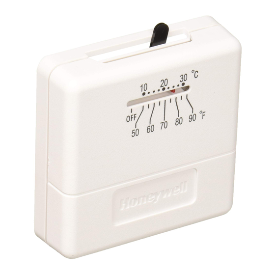
The T812 and TS812 Thermostats are low voltage,
controls for heat only, cool only or heating and cooling
systems. See Table 1.
Table 1. Model Descriptions.
Model
Voltage
T812A
24 Vac
T812B
12 Vdc
T812C
24 Vac
T812D
24 Vac
TS812A
750 mV
MERCURY NOTICE
If this control is replacing a control that contains
mercury in a sealed tube, do not place your old
control in the trash.
Contact your local waste management authority
for instructions regarding recycling and the
proper disposal of the old thermostat.
® U.S. Registered Trademark
Copyright © 2004 Honeywell International Inc. •
T812, TS812 Thermostats
System
Anticipator
Heat only
Adjustable
.18A to 1.2A @
30 Vac
Heat only
.18A to 1.2A @
12 Vdc
Heat and
Adjustable
Cool
.18A to 1.2A @
30 Vac
Cool only
Fixed 24 Vac to
30 Vac
Heat only
.1A @ .75 Vdc
INSTALLATION
When Installing this Product...
1. Read these instructions carefully. Failure to follow
them could damage the product or cause a hazard-
ous condition.
2. Check the ratings given in the instructions and on
the product to make sure the product is suitable for
your application.
3. Installer must be a trained, experienced service
technician.
4. After installation is complete, check out product
operation as provided in these Instructions.
CAUTION
Electrical Shock Hazard.
Can cause personal injury or equipment
damage.
Disconnect power supply before beginning
installation.
Location
Locate the thermostat about 5 ft (1.5m) above the floor in
an area with good air circulation at average temperature.
Do not mount the thermostat where it can be affected by:
— drafts, or dead spots behind doors and in corners.
— hot or cold air from ducts.
— radiant heat from the sun or appliances.
— concealed pipes and chimneys.
— unheated (uncooled) area such as outside wall behind
the thermostat.
• All Rights Reserved
INSTALLATION INSTRUCTIONS
69-1606ESF-3
Advertisement
Table of Contents

Related Manuals for Honeywell T812A1010 - Premier 1 Heat Stage Thermostat


Summary of Contents for Honeywell T812A1010 - Premier 1 Heat Stage Thermostat
- Page 1 — unheated (uncooled) area such as outside wall behind the thermostat. Contact your local waste management authority for instructions regarding recycling and the proper disposal of the old thermostat. ® U.S. Registered Trademark Copyright © 2004 Honeywell International Inc. • • All Rights Reserved 69-1606ESF-3...
-
Page 2: Wiring And Mounting
T812, TS812 THERMOSTATS 3. Connect the thermostat wires to the appropriate terminals on the thermostat back. See Fig. 4-8 for MOUNTING HOLE SNAP SWITCH CONTACTS typical hookup diagrams. (THERMOSTAT TO WALL) 4. Push any excess wire back through the hole and TEMPERATURE MOUNTING SETTING LEVER... - Page 3 T812, TS812 THERMOSTATS T812C T812A THERMOSTAT THERMOSTAT COMBINATION FAN AND LIMIT CONTROL R W Y G LIMIT (HOT) HEAT COOL TRANSFORMER GAS VALVE MOTOR POWER SUPPLY. PROVIDE DISCONNECT MEANS POWER SUPPLY. PROVIDE DISCONNECT MEANS AND AND OVERLOAD PROTECTION AS REQUIRED. OVERLOAD PROTECTION AS REQUIRED.
-
Page 4: Setting And Checkout
Allow the system to operate through the ammeter for one minute. Adjust the anticipator to match the meter reading. Automation and Control Solutions Honeywell International Inc. Honeywell Limited-Honeywell Limitée 1985 Douglas Drive North 35 Dynamic Drive Golden Valley, MN 55422... -
Page 5: Instrucciones De Instalación
® Marca registrada en los E.U.A. Copyright © 2004 Honeywell International Inc. Todos los derechos reservados 69-1606ESF-3... - Page 6 TERMOSTATOS T812 Y TS812 3. Conecte los cables del termostato a las terminales apropiadas en el dorso del termostato. Consulte la ORIFICIO DE MONTAJE Figura 4-8 respecto a diagramas típicos de conexiones. CONTACTOS DEL INTERRUPTOR RÁPIDO (TERMOSTATO A LA PARED) 4.
- Page 7 TERMOSTATOS T812 Y TS812 TERMOSTATO TERMOSTATO T812C T812A COMBINACIÓN DE VENTILADOR Y CONTROL DE LÍMITE R B A G LÍMITE VENTILADOR (CALIENTE) CALOR FRÍO VENTILADOR TRANSFORMADOR VÁLVULA DE GAS MOTOR DEL VENTILADOR SUMINISTRO DE ENERGÍA. PROPORCIONE UN MEDIO SUMINISTRO DE ENERGÍA. PROPORCIONE UN MEDIO DE DESCONEXIÓN Y DE PROTECCIÓN CONTRA DE DESCONEXIÓN Y DE PROTECCIÓN CONTRA UNA SOBRECARGA, SEGÚN SE REQUIERA.
- Page 8 Permita que el sistema opere a través del amperímetro durante un minuto. Ajuste el anticipador para que coincida con la lectura del amperímetro. Soluciones de automatización y control Honeywell International Inc. Honeywell Limited-Honeywell Limitée 1985 Douglas Drive North 35 Dynamic Drive...
-
Page 9: Notice D'installation
® Marque de commerce déposée aux É.-U. Copyright © 2004 Honeywell International Inc. • Tous droits réservés • 69-1606ESF-3... - Page 10 THERMOSTATS T812 ET TS812 3. Raccorder les fils du thermostat aux bornes corre- spondantes à l'arrière du thermostat. Se reporter aux schémas de raccordement des Fig. 4 à 8. INTERRUPTEURS À RUPTURE BRUSQUE TROU DE MONTAGE 4. Rentrer le surplus de fils dans le mur et boucher (THERMOSTAT MURAL) LEVIER DE RÉGLAGE les trous pour éviter que les courants d'air ne...
- Page 11 THERMOSTATS T812 ET TS812 10. Régler la résistance anticipatrice de chaleur (sur certains modèles) en fonction de l'appel de courant THERMOSTAT de l'appareil de commande du système. Voir la T812B section Réglage de la résistance anticipatrice de chaleur. 11. Remettre le couvercle sur le thermostat. VERS ALIMENTATION 12 V c.c.
- Page 12 Lorsque la température est basse, il faut parfois maintenir l'interrupteur enfoncé pour que les appareils de commande restent ouverts. Solutions de régulation et d'automatisation Honeywell International Inc. Honeywell Limited-Honeywell Limitée 1985 Douglas Drive North 35, Dynamic Drive...
Need help?
Do you have a question about the T812A1010 - Premier 1 Heat Stage Thermostat and is the answer not in the manual?
Questions and answers