
Related Manuals for B&K AV125.5


Summary of Contents for B&K AV125.5
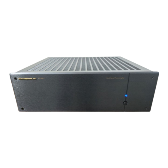
- Page 1 B&K IMPLY ETTER B&K Components, Ltd. AV125.7 & AV125.5 Owner’s Manual P/N13440 1102...
- Page 2 B&K Components, Ltd., 2100 Old Union Road, Buffalo New York 14227-2725 Phone 1-800-543-5252 or (716) 656-0026, Fax (716) 656-1291 E-mail: info@bkcomp.com Web: www.bkcomp.com...
-
Page 3: Table Of Contents
TABLE OF CONTENTS Table of Contents ..............................iii Safety Precautions ..............................1 Purpose and Function............................. 2 Design and Construction ............................2 Features..................................2 Rear Panel ................................3 Level Adjustment..............................4 Inputs ..................................4 XLR Balanced ............................... 4 RCA Unbalanced..............................4 Balanced or Unbalanced Connections........................5 Outputs .................................. -
Page 4: Safety Precautions
SAFETY PRECAUTIONS PLEASE READ BEFORE INSTALLING WARNING: to prevent fire or shock hazard, do not expose this unit to rain or moisture. Care should be taken to prevent objects or liquid from entering the enclosure. Never handle the power cord with wet hands. -
Page 5: Purpose And Function
PURPOSE AND FUNCTION The AV125.7 and AV125.5 are high power amplifiers designed for use in all types of audio or audio/video systems. DESIGN AND CONSTRUCTION The AV125.7 and AV125.5 utilize high quality electronic circuitry to achieve an environment wherein a detailed, transparent, and highly musical sound can be realized. -
Page 6: Rear Panel
REAR PANEL C O N T R O L I / O CONTROL IN ALLOWS AMPLIFIER OPERATION WHEN A 5-24V SIGNAL IS APPLIED WITH A 3.5mm MINI JACK I N P U T 1 I N P U T 2 I N P U T 3 I N P U T 4 I N P U T 5... -
Page 7: Level Adjustment
LEVEL ADJUSTMENT Generally in a home theater application, volume level is controlled by the A/V surround processor. In a system for use with the AV125.7 or AV125.5, adjustment of the volume level must performed using the external preamplifier/processor. INPUTS The AV125.7 and AV125.5 allow signal patch cables (interconnects) to be sourced from either balanced or unbalanced line level preamplifier/processor outputs. -
Page 8: Balanced Or Unbalanced Connections
BALANCED OR UNBALANCED CONNECTIONS Shown below are typical preamplifier to amplifier connections: C O N T R O L I / O CONTROL IN ALLOWS AMPLIFIER OPERATION WHEN A 5-24V SIGNAL IS APPLIED WITH A 3.5mm MINI JACK I N P U T 1 I N P U T 2 I N P U T 3 I N P U T 4... -
Page 9: Outputs
OUTPUTS Five way binding posts are provided. There is one pair provided for each channel. They are designed to accept a banana-type plug, spade-lug connector (shown below), terminal posts, and bare wire, and they are color coded for easy identification. The positive (+) post should always be connected to the speakers (+) jack. The negative (-) post should always be connected to the speakers (-) jack. -
Page 10: System Installation
SYSTEM INSTALLATION There will most likely be a number of cables involved in the installation of your home entertainment system. Preplanning is essential in order to maximize system efficiency. We recommend the following as a means of helping you reach that goal. Make a diagram of your proposed system by laying out the relative location of each component in the system. -
Page 11: Control Input And Output
CONTROL INPUT AND OUTPUT A control (trigger) system is provided on both the AV125.7 and AV125.5 amplifiers to allow remote switching of the amplifier’s standby on/off feature. The control input is designed to operate with a source (trigger) of 5-24 volts AC or DC. -
Page 12: Troubleshooting
TROUBLESHOOTING PROBLEM POSSIBLE CAUSE POSSIBLE SOLUTION No sound (‘on’ LED 1. Power cord not plugged in. 1. Reconnect power cord. not illuminated) 2. Power off at AC source. 2. Check AC switch or fuse 3. AC power inlet fuse blown or faulty 3. -
Page 13: Specifications
SPECIFICATIONS Power Rating: 8 ohms 125 watts @ 1 kHz 4 ohms 185 watts @ 1 kHz THD (S+N) 0.09 % @ 1 kHz Frequency response 5 Hz – 45 kHz Input sensitivity 0.77 Volts Input impedance 33.2 k ohms Damping factor Current (peak to peak) 16 Amps... -
Page 14: Limited Warranty
LIMITED WARRANTY B & K Components Ltd., referred to herein as B & K, warrants your B & K equipment against all defects in material and workmanship for a period of five years from the date of purchase. This warranty applies only to the original purchaser and only to equipment in normal residential use and service. -
Page 15: Rear Panel Enlarged Veiw
REAR PANEL ENLARGED VEIW... -
Page 16: Www.bkcomp.com
WWW.BKCOMP.COM B&K Components, Ltd. 2100 Old Union Road Buffalo, New York 14227 Phone: 716 – 656 - 0026...
Need help?
Do you have a question about the AV125.5 and is the answer not in the manual?
Questions and answers