Table of Contents
Advertisement
Quick Links
Advertisement
Table of Contents

Related Manuals for American Megatrends Atlas III PCI


Summary of Contents for American Megatrends Atlas III PCI
- Page 1 Atlas PCI-III Pentium ISA Motherboard User's Guide MAN-757 10/16/98...
- Page 2 Limited Warranty Buyer agrees if this product proves to be defective, that American Megatrends, Inc. is only obligated to replace or refund the purchase price of this product at American Megatrends’ discretion according to the terms and conditions on the motherboard warranty card. American Megatrends shall not be liable in tort or contract for any loss or damage, direct, incidental or consequential.
-
Page 3: Table Of Contents
Table of Contents 1 HARDWARE INSTALLATION..............1 Atlas PCI-III Dimensions ......................5 Installation Steps ........................6 Atlas PCI-III Motherboard Layout ...................7 Step 1 Unpack the Motherboard....................8 Set Jumpers ..........................9 Avoid Static Electricity......................9 Step 2 Configure CPU ......................10 Step 3 Install Memory ......................15 Step 4 Install the Motherboard....................19 Step 5 Attach Cables ......................20 Step 6 Onboard I/O........................27... -
Page 4: Technical Support
If you need help installing, configuring, or running this product, call American Megatrends technical support at 770-246-8645. You can send questions to technical support at: support@ami.com. Web Site We invite you to access the American Megatrends world wide web site at: http://www.ami.com. Atlas PCI-III PCI Pentium ISA Motherboard User’s Guide... -
Page 5: Packing List
Packing List You should have received the following: an Atlas PCI-III Pentium ISA motherboard, two serial cables, one parallel cable, a Warranty Card, and the Atlas PCI-III Pentium ISA Motherboard User's Guide. You may also purchase an optional USB cable and mounting bracket. Warning The pinout for the optional USB Cable Box is: Pin 1... -
Page 7: Hardware Installation
Hardware Installation Overview The American Megatrends Atlas PCI-III Pentium ISA motherboard includes the following features. The motherboard supports an AMD® K6 or Intel® Pentium® P54C or P55C CPU operating at 75, 90, 100, 120, 133, 150, 166, 180, 200 MHz or higher. - Page 8 Overview, Continued DRAM Cached If 256 KB of L2 secondary cache memory is installed on the motherboard, up to 128 MB of system memory can be cached. If 512 KB of L2 secondary cache memory is installed on the motherboard, up to 256 MB of system memory can be cached.
- Page 9 Overview, Continued AMIBIOS Features AMIBIOS features include: IDE block mode support, IDE 32-bit data transfer support, IDE Programmed I/O mode 0, 1, 2, 3, and 4 support, IDE LBA mode support, APM (Advanced Power Management) and Flash BIOS hooks, EPA Green PC-compliant, PCI and Plug and Play (PnP) support, and DIM (Device Initialization Manager) support, DMI (Desktop Management Interface) support,...
- Page 10 Overview, Continued Mouse The Atlas PCI-III motherboard includes both an optional miniDIN PS/2 mouse connector and a 10-pin berg mouse connector. The Atlas PCI-III motherboard has two 4-pin USB connectors. USB allows future generations of USB-compliant peripheral devices to be automatically detected and configured through a single port.
-
Page 11: Atlas Pci-Iii Dimensions
Overview, Continued PCI Slots The motherboard conforms to the PCI Version 2.1 specification. The PCI slots are automatically configured by the AMIBIOS. The PCI slots operate synchronously with the CPU clock, as follows: CPU External Clock Frequency PCI Expansion Slot Frequency 66 MHz 33 MHz 60 MHz... -
Page 12: Installation Steps
Installation Steps Step Action Turn to Unpack the motherboard. Page 8 Configure the CPU. Page 10 Select the CPU voltage. Page 11 Select the CPU speed. Page 10 Install the CPU. Page 12 Install memory. Page 15 Install the motherboard. Page 19 Attach cables to connectors. -
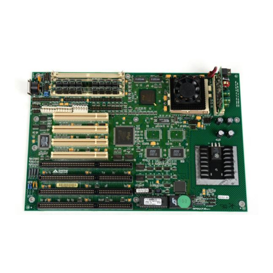
Page 13: Atlas Pci-Iii Motherboard Layout
Atlas PCI-III Motherboard Layout Chapter 1 Hardware Installation... -
Page 14: Step 1 Unpack The Motherboard
Step 1 Unpack the Motherboard Step Action Inspect the cardboard carton for obvious damage. If damaged, call 770-246-8645. Leave the motherboard in its original packing. Perform all unpacking and installation procedures on a ground- connected anti-static mat. Wear an anti-static wristband grounded at the same point as the anti-static mat. -
Page 15: Set Jumpers
Set Jumpers Set all jumpers and install the CPU before placing the motherboard in the chassis. Set jumpers by placing a shunt (shorting bridge) on the designated pins of the jumper. A shunt and jumpers are shown below: 3-dimensional view of motherboard jumpers and a shunt. Shunt 2-pin Berg 3-pin Berg... -
Page 16: Step 2 Configure Cpu
OPEN Important Please contact American Megatrends technical support at 770-246- 8645 if you need to support a CPU running at a higher speed. PCI Bus Clock J15 is a 3-pin berg that specifies the PCI bus clock speed. Short Pins 1-2 for a 66 (33) MHz CPUCLK. - Page 17 Step 2 Configure CPU, Continued J14 Set CPU Voltage Install Intel Pentium P54C, P55C, or AMD K6 CPUs that adhere to either the standard or VRE voltage specifications. J14 is a 2-pin berg that sets the CPU voltage. VRM Status J14 Setting Intel P54C NO VRM...
- Page 18 Step 2 Configure CPU, Continued Important If you are not sure about the voltage specification for the CPU that will be installed in this motherboard, please call Intel and make sure that you set the voltage jumpers correctly. Selecting the wrong voltage may damage the CPU.
- Page 19 Step 2 Configure CPU, Continued Install CPU Install the CPU in the ZIF (zero insertion force) socket by performing the following steps. The CPU socket is near one edge of the motherboard, as shown on page 7. Warning Improper CPU installation can damage the CPU and the motherboard.
- Page 20 Step 2 Configure CPU, Continued Step Action Lift the lever on the ZIF socket. The empty CPU socket looks like this. Check for bent pins on the CPU. Gently straighten any bent pins with pliers. Place the CPU in the middle of the socket. Make sure that pin 1 of the CPU is aligned with pin 1 of the socket.
-
Page 21: Step 3 Install Memory
Step 3 Install Memory System Memory The motherboard has four 32-bit SIMM – Single Inline Memory Module) sockets. You can use Fast Page Mode or EDO (Extended Data Out) SIMMs. Memory must be populated one bank at a time. Each bank has two sockets. Each bank must be populated with the same type of SIMM. - Page 22 Step 3 Install Memory, Continued DRAM Configurations Valid memory configurations include: Total RAM Bank0 Bank0 Bank1 Bank1 8 MB 4 MB 4 MB None None 16 MB 8 MB 8 MB None None 24 MB 8 MB 8 MB 4 MB 4 MB 32 MB 8 MB...
- Page 23 Step 3 Install Memory, Continued Installing SIMMs The motherboard has four x 36 SIMM sockets. These sockets can be filled with either 1 MB x 36, 4 MB x 36, 8 MB x 36, or 16 MB x 36 SIMMs. Place the motherboard on an anti-static mat.
- Page 24 Step 3 Install Memory, Continued Configure Cache Memory The motherboard supports 256 KB or 512 KB of L2 3V Pipeline Burst SRAM secondary cache memory. J9, J10, J11, and J12 are 3-pin bergs that specify the cache memory size. These jumpers are next to the CPU socket.
-
Page 25: Step 4 Install The Motherboard
Step 4 Install the Motherboard The motherboard mounting hole pattern is the same as the mounting hole pattern on the standard baby AT motherboard. Standoffs and mounting screws are not supplied with the motherboard. The chassis manufacturer should supply these parts. Step Action Place the chassis on an anti-static mat. -
Page 26: Step 5 Attach Cables
Step 5 Attach Cables Connectors The Atlas PCI-III motherboard connectors are: Connector Turn to J18 Clear password page 21 J19 IRQ12 Use page 23 P7 and P6 Power supply connectors page 21 Keyboard connector page 22 Mouse connectors page 23 J13 CPU Fan page 24 USB1 and USB2 USB connectors... - Page 27 Step 5 Attach Cables, Continued J18 Clear Password If you forget the computer password, the only course of action is to erase the system configuration information stored in the NVRAM (Non-Volatile Random Access Memory). The computer password is stored in the system configuration data.
- Page 28 Step 5 Attach Cables, Continued Connector Keys The keys on the connector must be cut to fit on some power supplies, as shown below. P6 Power Connector Pinout Description Ground (Black wire) Ground (Black wire) -5 Volts (White wire) VCC (Red wire) VCC (Red wire) VCC (Red wire) P7 Power Connector Pinout...
- Page 29 Ground Keyboard clock 10-Pin Mouse Connector Attach the mouse connector cable supplied by American Megatrends to the 10-pin mouse berg connector on the motherboard, as shown below. Attach the standard 9-pin mouse connector at the other end of the mouse cable to the mouse connector port on the computer case.
- Page 30 Step 5 Attach Cables, Continued When attaching connectors to the motherboard, make sure to connect the correct connector end. Most connector wires are color-coded. Match the color of the wires leaving the switch or LED to the same pin on the connector end. There may be more than one connector with the same color-coded wires.
- Page 31 Step 5 Attach Cables, Continued PS/2 Mouse IRQ J19 is a three-pin berg that enables the PS/2 mouse interrupt (IRQ12). Short Pins 2-3 of J19 to enable IRQ12 as the PS/2 mouse interrupt. You should always short Pins 2-3 to enable the PS/2 mouse interrupt. The only reason you would ever have to short Pins 1-2 is if you wanted an adapter card on the ISA bus to use IRQ12.
- Page 32 Step 5 Attach Cables, Continued J24 Keyboard Lock J24 is a 5-pin single-inline berg that is attached via a cable to the keyboard lock connector (or separate keyboard lock and Power LED connectors). The computer chassis may not include the keyboard lock and Power LED on a single connector.
-
Page 33: Step 6 Onboard I/O
Step 6 Onboard I/O Onboard I/O The Atlas PCI-III motherboard has: two serial ports (P1 and P2), a parallel port (P4), an IDE controller on the PCI bus. The primary IDE connector is P5. The secondary connector is P9. a floppy controller (P3). The serial and parallel port connectors are described below. - Page 34 Step 6 Onboard I/O, Continued Parallel Port P4 is a 26-pin connector for a parallel port. The LPT pinout is shown below. Connect the 26-pin to DB25 cable provided with the motherboard to P4. All parallel port settings can be configured through Peripheral Setup in WINBIOS Setup.
-
Page 35: Step 7 Attach Floppy Drive
Step 7 Attach Floppy Drive P3 is a 34-pin dual-inline berg. Connect the cable from the floppy drive to FDD, as shown below. The onboard floppy controller cannot be used if a hard disk card with a floppy controller is installed. Choose Standard Setup and Peripheral Setup to configure the floppy controller. - Page 36 Step 7 Attach Floppy Drive, Continued Floppy Connector Pinout Signal Description Signal Description DENSE1 DRATE0 -INDEX -MOTOR0 -FDSEL1 -FDSEL0 -MOTOR1 -WDATA -WGATE -TRK0 -WRPROT -RDATA HDSEL DSKCHNG Twist in Floppy Cable Floppy B to A Floppy B to A Floppy B to A Floppy B to A 10 to 16 12 to 14...
-
Page 37: Step 8 Attach Ide Drive
Step 8 Attach IDE Drive IDE Drives Attach the IDE drives in the following manner. Choose Peripheral Setup in WINBIOS Setup to enable the onboard IDE controller. Cont’d Chapter 1 Hardware Installation... - Page 38 Step 8 Attach IDE Drive, Continued Attach IDE Cable P5 is the primary IDE (Integrated Drive Electronics) hard disk drive connector. Both the primary master and the primary slave IDE drives must be connected by cable to P5, as shown below. P5 is a 40-pin dual-inline berg that connects an IDE drive to the primary onboard IDE connector.
- Page 39 Step 8 Attach IDE Drive, Continued P5 Pinout The P5 pinout is: Signal Description Signal Description -RESET DATA7 DATA8 DATA6 DATA9 DATA5 DATA10 DATA4 DATA11 DATA3 DATA12 DATA2 DATA13 DATA1 DATA14 DATA0 DATA15 KEY (N/C) -IOW -IOR IDERDY INT14 -IOCS16 -CS0 -CS1 -IDEACT...
- Page 40 Step 8 Attach IDE Drive, Continued P9 Pinout The P9 pinout is: Signal Description Signal Description -RESET DATA7 DATA8 DATA6 DATA9 DATA5 DATA10 DATA4 DATA11 DATA3 DATA12 DATA2 DATA13 DATA1 DATA14 DATA0 DATA15 KEY (N/C) -IOW -IOR IDERDY INT15 -IOCS16 -CS2 -CS3 Atlas PCI-III PCI Pentium ISA Motherboard User’s Guide...
-
Page 41: Step 9 Test And Configure
Step 9 Test and Configure Review the following points before powering up: make sure that all adapter cards are seated properly, make sure all connectors are properly installed, make sure the CPU is seated properly, make sure there are no screws or other foreign material on the motherboard, plug the system into a surge-protected power strip, and make sure blank back panels are installed on the back of the chassis to... - Page 42 Atlas PCI-III PCI Pentium ISA Motherboard User’s Guide...
-
Page 43: Winbios Setup
Historically, BIOS Setup utilities have been character-based, required keyboard input, and have had user interfaces that were not very intuitive. Graphical Interface American Megatrends has a new type of system BIOS Setup utility. WINBIOS Setup has a graphical user interface the end user can access using a mouse. -
Page 44: Using A Mouse With Winbios Setup
Using a Mouse with WINBIOS Setup WINBIOS Setup has a built-in mouse driver and can be accessed by either a serial mouse or PS/2-style mouse. WINBIOS Setup supports Microsoft- Compatible serial mice and all PS/2-type mice. The mouse click functions are: single click to change or select both global and current fields and double click to perform an operation in the selected field. -
Page 45: Winbios Setup Menu
WINBIOS Setup Menu The WINBIOS Setup main menu is organized into four sections. Each of these sections corresponds to a section in this chapter. Each section contains several icons. Clicking on each icon activates a specific AMIBIOS function. The WINBIOS Setup main windows and related functions are described on the next page. -
Page 46: Section 1 Setup
Section 1 Setup Standard Setup Standard Setup options are displayed by choosing the Standard icon from the WINBIOS Setup main menu. All Standard Setup options are described in this section. Date/Time Select the Standard option. Select the Date and Time icon. The current values for each category are displayed. - Page 47 Standard Setup, Continued Primary Master, Primary Slave, Secondary Master, Secondary Slave Select one of these hard disk drive icons to configure the hard disk drive named in the option. Select Auto from the drive parameters screen to let AMIBIOS automatically configure the drive.
- Page 48 Standard Setup, Continued Entering Drive Parameters You can also enter the hard disk drive parameters. The drive parameters are: Parameter Description Type The number for a drive with certain identification parameters. Cylinders The number of cylinders in the disk drive. Heads The number of heads.
-
Page 49: Hard Disk Drive Types
Standard Setup, Continued Hard Disk Drive Types Type Cylinders Heads Write Landing Sectors Capacity Precompensation Zone 10 MB 20 MB 31 MB 62 MB 47 MB 65535 20 MB 31 MB 65535 30 MB 65535 112 MB 65535 20 MB 65535 35 MB 65535... -
Page 50: Advanced Setup
Advanced Setup Advanced Setup options are displayed by choosing the Advanced icon from the WINBIOS Setup main menu. All Advanced Setup options are described in this section. System Keyboard This option does not specify if a keyboard is attached to the computer. Rather, it specifies if error messages are displayed if a keyboard is not attached. - Page 51 Advanced Setup, Continued Boot Up Num Lock Set this option to On to turn the Num Lock key On at system boot. The settings are On or Off. The Optimal and Fail-Safe default settings are On. Password Check This option enables the password check option every time the system boots or the end user runs Setup.
- Page 52 Advanced Setup, Continued External Cache Set this option to Enabled to enable L2 secondary (external) cache memory. The settings are Enabled or Disabled. The Optimal default setting is Enabled. The Fail-Safe default setting is Disabled. Caching Controller Set this option to Yes if a cache controller is installed in the computer. Setting Description To comply with the PCI specifications, PCI adapter cards...
- Page 53 Advanced Setup, Continued Shadow C800,16K Shadow CC00,16K Shadow D000,16K Shadow D400,16K Shadow D800,16K Shadow DC00,16K These options enable shadowing of the contents of the ROM area in the option title. Setting Description Shadow The contents of the ROM area are written to the corresponding address in RAM for faster execution.
-
Page 54: Chipset Setup
Chipset Setup Memory Hole This option allows the end user to specify a memory hole. The settings are Disabled, 512-640K, or 15-16M (from 15 MB to 16 MB). The Optimal and Fail-Safe default settings are Disabled. IRQ12/M Mouse Function This option should be set according to the mouse hardware implementation. -
Page 55: Power Management Setup
Power Management Setup The AMIBIOS Setup options described in this section are selected by choosing the Power Management Setup icon from the Setup section on the AMIBIOS Setup main menu. Power Management/APM Set this option to Enabled to enable the Intel Triton 2 power management features and APM (Advanced Power Management). - Page 56 Power Management Setup, Continued Hard Disk Power Down Mode This option specifies the power conserving state that the hard disk drive enters after the specified period of hard drive inactivity has expired. The settings are Disabled, Standby, or Suspend. The Optimal and Fail-Safe default settings are Disabled.
- Page 57 Power Management Setup, Continued Slow Clock Ratio This option specifies the speed at which the system clock runs in power saving states. The settings are expressed as a ratio between the normal CPU clock speed and the CPU clock speed when the computer is in the power- conserving state.
- Page 58 Power Management Setup, Continued IRQ3 IRQ4 IRQ5 IRQ7 IRQ9 IRQ10 IRQ11 IRQ12 IRQ13 IRQ14 IRQ15 When set to Monitor, these options enable event monitoring on the specified IRQ line. If set to Monitor and the computer is in a power saving state, AMIBIOS watches for activity on the specified IRQ line.
-
Page 59: Pci/Pnp Setup
PCI/PnP Setup Choose the PCI/PnP Setup icon from the WINBIOS Setup screen to display the PCI and Plug and Play Setup options, described below. Plug and Play-Aware OS Set this option to Yes if the operating system in this computer is aware of and follows the Plug and Play specification. - Page 60 PCI/PnP Setup, Continued PCI Slot-1 IRQ Preference PCI Slot-2 IRQ Preference PCI Slot-3 IRQ Preference PCI Slot-4 IRQ Preference These options specify the IRQ priority for PCI devices installed in the four PCI expansion slots. The settings are Auto, IRQ5, IRQ9, IRQ10, IRQ11, IRQ 14, and IRQ15, in priority order.
- Page 61 PCI/PnP Setup, Continued IRQ3 IRQ4 IRQ5 IRQ7 IRQ9 IRQ10 IRQ11 IRQ12 IRQ14 IRQ15 These options specify the bus that the specified IRQ line is used on. These options allow you to reserve IRQs for legacy ISA adapter cards. These options determine if AMIBIOS should remove an IRQ from the pool of available IRQs passed to devices that are configurable by the system BIOS.
- Page 62 PCI/PnP Setup, Continued DMA Channel 0 DMA Channel 1 DMA Channel 3 DMA Channel 5 DMA Channel 6 DMA Channel 7 These options allow you to specify the bus type used by each DMA channel. The settings are PnP or ISA. The Optimal and Fail-Safe default settings are PnP.
-
Page 63: Peripheral Setup
Peripheral Setup Choose the Peripheral Setup icon from the WINBIOS Setup screen to display the Peripheral Setup options, described below. Onboard Floppy Controller Set this option to Enabled to enable the floppy drive controller on the motherboard. The settings are Auto (AMIBIOS automatically determines if the floppy controller should be enabled), Enabled, or Disabled. - Page 64 Peripheral Setup, Continued Offboard PCI/ISA IDE Card This option specifies if an offboard PCI IDE controller adapter card is installed in the computer. You must choose ISA if an ISA IDE card is installed or the PCI expansion slot on the motherboard where the offboard PCI IDE controller is installed.
- Page 65 Peripheral Setup, Continued Serial Port1 Address This option specifies the base I/O port address of serial port 1. The settings are Auto (AMIBIOS automatically determines the correct base I/O port address), Disabled, 3F8h, or 3E8h. The Optimal default setting is 3F8h. The Fail-Safe default setting is Disabled.
- Page 66 Peripheral Setup, Continued Parallel Port Mode This option specifies the parallel port mode. The Optimal default setting is Normal. The Fail-Safe default setting is Disabled. The settings are: Setting Description The normal parallel port mode is used. Normal Use this setting to support bidirectional transfers on the Bi-Dir parallel port.
-
Page 67: Section 2 Security
Section 2 Security Three icons appear in this part of the WINBIOS Setup screen: Supervisor (Password), User (Password), and Anti-Virus (see page 63). Two Levels of Passwords Both the Supervisor and the User icons configure password support. If you use both, the Supervisor password must be set first. The system can be configured so that all users must enter a password every time the system boots or when WINBIOS Setup is executed, using either or both the Supervisor password or User password. -
Page 68: Setting A Password
Setting a Password The password check option is enabled in Advanced Setup (see the Advanced Setup section ) by choosing either Always (the password prompt appears every time the system is powered on) or Setup (the password prompt appears only when WINBIOS is run). -
Page 69: Changing A Password
Changing a Password Select the Supervisor or User icon from the Security section of the WINBIOS Setup main menu. Enter the password and press <Enter>. The screen does not display the characters entered. After the new password is entered, retype the new password as prompted and press <Enter>. -
Page 70: Section 3 Utility
Section 3 Utility The following icons appear in this section of the WINBIOS Setup main screen: Color Set Color Set sets the Setup screen colors. Language If this feature is enabled, you can select WINBIOS Setup messages in different languages. Section 4 Default The icons in this section permit you to select a group of settings for all WINBIOS Setup options. -
Page 71: Programming The Flash Rom
BIOS. The advantage of Flash EPROM is the EPROM chip does not have to be replaced to update the BIOS. The end user can actually reprogram the BIOS, using a ROM file supplied by American Megatrends. Programming the Flash EPROM... - Page 72 S757P.ROM S757P.ROM resides on a floppy disk and contains the updated main BIOS code. American Megatrends will provide this file when the AMIBIOS for the Atlas PCI-III ISA motherboard must be updated. S757P.ROM must be present in the root directory of the floppy disk before the onboard Flash EPROM can be reprogrammed.
- Page 73 Programming the Flash ROM, Continued Beep Codes The bootblock code produces a series of beeps during Flash ROM programming signify completion of a step (as shown on the previous page), or to signal an error. Error beeps are arranged in a coded sequence and have different meanings depending on when they occur.
-
Page 74: Bootblock Code Checkpoint Codes
Bootblock Code Checkpoint Codes Code Description Verify the bootblock BIOS checksum. Disable the internal cache, DMA, and interrupt controllers. Initialize the system timer. Start memory refresh. Initialize the chipset registers. Set the BIOS size to 128K. Make the 512 KB base memory available. Test the base 64 KB of system memory. -
Page 75: A Specifications
Specifications Item Description AMD K6 or Intel Pentium P54C or P55C 75, 90, 100, 120, 133, 150, 166, 180, 200 MHz or higher speed Chipset Intel 82430HX, including CPU interface controller, advanced cache controller, integrated DRAM controller, synchronous ISA bus controller, PCI local bus interface, and integrated power management unit. - Page 76 Item Description Power supply Includes three power supply connectors. Real time clock/ A real time clock and 128 bytes of CMOS RAM with a CMOS RAM battery backup is provided on the motherboard. Power Power management services include: management Green PC LED, power management signal to Green PC-aware power supplies, automatic IDE and video power down,...
-
Page 77: Index
Index 32-bit data transfer support, 69 Desktop Management Interface, 69 Device Initialization Manager, 69 DIM, 69 Display Activity, 51 DMA Channel 0, 56 Advanced Setup, 44 DMA Channel 1, 56 Allocate IRQ to PCI VGA, 53 DMA Channel 3, 56 AMIBIOS features, 69 DMA Channel 5, 56 AMIFlash... - Page 78 IDE drive Configuring, 41 Offboard PCI IDE Primary IRQ, 58 IDE Drive connectors, 31 IDE Hard Disk Connector, 32 Offboard PCI IDE Secondary IRQ, 58 Offboard PCI/ISA IDE Card, 58 Install Memory, 15 Offboard Primary/Secondary, 58 Installation, 6 Onboard Adapters, 27 Installing Adapter Cards, 35 Onboard Floppy Controller, 57 Installing the Motherboard, 19...
- Page 79 USB, 69 USB Device IRQ Preference, 53 Real time clock/, 70 USB Device Latency Timer, 53 Refresh, 14 USB Function Enable, 48 Reporting Memory, 15 USB Keyboard/Mouse Legacy Support, 48 Reserved ISA Card Memory Address, 56 User Password, 61 Reserved ISA Card Memory Size, 56 Reset Switch Connector, 25 Resource conflicts, 27 Video Power Down Mode, 49...
- Page 80 Index...
Need help?
Do you have a question about the Atlas III PCI and is the answer not in the manual?
Questions and answers