Table of Contents
Advertisement
Available languages
Available languages
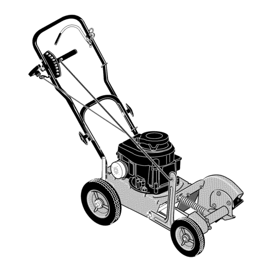
Operator's
Manual
Edger
500 Series Engine
9 Inch Blade
Model
536.772360
CAUTION:
Before using this
product,
read this manual and
follow all of its Safety Rules and
Operating
Instructions.
-IcR"FTS"""°l
-
Manual del usario
(pagina 43)
Orilladora
500 Series Engine
de 9 pulgada lamina
Modelo
536.772360
PRECAUCION:
Antes de usar este
producto,
lea este manual y siga todas
las reglas de seguridad
e instrucciones
de operaci6n.
Sears, Roebuck
and Co., Hoffman
Estates,
IL 60179 U.S.A.
1740549
www, sears,com/craftsman
TP 899-4502-01
-
EG-C
Advertisement
Table of Contents

Related Manuals for Craftsman 77236100N - 5.0 Ft-Lbs Gross Torque Edger


Summary of Contents for Craftsman 77236100N - 5.0 Ft-Lbs Gross Torque Edger
- Page 1 9 pulgada lamina Modelo 536.772360 PRECAUCION: Antes de usar este producto, lea este manual y siga todas las reglas de seguridad e instrucciones de operaci6n. Sears, Roebuck and Co., Hoffman Estates, IL 60179 U.S.A. 1740549 www, sears,com/craftsman TP 899-4502-01 EG-C...
-
Page 2: Table Of Contents
When assembled, operated and maintained according to all supplied instructions, if this Craftsman Edger fails due to a defect in material or workmanship within two years from the date of purchase, return it to any Sears store, Sears Parts & Repair Center, or other Craftsman outlet in the United States for free repair (or replacement if repair proves impossible). -
Page 3: Operator Safety
This manual contains safety WITH THIS PRODUCT: information to make you aware of the hazards and risks associated with edgers, and how to avoid them. The edger is designed and intended only for lawn care edging and trimming, and should not be used for Read Fire Manual... - Page 4 WARNING WARNING • If there is natural or LP gas leakage in area, do When Adding Fuel not start engine. • Stop the engine. Let engine cool at least 2 • Do not use pressurized starting fluids because minutes before removing the gas cap. vapors are flammable.
- Page 5 WARNING ,WARNING • Operate equipment with guards in place. • Keep hands and feet away from rotating parts. • Tie up long hair and remove jewelry. • Do not wear loose-fitting clothing, dangling Before performing adjustments or repairs: drawstrings or items that could become •...
-
Page 6: Operator Safety Rules
Operator Safety Rules • Never operate the product without guards, plates or other protective devices in place. Operate product from position where guards block the line Before Use of sight to the cutting member. • Never allow children to operate the Edger. Keep •... - Page 7 • If fuelspills,waituntilit evaporates before starting • Do not operate product with a damaged or engine. excessively worn cutting member. • Takeallpossible precautions whenleaving the • Have repairs made by a qualified dealer or Edger u nattended o rduringtransport.Stopthe repairman. See that only identical replacement engine.
-
Page 8: Assembly
Parts Packed Separately In Carton 1 - Control Rod _--- /u I! 1 - Owner's Manual (not shown) 1 - Container Of Oil 2 - Hair Pin 2 - Hair Pin 1 - Container of Oil 1 - Control ..:;:i, ii_il;;i;:i, ii_il;;i;:i, ii_il;;i;:i, ii_il;;i;:i,... -
Page 9: How To Raise The Handle
Push down on the handle to tilt the unit back. How To Raise The Handle Insert the other end of the control rod, from RIGHT 1 Loosen the knobs (A) and raise the upper handle to LEFT, through the hole in the depth control lever (B) to the upright position. -
Page 10: Features
J Blade A Engine StopLever- Mustbeengaged t o allowtheengine tostartandrun,Release K Blade Guide to stoptheengine, L Quill A ssembly B Starter R ope Handle - Theengine is IV1OilDrainPlug(located o n bottom of equipped withaneasypullrecoil s tarter. engine) C BladeDepth Lever- Controls depthofcut, N Engine Model N umber D Control R od O Product M odel N umber... -
Page 11: Operation
Eye Protection Read "Operator Safety Rules" section prior to using Always wear safety glasses. If you wear eye glasses, put a Wide Vision Safety Mask over your eye glasses. this product. Before Starting The Engine WARNING CAUTION This engine was shipped from the factory without oil. - Page 12 Gasoline Requirements All gasoline is not the same. If a starting or High-altitude performance problem is encountered after new At higher altitudes (over 5,000 feet), 85 octane / 85 gasoline has been used, try another service station or AKI (89 RON) gasoline can be used. Operation at change brands.
-
Page 13: Howto Start The Engine
How To Start The Engine Push the primer button (A) three times. Wait approximately two seconds between each push, See Figure 9, WARNING IMPORTANT: Do not use the primer button to start a warm engine. • Start and run engine outdoors. •... -
Page 14: How To Stop
How To Stop Emergency Stopping Release the engine stop lever (A). See Figure 10. Normal Stopping Move the depth control lever (B) forward to raise the blade. Then, release the engine stop lever (A) (see Figure 10). Figure 10: Operating Controls How To Use The Depth Control Lever WARNING... - Page 15 How To Use The Index Lever The cutting angle of the blade is controlled by the The three bevel cutting positions cut a trench at an index lever (A). The index lever has four cutting angle and reduce the need to edge as often. positions, one vertical cut and three bevel cut position.
- Page 16 How To Operate The Edger The edger is designed to cut a small trench along Start the engine. See "How To Start The Engine". sidewalks and driveways or to trim close to trees, Move the depth control lever back to lower the flower beds, lampposts, etc.
- Page 17 Curb-hop feature 1 Stoptheengine. N ever a djust t hewheels whilethe WARNING engine is running. 2 Setthe indexleveratvertical c utposition to prevent b ladecontact w iththecurb.Themaximum height o fa curbshould notexceed 8 inches. 3 Setthe entireedger onthecurb. 4 Inthecorrect p osition, boththerightrearwheel(A) andthefrontwheel(B)areofftothesideofthe •...
-
Page 18: Edging Tips
Edging Tips • Edging is best performed when conditions are dry. WARNING If the soil is too wet, dirt becomes packed around the blade causing premature belt wear and decreased performance. If dirt does become packed around the blade, stop the engine and remove the wire from the spark plug. -
Page 19: Maintenance
In dusty conditions, clean every 25 hours. In dusty conditions or when airborne debris is present, clean more often. Replace air cleaner if it is very dirty. *** Change oil after first 5 to 8 hours of use, then every 50 hours. -
Page 20: How To Remove The Belt
How To Remove The Belt The belt is made of a special compound. If the belt becomes worn or breaks, replace the belt with an original equipment belt. 1 Disconnect the spark plug wire from the spark plug. 2 Tilt the machine backwards on the handle. Secure the top of the handle under a bench or against a wall, 3 Remove the screws (A) from the belt guard (B) -
Page 21: How To Replace The Blade
How To Replace The Blade The blade is subject to wear and damage, such as NOTE: To remove or tighten the blade Iocknut, nicks and dents, This is normal and does not affect its always use the method shown in NO TAG. function. -
Page 22: Engine Maintenance
Engine Maintenance Carburetor Adjustment CAUTION All the components used to build this engine must Never make unnecessary adjustments to the remain in place for the proper operation of this carburetor. The carburetor was set at the factory to engine. operate efficiently under most applications. However, if adjustments are required, see any Sears or other Emission Control... - Page 23 How To Change The Oil Change oil after first 5 to 8 hours of use, then 8 To add oil, pour the oil slowly into the engine oil fill. every 50 hours. Change oil every 25 hours when The engine holds approximately 20 ounces (0.6 operating the engine under heavy load or in high liter) of oil.
- Page 24 How To Service The Air Filter Replace the air filter every 50 hours; more often in WARNING dusty or dirty conditions, CAUTION Do not use pressurized air or solvents to clean the filter. Pressurized air can damage the filter and solvents will dissolve the filter.
-
Page 25: Storage
Storage Fuel stabilizer Follow these guidelines when storing the edger for longer than 30 days. • If you do not want to remove the gasoline, add a fuel stabilizer to any gasoline left in the fuel tank. A Edger fuel stabilizer will minimize gum deposits and acids. If the fuel tank is almost empty, mix the fuel •... -
Page 26: Troubleshooting
PROBLEM CAUSE CORRECTION Stale fueJ Drain fuel tank. Fill with fresh fuel. Engine difficult to start Engine runs erratically Dirt in fuel tank or out of fue Drain and clean fuel tank. Fill with fresh i uel. Engine will not run at full speed Carburetor out of adjustment Contact a Sears or other qualified... -
Page 27: Product Specifications
Product Model No.: 536.772360 Gross Torque: 5:00 ft Ibsl Displacement: 9.67 cu. in. (158.6 cc) i quart Oil Capacity: 20 oz. SAE-30W spark Plug Gap: 0.030 inch (&76 mm) Bore 2-9/16 in. (65.09 mm) Stroke !-7/8 in; (47;63 mm) Engine Power Rating Information The gross power rating for individual gas engine operating the equipment, the gas engine will not... - Page 28 The California Air Resources Board (CARB), U.S. EPA and listed below, provided there has been no abuse, neglect or im- Sears are pleased to explain the Emissions Control System proper maintenance of your small off-road engine. Warranty on your small off-road engine (SORE). In California, Your emissions control system...
- Page 29 Look For Relevant Emission Durability Period and Air Index Information On¥our Engine Emission Label Engines that are certified to meet the California Air Resources Board (CARB) Tier 2 Emission Standards must display informa- tion regarding the Emissions Durability Period and the Air Index. Briggs &...
-
Page 30: Illustrated Parts List
CRAFTSMAN 536.772360 REPAIR PARTS EDGER BLADE ASSEMBLY Description Part Description Part Engine 500 Series 740296MA Blade, Edger 10T5020121 46023MA Nut, 1/2-20 0025x6MA Screw 338682MA Deflector, Rubber 52052MA Pulley, V3L 337792E701MA Plate, Rubber Flap 338490MA Key, Hi Pro #505 336631MA Belt Guard... - Page 31 REPAIR PARTS CRAFTSMAN 536.772360 WHEEL ASSEMBLY 21 _.. > Part Description Description Part Flat washer 120393MA 071294MA Knob, Wing Screw 180091 MA 015x68MA Locknut, Flange 0020x3MA Spring Washer 45222MA Spacer, Sleeve 845MA Washer 740091 MA Rod, Axle Front 336545MA Tire & Rim...
- Page 32 REPAIR PARTS CRAFTSMAN 536.772360 HANDLE ASSEMBLY Description Part Description Part 740142E701 Upper Handle 138485MA Washer 782585MA Nut, 1/4-20 315288MA Bolt, 5/16-18x.75 339489MA Cap, Operator Control 1498MA Nut, 5/16-18 314276MA Nut, Push On 1701051E701MA Lower Handle 337744MA 711558MA Bolt, 5/16-18x.75 Bail, Operator Control...
-
Page 34: Engine
BRIGGS & STRATTON ENGINE REPAIR PARTS MODEL 10T502-0121-E1 1058 OWNER'S MANUAL] 358 ENGINE GASKET SET [ 1330 REPAIR MANUAL 12 _ 163 _) 20 @ 524 0 200_ 51 @ 1095 VALVE GASKET SET 668 @ 524 O 718[_ _71 I o35_ _... - Page 35 BRIGGS & STRATTON ENGINE REPAIR PARTS MODEL 10T502-0121-E1 PART PART PART DESCRIPTION DESCRIPTION DESCRIPTION 699653 691111 Screw Cylinder Asembly 690959 Pin-Locating 399269 691146 Screw Kit- Bushing/Seal (Intake Manifold) 271139s Gasket-Air Cleaner (Magneto Side) (Brake) 299819 Seal-Oil 691912 Blade-Governor 691870 SeaI-O Ring 690400 (Magneto...
- Page 36 BRIGGS & STRATTON ENGINE REPAIR PARTS MODEL 10T502-0121-E1 24 [_ 741 _/_ 15 @...
- Page 37 BRIGGS & STRATTON ENGINE REPAIR PARTS MODEL 10T502-0121-E1 PART PART PART DESCRIPTION DESCRIPTION DESCRIPTION 296676 Valve-Exhaust 792532 Piston Assembly 698691 Sump-Engine 692218 Gasket-Crankcase 296677 Valve-intake (,020" Oversize) 790909 Ring Set 691680 Plug-Oil Drain 690520 Spring-Valve 692989 Crankshaft (Standard) (Intake) 3914838 Seal-Oil 690520 Spring-Valve...
- Page 38 BRIGGS & STRATTON ENGINE REPAIR PARTS MODEL 10T502-0121-E1 366 '_ 190A 42o_ 678_...
- Page 39 BRIGGS & STRATTON ENGINE REPAIR PARTS MODEL 10T502-0121-E1 PART PART PART DESCRIPTION DESCRIPTION DESCRIPTION 698369 Filter-Air Cleaner Foam 222698s Key-Flywheel 691859 Spring-Governed Idle 699660 Carburetor 691446 Bracket-Control 698472 Cleaner-Air 691931 Shaft-Throttle 496914 Armature-Magneto 697582 Wire Assembly 691901 Seat-Inlet 691061 Screw 496046s Tube-Pick 691190...
- Page 40 BRIGGS & STRATTON ENGINE REPAIR PARTS MODEL 10T502-0121-E1 1036 EMISSIONS LABEL 1329 REPLACEMENT ENGINE I 48 SHORT BLOCK 1211 1210 689 O 456 _ 613_...
- Page 41 BRIGGS & STRATTON ENGINE REPAIR PARTS MODEL 10T502-0121-E1 PART PART PART DESCRIPTION DESCRIPTION DESCRIPTION 690843 Flywheel (Blower Housing) 1210 499901 Pulley/Spring Assembly 690482 690662 Guard-Flywheel (Pulley) 691209 Guard-Flywheel (Flywheel) 1211 499901 Pulley/Spring Asembly Short Block 398213 19069 Puller-Flywheel (Spring) 692144 Housing-Rewind Starter 691236...
- Page 43 DE GARANTJA TOTAL DE LA BORDEADORA CRAFTSMAN Si la bordeadora Craftsman se ensambla, maneja y mantiene de acuerdo con todas las instrucciones suministradas, y esta falla a causa de un defecto en el material o en la mano de obra dentro para dos afios de la fecha de compra, Ilevela a cualquier tienda de...
- Page 44 SiMBOLOS ASOCIADOS Este manual contiene informaci6n de CON ESTE PRODUCTO: seguridad para alertarlo sobre los peligros y riesgos asociados con las bordeadoras, y para indicarle c6mo evitarlos. La bordeadora esta diser_ada L_nicamente para recortar y rebordear el c6sped, y no debe ser utilizada para Leer el Fuego manual...
- Page 45 ,ADVERTENCIA ADVERTENCIA Cuando cargue combustible • Si existe una fuga de gas natural o gas licuado • Detenga el motor. Deje que el motor se enfrie petr61eo en el Area, no arranque el motor. menos durante 2 minutos antes de quitar la tapa de •...
- Page 46 ADVERTENCIA ADVERTENCIA • Opere el equipo con las protecciones en su lugar. ajustes o reparaciones: • Mantenga las manos y los pies alejados de las Antes de realizar partes giratorias. • Desconecte el cable de la bujia y mant6ngalo • AmArrese el cabello, si Io tiene...
- Page 47 Normas de seguridad para el operador Seguridad operativa • Lea y siga cuidadosamente todas las instrucciones este manual. Antes de usar • Nunca opere el producto sin las protecciones, placas otros dispositivos de seguridad en su lugar. Opere • LEA Y SIGA TODAS LAS INSTRUCCIONES: producto desde...
- Page 48 • AsegOrese deque labujia est@ desconectada cuando No opere el producto con una pieza cortadora da_ada retire elmaterial atascado delapieza cortadora. No excesivamente gastada. encienda elmotor siseretir6 labujia. Solicite a un concesionario o t@cnico calificado • Sisederrama combustible, espere h asta que seevapore realice las reparaciones.
- Page 49 Las piezas estan embaladas en carton 1 - Varilla de control por separado 1 - Manual del propietario (no se muestra) 1 - Recipiente de aceite 2 - Pin de retenci6n 2 - Pin de retencion 1 - Recipiente de aceite 1 - Varilla de control Instrucciones para desembalar...
- Page 50 C6mo levantar la manija Empuje la manija hacia abajo para inclinar la unidad hacia atr_,s. Afloje las perillas (A) y levante la manija superior (B) a Introduzca el otro extremo de la varilla de control, su posici6n vertical. Ver Figura 2. DERECHA a IZQUIERDA, a trav_s...
- Page 51 A Palanca deparada d el m otor: Debe estar Cuchilla enganchada para permitir que elmotor arranque y Guia de la cuchilla semantenga enfuncionamiento. Su61tela para Conjunto de eje hueco apagar elmotor. Tap6n de drenaje de aceite (ubicado en la parte B Manija delacuerda dearranque: Elmotor est&...
- Page 52 Protecci6n para los ojos Lea la secci6n "Normas de seguridad de operaci6n" antes Siempre use gafas de protecci6n. Si usted usa anteojos, p6ngase una m_tscara de protecci6n encima de @stos. de usar este producto. ADVERTENCIA Antes de arrancar el motor PRECAUCleN Este motor se despacha de f@,brica sin aceite.
- Page 53 Requisitos de gasolina No cualquier gasolina es igual. Si detecta un problema Aprovisionamiento de combustible arranque o de rendimiento luego de usar una gasolina Apague el motor. Antes de retirar la tapa de gasolina (A), nueva, pruebe con otra estaci6n de servicio o cambie deje que el motor se enfrie...
- Page 54 Como arrancar el motor Presione el bot6n cebador (A) tres veces. Espere aproximadamente dos segundos cada vez que presione el bot6n. Ver Figura ADVERTENCIA IMPORTANTE: No use el boton cebador para arrancar un motor caliente. Arranque el motor y op6relo en exteriores, No arranque el motor...
- Page 55 Como apagar el motor Parada de emergencia Suelte la palanca de parada del motor (A). Ver Figura 10. Parada normal Mueva la palanca de control de profundidad (B) hacia adelante para levantar la cuchila. Luego, suelte la palanca de parada del motor (A) (ver Figura 10).
- Page 56 C6mo utilizar la palanca guia Ponga la palanca de control de profundidad en la altura El angulo de corte de la cuchilla se controla per medio de la palanca guia (A). La palanca guia tiene cuatro posiciones deseada. Consulte "C6mo utilizar la palanca de control de corte, un corte vertical y tres posiciones...
- Page 57 Como manejar la bordeadora La bordeadora esta dise_ada para cortar pequehas zanjas Arranque el motor. Consulte "C6mo arrancar el motor". a Io largo de las aceras y los caminos para ingreso vehiculos o para recortar alrededor de _,rboles, macizo Mueva la palanca de control de profundidad...
- Page 58 Bordeado de aceras Detenga el motor. Nunca ajuste las ruedas con el motor Utilice la palanca de control de profundidad (D) para en funcionamiento. bajar la rueda delantera hasta que haga contacto con la calzada y la bordeadora quede nivelada. Coloque la palanca guia en la posici6n...
- Page 59 Consejos de corte • El corte se realiza mejor cuando la superficie ADVERTENCIA encuentra seca. Si la tierra est,, demasiado hOmeda, cuchilla se Ilena de suciedad provocando un desgaste premature de la correa y una reducci6n en el rendimiento. • Si la cuchilla se Ilena de suciedad, apague...
- Page 60 A las Antes Cada Cada Antes del primeras Cada ,00 o,moseno PROCEDIMIENTO de cada horas horas miento horas horas iiilii Lubrique t0d0s !0S punt0s de! eje Central Lubrique los ejes de las ruedas Controle la co[rea de transmisi6n Ajuste todos los sujetadores Revise ta cuchilla para comprobar si ester desgastada o dar_ada Controle el aceite...
- Page 61 Como retirar la correa La correa ester hecha de un material especial. Si la correa se desgasta o se rompe, reempl&cela con un repuesto original. Desconecte el cable de la bujia. Incline la maquina hacia atr&s utilizando la manija. Sujete la parte superior de la manija contra...
- Page 62 Como reemplazar la cuchilla La cuchilla sufre desgastes y dar_os, come hendeduras NOTA: Para retirar o ajustar la contratuerca de la abolladuras. Generalmente 6stas no afectan cuchilla, use siempre el metodo que se muestra en funcionamiento. Figura 16. Primero, coloque la Ilave (C) para sujetar la tuerca ubicada detras de la cuchilla.
- Page 63 Mantenimiento del motor Ajuste del carburador PRECAUCION Todos los componentes utilizados para construir este motor deben mantenerse en su lugar para el Nunca realice ajustes innecesarios en el carburador. funcionamiento correcto de este motor. carburador ha sido calibrado en la f@,brica para funcionar manera 6ptima en la mayoria...
- Page 64 Como cambiar el aceite Vierta lentamente el aceite en la boca de Ilenado Cambie aceite despues de las primeras 5 a 8 horas de uso, y luego cada 50 horas. Cambie aceite cada 25 horas aceite del motor. El motor tiene capacidad para cuando...
- Page 65 C6mo mantener el filtro de aire Cambie el filtro de aire cada 50 horas de operaci6n; con ADVERTENCIA mayor frecuencia en condiciones de mucho polvo o suciedad. PRECAUCION No use aire a presi6n ni solventes para limpiar el filtro. El aire a presi6n puede dahar el filtro y los solventes...
- Page 66 Almacenamiento Estabilizador de combustible Siga estas pautas para almacenar la bordeadora durante periodo mayor a 30 dias. • Si no desea extraer la gasolina, agregue un estabilizador de combustible a la gasolina que quede en el tanque. Bordeadora estabilizador de combustible minimizar_t los dep6sitos resina y los @,cidos.
- Page 67 SOLUCION PROBLEMA CAUSA Drene el tanQue de combustible: I]enelo con Combustible viejo El motor arranca con dificultad combustible fresco. El motor marcha de forma irregular _uciedad en el tanque de Drene y limpie el tanque de combustible. _ombustible o falta de combustible Lt6nelo con combustible fresco.
- Page 68 Desplazamiento: 158,6 cc (9,67pulgadas c Qbicas) Capacidad del tanque de aceite: 20,6 litre (20 onzas) SAE-30W "ntrehierro de la bujia: 0,76 mm (0,030 pulgadas) Diametro interno: 65,09 mm (2-9/16 pulgadas) Entrehierro del inducido: 0,15-0,25 mm (0,006-0,010 pulgadas) Cuchilla: 2219 cm(9 puigadas) cuales se ubican los motores y la variedad de Informacion de potencia...
- Page 69 La Junta de Recursos Ambientales (CARB), la Agencia de Protecci6n Sears debe garantizar el sistema de control de emisiones en su motor Ambiental de los Estados Unidos (U.S. EPA) y Sears se comptacen en por los perlodos de tiempo listados abajo, teniendo en cuenta que no explicartes la Garant[a det Sistema de Control de Emisiones de su mo- haya habido abuso, negtigencia o mantenimiento no apropiado de su tor peque_ho para todo terreno (SORE).
- Page 70 Busque el Periodo de Durabilidad de Emisiones y la Informacion del Indice de Aire Pertinentes en su Etiqueta de Emisiones del Motor Los motores que son certificados porque cumplen con las Normas de Emisiones Etapa 2 de la Junta de Recursos Ambientales California (CARB)
- Page 72 Your Home ........ppli ........For repair-in your home-of all ma or brand a ances, ........lawn and garden equ ment, or heating and cooling systems, ........no matter who made it, no matter who sold it! ........For the re acement parts, a_ssories ........
Need help?
Do you have a question about the 77236100N - 5.0 Ft-Lbs Gross Torque Edger and is the answer not in the manual?
Questions and answers