HP dx7500 - Microtower PC Hardware Reference Manual
Microtower model business pc
Hide thumbs
Also See for dx7500 - Microtower PC:
- Service & reference manual (200 pages) ,
- Hardware reference manual (59 pages) ,
- Troubleshooting manual (53 pages)
Table of Contents
Advertisement
Quick Links
Advertisement
Table of Contents

Related Manuals for HP dx7500 - Microtower PC


Summary of Contents for HP dx7500 - Microtower PC
- Page 1 Hardware Reference Guide - dx7500 Microtower Model HP Compaq Business PC...
- Page 2 No part of this document may be photocopied, reproduced, or translated to another language without the prior written consent of Hewlett-Packard Company. Hardware Reference Guide HP Compaq Business PC dx7500 Microtower Model First Edition (August 2008) Document Part Number: 498187-001...
-
Page 3: About This Book
About This Book This guide provides basic information for upgrading this computer model. WARNING! Text set off in this manner indicates that failure to follow directions could result in bodily harm or loss of life. CAUTION: Text set off in this manner indicates that failure to follow directions could result in damage to equipment or loss of information. - Page 4 About This Book ENWW...
-
Page 5: Table Of Contents
Table of contents 1 Product Features Standard Configuration Features ......................1 Serviceability Features ......................... 1 Front Panel Components ........................2 Media Card Reader Components ......................3 Rear Panel Components ........................4 Keyboard .............................. 5 Using the Windows Logo Key ....................5 Serial Number Location ........................ - Page 6 Appendix B Battery Replacement Appendix C External Security Devices Installing a Security Lock ........................44 Cable Lock ......................... 44 Padlock ..........................45 HP Business PC Security Lock ..................45 Appendix D Electrostatic Discharge Preventing Electrostatic Damage ....................... 48 Grounding Methods ..........................48 Appendix E Computer Operating Guidelines, Routine Care and Shipping Preparation Computer Operating Guidelines and Routine Care ................
-
Page 7: Product Features
Product Features Standard Configuration Features The HP Compaq Microtower features may vary depending on the model. For a complete listing of the hardware and software installed in the computer, run the diagnostic utility (included on some computer models only). Instructions for using the utility are provided in the Troubleshooting Guide. -
Page 8: Front Panel Components
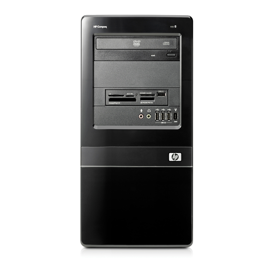
Front Panel Components Drive configuration may vary by model. Figure 1-2 Front Panel Components Table 1-1 Front Panel Components 5.25-inch Optical Drives Hard Drive Activity Light Optical Drive Activity Lights Optical Drive Eject Buttons 3.5-inch Media Card Reader (optional) Headphone Connector Microphone Connector USB (Universal Serial Bus) 2.0 Ports Dual-State Power Button... -
Page 9: Media Card Reader Components
Media Card Reader Components The media card reader is an optional device available on some models only. Refer to the following illustration and table to identify the media card reader components. Figure 1-3 Media Card Reader Components Table 1-2 Media Card Reader Components Slot Media ●... -
Page 10: Rear Panel Components
Rear Panel Components Figure 1-4 Rear Panel Components Table 1-3 Rear Panel Components Power Cord Connector PS/2 Mouse Connector (green) Voltage Select Switch Line-Out Connector for powered audio devices (green) Line-In Audio Connector (blue) Microphone Connector (pink) RJ-45 Network Connector Universal Serial Bus (USB) Ports 1394 Port DVI Monitor Connector (white) -
Page 11: Keyboard
Keyboard Figure 1-5 Keyboard Components Table 1-4 Keyboard Components Function Keys Perform special functions depending on the software application being used. Editing Keys Include the following: Insert, Home, Page Up, Delete, End, and Page Down. Status Lights Indicate the status of the computer and keyboard settings (Num Lock, Caps Lock, and Scroll Lock). - Page 12 Table 1-5 Windows Logo Key Functions (continued) Windows Logo Key + Launches Find Document Windows Logo Key + Ctrl Launches Find Computer Windows Logo Key + Launches Windows Help Windows Logo Key + Locks the computer if you are connected to a network domain, or allows you to switch users if you are not connected to a network domain Windows Logo Key +...
-
Page 13: Serial Number Location
Serial Number Location Each computer has a unique serial number and product ID number that are located on the upper left side of the computer. Keep these numbers available for use when contacting customer service for assistance. Figure 1-6 Serial Number and Product ID Location ENWW Serial Number Location... -
Page 14: Hardware Upgrades
Hardware Upgrades Warnings and Cautions Before performing upgrades be sure to carefully read all of the applicable instructions, cautions, and warnings in this guide. WARNING! To reduce the risk of personal injury from electrical shock, hot surfaces, or fire: Disconnect the power cord from the wall outlet and allow the internal system components to cool before touching. -
Page 15: Removing The Computer Access Panel
Removing the Computer Access Panel Remove/disengage any security devices that prohibit opening the computer. Remove all removable media, such as diskettes or compact discs, from the computer. Turn off the computer properly through the operating system, then turn off any external devices. Disconnect the power cord from the power outlet and disconnect any external devices. -
Page 16: Replacing The Computer Access Panel
Replacing the Computer Access Panel Place the access panel on the chassis with about 1.3 cm (1/2 inch) of the panel hanging off the back of the chassis and slide it into place (1). Ensure that the hole for the screw is aligned with the hole in the chassis and tighten the screw (2). -
Page 17: Removing The Front Bezel
Removing the Front Bezel Remove/disengage any security devices that prohibit opening the computer. Remove all removable media, such as diskettes or compact discs, from the computer. Turn off the computer properly through the operating system, then turn off any external devices. Disconnect the power cord from the power outlet and disconnect any external devices. -
Page 18: Removing Bezel Blanks
Removing Bezel Blanks On some models, there are bezel blanks covering the 3.5-inch and 5.25-inch external drive bays that need to be removed before installing a drive. To remove a bezel blank: Follow the instructions described in Removing the Front Bezel on page Press the two retaining tabs towards the outer left edge of the bezel (1) and pull the bezel blank inwards to remove it (2). -
Page 19: Replacing The Front Bezel
Replacing the Front Bezel Insert the three hooks on the left side of the bezel into the slots on the chassis (1) and rotate the bezel on from left to right (2) so that it snaps in place. Figure 2-5 Replacing the Front Bezel ENWW Replacing the Front Bezel... -
Page 20: Installing Additional Memory
Installing Additional Memory The computer comes with double data rate 2 synchronous dynamic random access memory (DDR2- SDRAM) dual inline memory modules (DIMMs). DIMMs The memory sockets on the system board can be populated with up to four industry-standard DIMMs. These memory sockets are populated with at least one preinstalled DIMM. -
Page 21: Populating Dimm Sockets
Populating DIMM Sockets There are four DIMM sockets on the system board, with two sockets per channel. The sockets are labeled DIMM1, DIMM2, DIMM3, and DIMM4. Sockets DIMM1 and DIMM2 operate in memory channel A. Sockets DIMM3 and DIMM4 operate in memory channel B. Figure 2-6 DIMM Socket Locations Table 2-1... -
Page 22: Installing Dimms
with the least amount of memory describes the total amount of memory assigned to dual channel and the remainder is assigned to single channel. For optimal speed, the channels should be balanced so that the largest amount of memory is spread between the two channels. If one channel will have more memory than the other, the larger amount should be assigned to Channel A. - Page 23 Open both latches of the memory module socket (1), and insert the memory module into the socket (2). Figure 2-7 Installing a DIMM NOTE: A memory module can be installed in only one way. Match the notch on the module with the tab on the memory socket.
-
Page 24: Removing Or Installing An Expansion Card
Removing or Installing an Expansion Card The computer has three PCI Express x1 expansion slots and one PCI Express x16 expansion slot. The expansion slots accommodate full-height or half-height expansion cards. Figure 2-8 Expansion Slot Locations Table 2-2 Expansion Slot Locations Item Description PCI Express x1 expansion slot... - Page 25 Locate the correct vacant expansion socket on the system board and the corresponding expansion slot on the back of the computer chassis. On the rear of the computer, a slot cover lock secures the expansion card brackets in place. Remove the screw from the slot cover lock then slide the slot cover lock up to remove it from the chassis.
- Page 26 NOTE: Before removing an installed expansion card, disconnect any cables that may be attached to the expansion card. If you are installing an expansion card in a vacant socket, you must use a flatblade screwdriver to pry out the metal shield on the rear panel that covers the expansion slot. Be sure to remove the appropriate shield for the expansion card you are installing.
- Page 27 If you are removing a PCI Express x16 card, pull the retention arm on the back of the expansion socket away from the card and carefully rock the card back and forth until the connectors pull free from the socket. Be sure not to scrape the card against the other components. Figure 2-12 Removing a PCI Express x16 Expansion Card Store the removed card in anti-static packaging.
- Page 28 To install a new expansion card, hold the card just above the expansion socket on the system board then move the card toward the rear of the chassis so that the bottom of the bracket on the card slides into the small slot on the chassis. Press the card straight down into the expansion socket on the system board.
-
Page 29: Drive Positions
Reconnect the power cord and any external devices, then turn on the computer. Lock any security devices that were disengaged when the access panel was removed. Reconfigure the computer, if necessary. Refer to the Computer Setup (F10) Utility Guide for instructions on using Computer Setup. -
Page 30: Installing Additional Drives
Installing Additional Drives When installing additional drives, follow these guidelines: ● The primary Serial ATA (SATA) hard drive must be connected to the dark blue primary SATA connector on the system board labeled SATA0. ● Connect the first SATA optical drive to the white SATA connector on the system board labeled SATA1. -
Page 31: System Board Drive Connections
CAUTION: To prevent loss of work and damage to the computer or drive: If you are inserting or removing a drive, shut down the operating system properly, turn off the computer, and unplug the power cord. Do not remove a drive while the computer is on or in standby mode. Before handling a drive, ensure that you are discharged of static electricity. -
Page 32: Removing An Optical Drive
Table 2-3 System Board Drive Connections (continued) System Board Connector System Board Label Color SATA0 SATA0 dark blue Diskette Drive FLOPPY black Removing an Optical Drive CAUTION: All removable media should be taken out of a drive before removing the drive from the computer. -
Page 33: Installing An Optical Drive Into The 5.25-Inch Drive Bay
Remove the two screws that secure the drive to the drive cage (1), then slide the drive out of the front of the chassis (2). Figure 2-19 Removing the Optical Drive NOTE: To install an optical drive, refer to Installing an Optical Drive into the 5.25-inch Drive Bay on page Installing an Optical Drive into the 5.25-inch Drive Bay To install an optional 5.25-inch optical drive:... - Page 34 Slide the drive in through the front of the chassis (1) until the screw holes on the drive are aligned with the screw holes on the drive cage and install the two M3 metric retainer screws (2) as shown in the following illustration. NOTE: Extra drive retainer screws are provided on the interior of the front bezel if needed.
-
Page 35: Removing An External 3.5-Inch Drive
The system automatically recognizes the drive and reconfigures the computer. Removing an External 3.5-inch Drive CAUTION: All removable media should be taken out of a drive before removing the drive from the computer. NOTE: The 3.5-inch drive bay may contain a diskette drive or a media card reader. Remove/disengage any security devices that prohibit opening the computer. - Page 36 If you are removing a media card reader, disconnect the USB cable from the system board. Figure 2-23 Disconnecting the Media Card Reader Cable Remove the two retainer screws that secure the drive to the bay (1) then slide the drive forward and out of the bay (2).
-
Page 37: Installing A Drive Into The 3.5-Inch External Drive Bay
Installing a Drive into the 3.5-inch External Drive Bay The 3.5-inch external drive bay on the front of the computer can be configured with a media card reader or a diskette drive. Remove/disengage any security devices that prohibit opening the computer. Remove all removable media, such as diskettes or compact discs, from the computer. -
Page 38: Removing An Internal 3.5-Inch Hard Drive
Connect the appropriate drive cables: If installing a diskette drive, connect the power and data cables to the rear of the drive and connect the other end of the data cable to the connector on the system board labeled FLOPPY. If installing a media card reader, connect the USB cable from the media card reader to the USB connector on the system board labeled F_USB2. - Page 39 Remove the two screws that secure the hard drive cage to the chassis. Figure 2-26 Removing the Hard Drive Cage Screws Push down the latch on the side of the hard drive cage (1), then slide the hard drive cage away from the bottom of the chassis (2) as shown below.
- Page 40 Lift the hard drive cage out of the chassis. Figure 2-28 Removing the Hard Drive Cage Disconnect the power cable (1) and data cable (2) from the back of the hard drive. Figure 2-29 Disconnecting the Hard Drive Cables Chapter 2 Hardware Upgrades ENWW...
-
Page 41: Installing An Internal 3.5-Inch Hard Drive
Remove the four screws that secure the hard disk drive to the hard drive cage (1), then slide the hard disk drive out of the hard drive cage (2). Figure 2-30 Removing the Hard Drive NOTE: To install an internal 3.5-inch hard drive, refer to Installing an Internal 3.5-inch Hard Drive on page Installing an Internal 3.5-inch Hard Drive... - Page 42 Slide the new drive into the hard drive cage (1), aligning the drive with the four screw holes on the cage. Install the four 6-32 standard screws that secure the hard disk drive to the hard drive cage (2). Make sure the hard disk drive cables are facing the top of the drive cage. NOTE: If you are replacing an old drive with a new drive, use the four retainer screws from the old drive to install the new drive.
- Page 43 Connect the power cable (1) and data cable (2) to the back of the hard drive. Figure 2-32 Connecting the Hard Drive Cables CAUTION: Never crease or bend a SATA data cable tighter than a 30 mm (1.18 in) radius. A sharp bend can break the internal wires.
- Page 44 Attach the two screws that secure the hard drive cage to the chassis. Figure 2-34 Securing the Hard Drive Cage If installing a new drive, connect the opposite end of the data cable to the appropriate system board connector. NOTE: If your system has only one SATA hard drive, you must connect the hard drive data cable to the dark blue connector labeled SATA0 to avoid any hard drive performance problems.
-
Page 45: Appendix A Specifications
Specifications Table A-1 Specifications Desktop Dimensions 14.76 in 37.5 cm Height 6.98 in 17.73 cm Width 16.88 in 42.87 cm Depth Approximate Weight 23.5 lb 10.66 kg Temperature Range 50° to 95°F 10° to 35°C Operating -22° to 140°F -30° to 60°C Nonoperating Relative Humidity (noncondensing) 10-90%... - Page 46 Table A-1 Specifications (continued) Rated Input Current (maximum) 8A @ 100 VAC 4A @ 200 VAC This system utilizes a passive power factor corrected power supply. The power factor correction is present in the 230V operating mode only. This allows the system to pass the CE mark requirements for use in the countries of the European Union. This supply requires the use of an input voltage range select switch.
-
Page 47: Battery Replacement
Battery Replacement The battery that comes with the computer provides power to the real-time clock. When replacing the battery, use a battery equivalent to the battery originally installed in the computer. The computer comes with a 3-volt lithium coin cell battery. WARNING! The computer contains an internal lithium manganese dioxide battery. - Page 48 NOTE: On some computer models, it may be necessary to remove an internal component to gain access to the battery. Depending on the type of battery holder on the system board, complete the following instructions to replace the battery. Type 1 Lift the battery out of its holder.
- Page 49 Insert the new battery and position the clip back into place. Figure B-3 Removing a Coin Cell Battery (Type 3) NOTE: After the battery has been replaced, use the following steps to complete this procedure. Replace the computer access panel. Plug in the computer and turn on power to the computer.
-
Page 50: Appendix C External Security Devices
External Security Devices NOTE: For information on data security features, refer to the Computer Setup (F10) Utility Guide and the Desktop Management Guide. Installing a Security Lock The security locks displayed below and on the following pages can be used to secure the computer. Cable Lock Figure C-1 Installing a Cable Lock... -
Page 51: Padlock
Padlock Figure C-2 Installing a Padlock HP Business PC Security Lock Fasten the security cable by looping it around a stationary object. Figure C-3 Securing the Cable to a Fixed Object ENWW Installing a Security Lock... - Page 52 Thread the keyboard and mouse cables through the lock. Figure C-4 Threading the Keyboard and Mouse Cables Screw the lock to the chassis using the screw provided. Figure C-5 Attaching the Lock to the Chassis Appendix C External Security Devices ENWW...
- Page 53 Insert the plug end of the security cable into the lock (1) and push the button in (2) to engage the lock. Use the key provided to disengage the lock. Figure C-6 Engaging the Lock ENWW Installing a Security Lock...
-
Page 54: Appendix D Electrostatic Discharge
Electrostatic Discharge A discharge of static electricity from a finger or other conductor may damage system boards or other static-sensitive devices. This type of damage may reduce the life expectancy of the device. Preventing Electrostatic Damage To prevent electrostatic damage, observe the following precautions: ●... -
Page 55: Appendix E Computer Operating Guidelines, Routine Care And Shipping Preparation
Computer Operating Guidelines, Routine Care and Shipping Preparation Computer Operating Guidelines and Routine Care Follow these guidelines to properly set up and care for the computer and monitor: ● Keep the computer away from excessive moisture, direct sunlight, and extremes of heat and cold. ●... -
Page 56: Optical Drive Precautions
Optical Drive Precautions Be sure to observe the following guidelines while operating or cleaning the optical drive. Operation ● Do not move the drive during operation. This may cause it to malfunction during reading. ● Avoid exposing the drive to sudden changes in temperature, as condensation may form inside the unit. -
Page 57: Index
Index Symbols/Numerics expansion slot cover locks 1394 port 2, 4 removing 20 cable lock 44 replacing 21 HP Business PC Security Lock 45 access panel padlock 45 locking and unlocking 44 front bezel removing 9 removing 11 replacing 10 removing blanks 12 media card reader audio connectors 2, 4 replacing 13... - Page 58 bezel blanks 12 computer access panel 9 diskette drive 29 expansion card 18 expansion slot cover 20 front bezel 11 hard drive 32 media card reader 29 optical drive 26 PCI Express x1 card 20 PCI Express x16 card 21 security cable lock 44 HP Business PC Security...
Need help?
Do you have a question about the dx7500 - Microtower PC and is the answer not in the manual?
Questions and answers