LaCie 12big Rack Serial User Manual
Sas enclosure
Hide thumbs
Also See for 12big Rack Serial:
- User manual (87 pages) ,
- Technical brief (54 pages) ,
- Quick install manual (13 pages)
Table of Contents
Advertisement
Quick Links
Download this manual
See also:
User Manual
LaCie 12big Rack Serial
User Manual
Table of Contents
1. System Overview ......................................................................................................... 6
1.1. LaCie 12big Rack Serial SAS Enclosure ........................................................................................... 6
1.2. The Enclosure Core Product ........................................................................................................... 7
1.2.1. The Enclosure As Supplied ................................................................................................. 7
1.2.2. Drive Carrier Modules....................................................................................................... 7
1.2.3. Cables............................................................................................................................. 8
1.2.4. StorView ® Storage Management Software ......................................................................... 8
1.3. Enclosure Components .................................................................................................................. 8
1.3.1. Enclosure Chassis ............................................................................................................. 8
1.3.2. Operator's Panel .............................................................................................................. 9
1.3.3. Alarms ............................................................................................................................. 9
1.4. The Plug-in Modules ................................................................................................................... 10
1.4.1. Dual Power Supply Operation ......................................................................................... 10
1.4.2. AC Power Supply ............................................................................................................ 11
1.4.3. Dual Fan Cooling Module............................................................................................... 11
1.4.4. I/O Module ................................................................................................................... 12
1.4.5. Drive Carrier Module ...................................................................................................... 13
1.4.6. Dummy Carrier Modules ................................................................................................. 13
1.4.7. Blank Modules ............................................................................................................... 13
2. Installation ................................................................................................................ 14
2.1. Introduction ................................................................................................................................ 14
2.2. Planning Your Installation ............................................................................................................ 14
2.2.1. Enclosure Drive Bay Numbering Convention ..................................................................... 15
2.2.2. Drive Carrier Configuration ............................................................................................. 15
2.2.3. Enclosure Expansion ....................................................................................................... 15
2.3. Enclosure Installation Pre-Requisites .............................................................................................. 16
2.3.1. Preparation of Site and Host Server .................................................................................. 16
2.3.2. Unpacking the Enclosure System ...................................................................................... 16
2.4. Installation Procedures ................................................................................................................ 17
2.4.1. Special Tools and Equipment ........................................................................................... 17
2.4.2. Rack Installation Pre-Requisites ........................................................................................ 17
2.4.3. Rack Installation Procedure.............................................................................................. 18
2.4.4. Chassis Installation ......................................................................................................... 19
2.5. Module Installation ..................................................................................................................... 20
2.5.1. Drive Slot Arrangement ................................................................................................... 20
2.5.2. Engaging the Drive Carrier Anti-tamper Locks ................................................................... 21
2.6. Power Cord Connection .............................................................................................................. 22
1.2.1.1. Product Feature Codes ........................................................................................ 7
1.3.3.1. Visible Alarms ..................................................................................................... 9
1.3.3.2. Audible Alarms ................................................................................................. 10
1.4.5.1. Drive Status Indicators ....................................................................................... 13
1.4.5.2. Anti-tamper Locks ............................................................................................. 13
2.4.2.1. Rack Mounting Rail Kit ...................................................................................... 17
2.4.3.1. Parts Checklist .................................................................................................. 18
2.4.3.2. Installation Procedure........................................................................................ 18
2.4.4.1. Parts Check List ................................................................................................ 19
2.4.4.2. Procedure ........................................................................................................ 19
2.5.1.1. Drive Spindle Start ............................................................................................ 21
2.5.2.1. Activating the Locks .......................................................................................... 21
Table of Contents
page 1
Advertisement
Table of Contents
Troubleshooting

Related Manuals for LaCie 12big Rack Serial


Summary of Contents for LaCie 12big Rack Serial
-
Page 1: Table Of Contents
User Manual page 1 Table of Contents 1. System Overview ......................6 1.1. LaCie 12big Rack Serial SAS Enclosure ................... 6 1.2. The Enclosure Core Product ......................7 1.2.1. The Enclosure As Supplied ....................7 1.2.1.1. Product Feature Codes ..................7 1.2.2. - Page 2 4.1.2. Initial Start-up Problems ....................33 4.1.2.1. Faulty Connections ................... 33 4.1.2.2. Alarm Sounds On Power Up ................33 4.1.2.3. Computer Doesn’t Recognize the LaCie 12big Rack Serial ........33 4.1.3. Faulty Modules ....................... 33 4.2. Audible Alarm ..........................33 4.2.1.
- Page 3 7.5.2. Europe & Others ......................51 7.6. EMC Precautions ........................51 7.7. ESD Precautions ......................... 51 7.8. Recycling of Waste Electrical and Electronic Equipment (WEEE) ............51 8. Contacting Customer Support ................... 52 8.1. LaCie Technical Support Contacts ....................52 9. Warranty Information ....................53...
- Page 4 Fibre Channel Arbitrated Loop (FC-AL) and SAS or SATA environments into which you are installing the LaCie 12big Rack Serial RAID and La- Cie 12big Rack Serial expansion storage solutions. If you do not have these skills,...
- Page 5 It must in the technical specification. ✦ Do not lift A LaCie 12big Rack Se- provide overcurrent protection rial by the handles on the plug-in...
-
Page 6: System Overview
1. System Overview 1.1. LaCie 12big Rack Serial SAS Enclosure The LaCie 12big Rack Serial Enclosure Platform is a 2U (rack space) disk drive enclosure, housing twelve low profile (1 inch high), 3.5 inch form factor disc drives, which can be either: ✦... -
Page 7: The Enclosure Core Product
1.2. The Enclosure Core Product 1.2.1. The Enclosure As Supplied The LaCie 12big Rack Serial design concept is based on an en- closure subsystem together with a set of plug-in modules and, as supplied, comprises: ✦ Chassis and Backplane with integral (front panel mounted) Operator’s Panel (See... -
Page 8: Cables
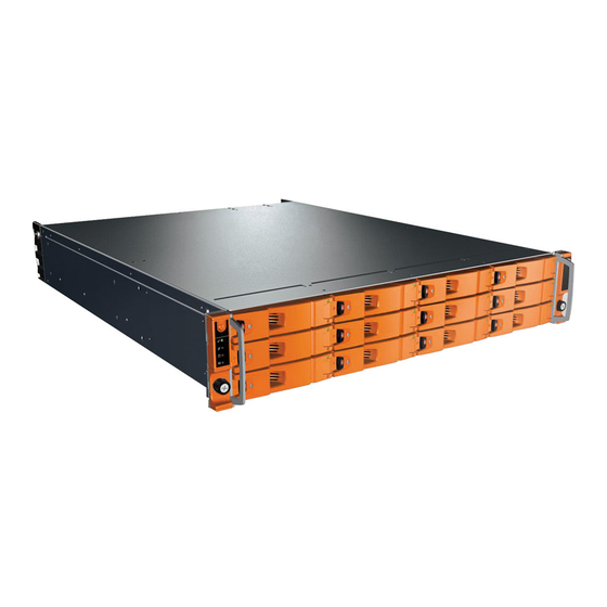
Fig. 04 - LaCie 12big Rack Serial Enclosure (Front View) A GUI application, StorView ® Storage Management software, is available on CD to aid the management of the 12big rack serial. This host pc based software is a full-featured graphical HTML-based software suite designed to configure, manage and monitor the La- Cie 12big Rack Serial Module Storage Solution. -
Page 9: Operator's Panel
User Manual page 9 1.3.2. Operator’s Panel The LaCie 12big Rack Serial front panel incorporates an Operator’s (Ops) Panel with four LEDs, see Fig. 06. The Ops Panel provides the user with a high level indication of the operation of the Enclosure. -
Page 10: Audible Alarms
1.4.1. Dual Power Supply Operation The LaCie 12big Rack Serial must always be operated with two PSUs fitted. The two Power Supply modules operate together so that if one fails the other maintains the power supply and cooling while you replace the faulty unit. -
Page 11: Ac Power Supply
LaCie 12big Rack Serial System Overview User Manual page 11 1.4.2. AC Power Supply Two 100-240VAC 350W Power Supply Units (Fig. 07) are supplied mounted in the rear of the enclosure as part of the enclosure core product. PSU voltage operating ranges are nominally 115V or 230VAC, se- lected automatically. -
Page 12: I/O Module
User Manual page 12 1.4.4. I/O Module The LaCie 12big Rack Serial storage expansion subsystems include an enclosure with rear facing bays which house two SAS I/O mod- ules, shown in Fig. The plug-in I/O modules have been designed for integration into LaCie 12big Rack Serial storage subsystems, utilizing SAS intercon- nections with the host computer system. -
Page 13: Drive Carrier Module
Fig. 14 - Blank (I/O) Module CAUTION: Operation of the Enclosure with ANY modules missing will disrupt the airflow and the drives will not receive sufficient cool- ing. It is ESSENTIAL that all apertures are filled before operating the LaCie 12big Rack Serial system. -
Page 14: Installation
User Manual page 14 2. Installation 2.1. Introduction In this chapter, you are shown how to install your LaCie 12big Rack Serial into an industry standard 19 inch rack cabinet and configure the enclosure sub-system. CAUTION: When connecting up the LaCie 12big Rack Serial, use... -
Page 15: Enclosure Drive Bay Numbering Convention
Table 02 - Enclosure System Configuration. When planning your system configuration, please remember that all LaCie 12big Rack Serial enclosure drive bays must be filled with either a Drive Carrier or Dummy Carrier module, no bays should be left completely empty. -
Page 16: Enclosure Installation Pre-Requisites
2.3.1. Preparation of Site and Host Server Before you begin, make sure that the site where you intend to set up and use your LaCie 12big Rack Serial storage system has the Fig. 16 - Unpacking the Enclosure System following: ✦... -
Page 17: Installation Procedures
There are no special tools required but in order to complete the as- sembly of some configurations you may need the following: ✦ Torx Driver, T10 tamper resistant, black (one of these should be included with your LaCie 12big Rack Serial for use with the drive locks). ✦ Standard screwdrivers and wrenches. -
Page 18: Rack Installation Procedure
LaCie 12big Rack Serial Installation User Manual page 18 2.4.3. Rack Installation Procedure Please refer to the detail drawings supplied with the rack mounting rail kit for further information 2.4.3.1. Parts Checklist Rack Mounting Rail Kit 2.4.3.2. Installation Procedure 1. Remove the Rack Mounting Kit from the Accessories Box and check for damage. -
Page 19: Chassis Installation
LaCie 12big Rack Serial Installation User Manual page 19 Assemble the rack brackets to the rack posts as follows (see Fig. 20). a. Locate the location pin at the rear of the rail into a rear rail post hole. Attach the bracket to the rear rack post using the washers and screws supplied. -
Page 20: Module Installation
1 x I/O Module in Module 0 location, see Fig. 28 and 1 x LRC Blank Assembly. (A LaCie 12big Rack Serial sys- tem can be upgraded to a LaCie 12big Rack Serial system at a future date.) ✦... -
Page 21: Drive Spindle Start
LaCie 12big Rack Serial Installation User Manual page 21 2.5.1.1. Drive Spindle Start Drive spindle start is automatically controlled via the I/O modules controlling the power control circuit of the Backplane. With two ac- tive PSUs present all drives will start immediately. If only a single PSU is present then the system will start in two groups of 6 drives, separated by a 12 second delay. -
Page 22: Power Cord Connection
LaCie 12big Rack Serial Installation User Manual page 22 2.6. Power Cord Connection Parts checklist: Power cord to requisite local standards CAUTION: Rack Installation: The enclosures should be installed SECURELY in the rack before connecting to the power supply. Dan- ger of the enclosure moving and possibly slipping out of the rack unless secured. -
Page 23: Enclosure Configurations
Installation User Manual page 23 2.7. Enclosure Configurations The basic configuration is a single LaCie 12big Rack Serial con- nected to a single Host Bus Adaptor (HBA), see Fig. Before setting up your enclosure please ensure that you have the following: ✦... -
Page 24: Grounding Checks
– Connect the LaCie 12big Rack Serial power cord to the rack distribution and the enclosure. ✦ If a direct connection is made with the LaCie 12big Rack Serial power cord, ensure that it is connected to the enclosure. CAUTION:... -
Page 25: Data Security
LaCie 12big Rack Serial Installation User Manual page 25 2.9. Data Security ✦ Power down your host computer and all attached peripheral devices before beginning installation. ✦ Each enclosure contains up to 12 removable disk drive mod- ules. Disk units are fragile. Handle them with care, and keep them away from strong magnetic fields. -
Page 26: Operation
User Manual page 26 3. Operation 3.1. Before You Begin Before powering up the LaCie 12big Rack Serial please ensure that all the modules are firmly seated in their correct bays, see Fig. CAUTION: The LaCie 12big Rack Serial must only be operated with two PSUs installed. -
Page 27: Audible Alarm
LaCie 12big Rack Serial Operation User Manual page 27 3.3. Audible Alarm Table 04 - Power Supply LEDs Power On & Module Fault Status The enclosure subsystem includes an Audible Alarm which indicates OK(Green) (Amber) when a fault state is present. Please refer to section 4.2. -
Page 28: Dual Fan Cooling Module Led
LaCie 12big Rack Serial Operation User Manual page 28 3.6.2. Dual Fan Cooling Module LED An Amber FAULT LED is incorporated in the handle of the Dual Fan Cooling Module, defined in Table 05 - Dual Fan Cooling Module LED. - Page 29 LaCie 12big Rack Serial Operation User Manual page 29 Ops Panel LEDs Other Associated State Description LEDs or Alarms Flashing PSU Module Fault Single PSU Failure LED On Intermittent beep Flashing Intermittent beep PSU Removed Flashing Intermittent beep Over or under Temperature Warning...
-
Page 30: I/O Module Leds
Flashing RQST IDENT bit set in Enclosure element. * If a LaCie 12big Rack Serial fault LED is fitted, this will be set for all the above conditions. In addition this LEd will flash for an I/O module soft failure. -
Page 31: Drive Carrier Module Leds
LaCie 12big Rack Serial Operation User Manual page 31 LED Functions Status Identifies specific module when module fault occurs. (see Table 06 - Ops Panel States) Module OK All Activity LEDs flash synchronously (1Hz) when there is a Fault con- dition. -
Page 32: Scsi Enclosure Services (Ses)
LaCie 12big Rack Serial Operation User Manual page 32 3.7. SCSI Enclosure Services (SES) SCSI Enclosure Services (SES) forms the primary route to accessing the Enclosure’s status, diagnostic and control capabilities. This information is transferred in-band over the SAS topology. The Enclosure presents a SCSI Target on the topology to which a subset of SCSI SPC commands can be directed. -
Page 33: Troubleshooting & Problem Solving
✦ Fan Fault 4.2. Audible Alarm. ✦ Voltage out of range ✦ Over temperature 4.1.2.3. Computer Doesn’t Recognize the LaCie 12big ✦ System fault Rack Serial ✦ Logical fault 1. Check that the SAS interface cables from the LaCie 12big Rack... -
Page 34: Audible Alarm Mute
LaCie 12big Rack Serial Troubleshooting & Problem Solving User Manual page 34 ✦ PSU Fault ✦ Removal of 1 PSU The alarm states are defined in Table 09 - Alarm States. 4.2.1. Audible Alarm Mute When the Audible Alarm sounds, it may be muted by pressing the Alarm Mute push-button, located on the Ops panel. -
Page 35: Troubleshooting
LaCie 12big Rack Serial Troubleshooting & Problem Solving User Manual page 35 4.3. Troubleshooting The following sections describe problems, with possible solutions, which can occur with your LaCie 12big Rack Serial Enclosure. 4.3.1. System Faults Table 10 - Troubleshooting System Faults Symptom Cause Action 1. -
Page 36: Dual Fan Cooling Module Faults
Cooling Module Flashing. 4.3.4. Thermal Control The LaCie 12big Rack Serial uses extensive thermal monitoring and take a number of actions to ensure component temperatures are kept low and also to minimize acoustic noise. Air flow is from front to rear of the enclosure. -
Page 37: Thermal Alarm
LaCie 12big Rack Serial Troubleshooting & Problem Solving User Manual page 37 4.3.5. Thermal Alarm Table 14 - Troubleshooting Thermal Alarm Symptom Cause Action 1. Ops Panel SYSTEM FAULT 1. If the internal temperature measured in the airflow 1. Check local ambient environment LED AMBER. -
Page 38: Dealing With Hardware Faults
There are two ways to perform this upgrade, one uses the diagnostic remove any module, replace it immediately. If the enclosure is used serial port on the LaCie 12big Rack Serial (Out of Band) and the with plug-in modules, Dummy Carriers or Blank modules missing... -
Page 39: Module Removal & Replacement
Please refer to chapter for information on the initial 2. Installation installation of the plug-in modules in the LaCie 12big Rack Serial enclosure. CAUTION: Observe all conventional ESD precautions when han- dling LaCie 12big Rack Serial modules and components. Avoid... -
Page 40: Power Supply Units
LaCie 12big Rack Serial Module Removal & Replacement User Manual page 40 5.4. Power Supply Units 5.4.1. Removing a Power Supply Unit CAUTION: Do not remove the faulty PSU unless you have a re- placement unit of the correct type ready for insertion. the system must not be operated without both PSUs in place. -
Page 41: Installing A Power Supply Unit
LaCie 12big Rack Serial Module Removal & Replacement User Manual page 41 5.4.2. Installing a Power Supply Unit CAUTION: Do not mix PSUs of different types or makes. 1. Check for damage, especially to the rear connector on the PSU. -
Page 42: Installing A Dual Fan Cooling Module
LaCie 12big Rack Serial Module Removal & Replacement User Manual page 42 5.5.2. Installing a Dual Fan Cooling Module 1. Check for damage, especially to the rear connector on the sup- ply. CAUTION: Handle the module carefully and avoid damaging the connector pins. -
Page 43: Installing An I/O Module
LaCie 12big Rack Serial Module Removal & Replacement User Manual page 43 5.6.2. Installing an I/O Module IMPORTANT INFO: If only one I/O module is fitted it MUST be installed in the lower (Slot 0) location (see Fig. 28), otherwise direct dock SATA will not work. -
Page 44: Drive Carrier Module
5.7.2.1. Drive Carrier Configuration IMPORTANT INFO: Before you install the Drive Carrier Modules in your LaCie 12big Rack Serial enclosure, please refer to section 2.2. Planning Your Installation for system configuration information. Fig. 42 - Removing a Drive Carrier Module (step 3) -
Page 45: Installation Procedure
LaCie 12big Rack Serial Module Removal & Replacement User Manual page 45 5.7.3. Installation Procedure IMPORTANT INFO: Ensure that the carrier is orientated so that the drive is uppermost and the handle opens from the left. 1. Ensure that the anti-tamper lock is disengaged (see Fig. -
Page 46: Dummy Carrier Module Removal/Replacement
5.8. Replacement Parts and Ancillary Items The following Field Replaceable Units (FRUs) are available for LaCie 12big Rack Serial Enclosure Platform: ✦ Chassis including Backplane, integrated Ops Panel and Dual Fan Cooling Module ✦... -
Page 47: Technical Specifications
LaCie 12big Rack Serial Technical Specifications User Manual page 47 6. Technical Specifications 6.1. Dimensions Table 16 - Technical Specifications: Dimensions Enclosure inches Height 3.46 87.9 Width across mounting flange Width across body of enclosure 17.6 Depth from flange to rear of enclosure 21.65... -
Page 48: Power Consumption
15.1A 23.0A ✦ 0.86 kg (1.91 lb.) w/750 GB drive installed Operating 5° C to 40° C (when installed in a LaCie Temperature 12big Rack Serial system enclosure with 6.5. I/O Module Specification dual Power Supply Modules) Table 20 - Technical Specifications: I/O Module Power 18.5 Watts maximum... -
Page 49: Environmental Specification
LaCie 12big Rack Serial Technical Specifications User Manual page 49 6.7. Environmental Specification Table 22 - Technical Specifications: Ambient Temperature and Humidity Temperature Range Relative Humidity Max. Wet Bulb Operational 5°C to 40°C 8% to 80% non-condensing 23°C Non-Operational 1°C to +50°C 8% to 80% non-condensing 27°C... -
Page 50: Standards & Regulations
Standards & Regulations User Manual page 50 7. Standards & Regulations 7.1. International Standards The LaCie 12big Rack Serial complies with the requirements of the following agencies and standards: ✦ CE to EN60950 ✦ IEC 60950 ✦ UL 60950-1 ✦ cUL ✦... -
Page 51: European Regulations
ESD pre- 7.5.1. United States cautions when handling LaCie 12big Rack Serial plug-in modules and components. Avoid contact with backplane components and Must be NRTL LISTED (National Recognized Test Laboratory, e.g. -
Page 52: Contacting Customer Support
LaCie 12big Rack Serial Contacting Customer Support User Manual page 52 8. Contacting Customer Support 8.1. LaCie Technical Support Contacts LaCie Asia, Singapore, and Hong Kong LaCie Australia Contact us at: Contact us at: http://www.lacie.com/asia/contact/ http://www.lacie.com/au/contact/ LaCie Belgium LaCie Canada... -
Page 53: Warranty Information
✦ The tamper seal on the drive casing is broken. LaCie and its suppliers accept no liability for any loss of data during the use of this device, or for any of the problems caused as a result. LaCie will not, under any circumstances, be liable for direct, special...
Need help?
Do you have a question about the 12big Rack Serial and is the answer not in the manual?
Questions and answers