LaCie 12big Rack Network User Manual
User manual
Hide thumbs
Also See for 12big Rack Network:
- User manual (87 pages) ,
- Technical brief (54 pages) ,
- Quick install manual (13 pages)
Table of Contents
Advertisement
Quick Links
Download this manual
See also:
User Manual
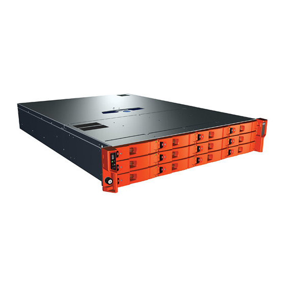
LaCie 12big Rack Network
User Manual
Table of Contents
1. System Overview ......................................................................................................... 7
1.1. The LaCie 12big Rack Network System .......................................................................................... 7
1.2. The Enclosure Core Product ........................................................................................................... 8
1.3. LaCie 12big Rack Network System Configurations .......................................................................... 9
1.4. ATX Server Subsystem .................................................................................................................. 10
1.4.1. ATX Server I/O Panel Connectors .................................................................................... 11
1.4.2. ATX Server LEDs ............................................................................................................. 11
1.5. Operator's (Ops) Panel ............................................................................................................... 12
1.6. Enclosure Rear Panel ................................................................................................................... 12
1.7. Power Supply Unit ....................................................................................................................... 13
1.7.1. Multiple Power Supply Units ............................................................................................. 13
1.7.2. Power Supply Output Loom ............................................................................................. 14
1.8. Cooling Fans .............................................................................................................................. 14
1.9. Drive Carrier Module .................................................................................................................. 15
1.9.1. Drive Status Indicator ...................................................................................................... 15
1.9.2. Anti-tamper Locks ........................................................................................................... 15
1.9.3. Dummy Drive Carrier Modules ........................................................................................ 15
1.9.4. Blanking Plates ............................................................................................................... 16
1.10. Enclosure Management ............................................................................................................... 16
2. Installation ................................................................................................................ 17
2.1. Introduction ................................................................................................................................ 17
2.2. Planning Your Installation ............................................................................................................ 17
2.3. Enclosure Installation Pre-Requisites .............................................................................................. 18
2.3.1. Preparation of Site and Host Server .................................................................................. 18
2.3.2. Unpacking the Enclosure System ...................................................................................... 18
2.3.3. Planning and Configuring Your Installation ....................................................................... 18
2.3.4. Special Tools and Equipment ........................................................................................... 19
2.3.5. Rack Installation Pre-Requisites ........................................................................................ 19
2.4. Rack Mounting Rail Kit ................................................................................................................ 19
2.4.1. Mounting Rail Kit Installation ........................................................................................... 19
2.5. Chassis Installation ..................................................................................................................... 20
2.5.1. Parts Check List .............................................................................................................. 20
2.5.2. Procedure ...................................................................................................................... 20
2.6. Module Installation ..................................................................................................................... 20
2.6.1. Dummy Drive Carrier Modules ........................................................................................ 20
2.6.2. Blanking Plates ............................................................................................................... 20
2.7. Power Cord Connection .............................................................................................................. 20
2.7.1. Parts Check List .............................................................................................................. 20
2.7.2. Procedure ...................................................................................................................... 20
2.8. Grounding Checks ...................................................................................................................... 21
2.9. Data Security .............................................................................................................................. 21
3. Operation ................................................................................................................. 22
3.1. Before You Begin ........................................................................................................................ 22
3.2. Power On .................................................................................................................................. 22
3.2.1. Power Supply Unit LEDs................................................................................................... 22
3.3. Ops Panel LEDs and Switches ...................................................................................................... 23
3.4. Starting the Drives ....................................................................................................................... 24
3.4.1. Disk Drive LEDs .............................................................................................................. 24
1.4.2.1. Status LEDs ...................................................................................................... 11
Table of Contents
page 1
Advertisement
Table of Contents
Troubleshooting

Related Manuals for LaCie 12big Rack Network


Summary of Contents for LaCie 12big Rack Network
-
Page 1: Table Of Contents
1 Table of Contents 1. System Overview ......................7 1.1. The LaCie 12big Rack Network System ..................7 1.2. The Enclosure Core Product ......................8 1.3. LaCie 12big Rack Network System Configurations ................9 1.4. ATX Server Subsystem ........................10 1.4.1. - Page 2 4.1.1. Initial Start-up Problems ....................26 4.1.1.1. Faulty Cords ....................26 4.1.1.2. Alarm Sounds On Power Up ................26 4.1.1.3. Computer Doesn’t Recognize the LaCie 12big Rack Network Subsystem ....26 4.2. LED States ..........................27 4.2.1. Power Supply Unit LEDs....................27 4.2.2.
- Page 3 7.8. Recycling of Waste Electrical and Electronic Equipment (WEEE) ............51 8. Rack Kit Reference Drawing ..................52 8.1. Rail Kit Installation ........................52 9. Contacting Customer Support ................... 54 9.1. LaCie Technical Support Contacts ....................54 10. Warranty Information ....................55...
- Page 4 LaCie 12big Rack Net- means, for any purpose, without the writ- be exposed in performing a task work storage subsystem to your host com- ten permission of the Authors.
-
Page 5: Safety Guidelines
Do not try to lift it by your- CAUTION: Bifurcated power cords self. MUST NOT be used with the LaCie 12big Rack Network enclosure, this system does CAUTION: The RJ45 sockets on the Do not lift the enclosure by the handles not support their use. - Page 6 LaCie 12big Rack Network Foreword User Manual page 6 Rack System Safety ✦ The system must be operated with from all the power supplies in all the low pressure rear exhaust installa- units. The rack will require labelling Precautions tion. (Back pressure created by rack with “HIGH LEAKAGE CURRENT.
-
Page 7: System Overview
1. System Overview 1.1. The LaCie 12big Rack Network System The LaCie 12big Rack Network storage system is a 2U (rack space) disk drive enclosure, currently housing up to twelve low profile (1 inch high), 3.5 inch form factor drives as follows: ✦... -
Page 8: The Enclosure Core Product
System Overview User Manual page 8 1.2. The Enclosure Core Product The LaCie 12big Rack Network design concept is based on an enclosure subsystem together with a set of plug-in modules and (as supplied) comprises: ✦ An Enclosure Chassis comprising: –... -
Page 9: Lacie 12Big Rack Network System Configurations
LaCie 12big Rack Network System Overview User Manual page 9 1.3. LaCie 12big Rack Network System Configurations The following LaCie 12big Rack Network system configurations are offered: Table 01 - System Configurations (Configuration A) Configuration A Basic System plus: Quad Core Intel 5420... -
Page 10: Atx Server Subsystem
LaCie 12big Rack Network System Overview User Manual page 10 The top cover on the enclosure provides access to the Cooling Fans and the ATX Server Subsystem. IMPORTANT INFO: The cover should only be removed by service personnel as it provides access to a service area. -
Page 11: Atx Server I/O Panel Connectors
LaCie 12big Rack Network System Overview User Manual page 11 1.4.1. ATX Server I/O Panel Connectors The ATX Server I/O panel incorporates the following connectors: ✦ PS2 Mouse ✦ PS2 Keyboard ✦ Serial Port ✦ Video ✦ 2 x RJ45 - NIC Ports 1 & 2 (1Gb) ✦... -
Page 12: Operator's (Ops) Panel
LaCie 12big Rack Network System Overview User Manual page 12 1.5. Operator’s (Ops) Panel The enclosure front panel incorporates an Operator’s (Ops) Panel, shown in Fig. IMPORTANT INFO: The Ops Panel is an integral part of the en- closure chassis assembly and is not field replaceable. -
Page 13: Power Supply Unit
1.7.1. Multiple Power Supply Units The LaCie 12big Rack Network includes two PSUs fitted in the Pow- er Supply Mounting Cage, providing dual power sources for the sys- tem so that if one PSU fails the other maintains the power supply and enclosure operation is not affected while you replace the faulty unit. -
Page 14: Power Supply Output Loom
LaCie 12big Rack Network System Overview User Manual page 14 1.7.2. Power Supply Output Loom The Power Supply output loom provides the following outputs: ✦ P1 ATX Motherboard main power connectors (24 pin). ✦ P2 Processor power connector (8 pin) ✦... -
Page 15: Drive Carrier Module
LaCie 12big Rack Network System Overview User Manual page 15 1.9. Drive Carrier Module The Drive Carrier module comprises a hard disk mounted in a car- rier. Each drive bay will house a single Low Profile 1.0 inch high, 3.5 inch form factor disk drive in its carrier. -
Page 16: Blanking Plates
LaCie 12big Rack Network System Overview User Manual page 16 1.9.4. Blanking Plates Blanking Plates must be fitted in any vacant PSU bay or PCI card slots at the rear of the enclosure to maintain airflow and ensure correct operation. -
Page 17: Installation
User Manual page 17 2. Installation 2.1. Introduction In this chapter, you are shown how to plan and install your LaCie 12big Rack Network Enclosure system into an industry standard 19 inch rack cabinet. CAUTION: When connecting up the LaCie 12big Rack Network... -
Page 18: Enclosure Installation Pre-Requisites
Preparation of Site and Host Server Before you begin, make sure that the site where you intend to set up and use your LaCie 12big Rack Network storage system has the following: ✦ Standard AC power from an independent source or a rack Power Distribution Unit with a UPS (universal power supply). -
Page 19: Special Tools And Equipment
✦ Torx driver (for drive module locks) 2.3.5. Rack Installation Pre-Requisites The LaCie 12big Rack Network Enclosure is designed for installa- tion into an industry standard 19 inch cabinet capable of holding the unit. ✦ Minimum depth 707mm (27.83 inches) from rack posts to maximum extremity of enclosure (excludes rear cabling). -
Page 20: Chassis Installation
CAUTION: Bifurcated power cords MUST NOT be used with the board, Enclosure Management PCB, SAS Expander PCB, Ops Pan- LaCie 12big Rack Network enclosure, this system does not support el, Intel® RAID Controller (optional), Battery Backup Unit (optional) their use. -
Page 21: Grounding Checks
LaCie 12big Rack Network Installation User Manual page 21 2.8. Grounding Checks The product must only be connected to a power source that has a safety electrical earth connection. CAUTION: If more than one product is fitted in a rack, the earth connection to the rack is even more important, because the rack will then have a high “EARTH LEAKAGE CURRENT”... -
Page 22: Operation
LaCie 12big Rack Network Operation User Manual page 22 3. Operation 3.1. Before You Begin Before powering up the enclosure please ensure that all the modules are firmly seated in their correct bays. 3.2. Power On CAUTION: Do not operate the subsystem until the ambient tem- perature is within the specified operating range. -
Page 23: Ops Panel Leds And Switches
LaCie 12big Rack Network Operation User Manual page 23 3.3. Ops Panel LEDs and Switches The Ops Panel LEDs (Fig. 15) fault and status conditions are defined Table 05 while the functions of the push-button switches are de- fined in... -
Page 24: Starting The Drives
LaCie 12big Rack Network Operation User Manual page 24 3.4. Starting the Drives Unless otherwise selected during installation, all drives in the enclo- sure should automatically start their motors. If this has not occurred one of the following conditions may exist: ✦... -
Page 25: Power Down
LaCie 12big Rack Network Operation User Manual page 25 3.5. Power Down To power the enclosure down, either ✦ Switch off the Power Supply Unit(s) installed in the enclosure by pressing the Power push-button on the Ops Panel assembly (shown in Fig. -
Page 26: Troubleshooting & Problem Solving
4.1.1.3. Computer Doesn’t Recognize the LaCie 12big Rack Network Subsystem 1. Check that the interface cables from the LaCie 12big Rack Net- work enclosure to the host computer are fitted correctly. 2. Check that the LEDs on all installed drive carrier modules are illuminated (Amber). -
Page 27: Led States
LaCie 12big Rack Network Troubleshooting & Problem Solving User Manual page 27 4.2. LED States Green LEDs are always used for good or positive indication, flash- ing Green/Amber if non-critical conditions exist. Red or Amber LEDs indicate there is a critical fault present within the module; with the... -
Page 28: Cooling Fan Leds
LaCie 12big Rack Network Troubleshooting & Problem Solving User Manual page 28 4.2.3. Cooling Fan LEDs An Amber LED incorporated in each fan module monitors its sta- tus, constant On indicates a Fault condition while a flashing light indicates that the fan ident is On. The LED is Off during Normal operation. -
Page 29: Atx Server Leds
LaCie 12big Rack Network Troubleshooting & Problem Solving User Manual page 29 4.2.6. ATX Server LEDs 4.2.6.1. Status LEDs The ATX Motherboard I/O panel contains a number of diagnostic LEDs, summarized in Table Table 10 - ATX Server Status LEDs... -
Page 30: Audible Alarm
LaCie 12big Rack Network Troubleshooting & Problem Solving User Manual page 30 4.3. Audible Alarm The PSUs include Audible Alarms which indicates when a fault state is present. A Voltage Out Of Range condition will activate the au- dible alarm: The audible alarm can be muted by pressing the Enclosure ID button on the Ops Panel. - Page 31 LaCie 12big Rack Network Troubleshooting & Problem Solving User Manual page 31 LED/Buzzer State Related Meaning Action Constant On Constant – no fan lights Failure State – tem- Check ambient tempera- lit constant perature in range where ture and increase if too...
-
Page 32: Troubleshooting
32 4.5. Troubleshooting 4.5.3. Cooling Fan Faults Table 15 - Cooling Fan Faults The following sections describe common problems, with possible solutions, which can occur with your LaCie 12big Rack Network Symptom Cause Action system. Front Panel Any power... -
Page 33: Thermal Monitoring And Control
33 4.5.4. Thermal Monitoring and Control The LaCie 12big Rack Network enclosure uses extensive thermal monitoring and takes a number of actions to ensure component temperatures are kept low and also to minimize acoustic noise. Air flow is from front to rear of the enclosure. -
Page 34: Drive Carrier Module Faults
CAUTION: If the LaCie 12big Rack Network subsystem is powered up and you remove any module, replace it immediately. If the sub- system is used with modules or module blanks missing for more than a few minutes, the enclosure can overheat, causing power failure and data loss. -
Page 35: Module Replacement
User Manual page 35 5. Module Replacement 5.1. Overview The LaCie 12big Rack Network Enclosure includes an Enclosure Services Processor and associated monitoring and control logic to enable it to diagnose problems within the enclosure’s power, cool- ing and drive systems. -
Page 36: Power Supply Units
Module Removal & Replacement User Manual page 36 5.3.1. Power Supply Units The LaCie 12big Rack Network enclosure system incorporates two PSUs, housed in a mounting cage. PSU modules are individually installed. IMPORTANT: A faulty PSU must be replaced by a fully operational PSU within 24 hours. -
Page 37: Installing A Power Supply Unit
LaCie 12big Rack Network Module Removal & Replacement User Manual page 37 5.3.1.2. Installing a Power Supply Unit CAUTION: This procedure should be performed by Service Person- nel only. Two PSUs can be installed in the mounting cage at the rear of the enclosure, see Fig. -
Page 38: Cooling Fans
User Manual page 38 5.3.2. Cooling Fans The LaCie 12big Rack Network enclosure system incorporates ten cooling fans, housed in a Cooling Cage. Fan modules are individu- ally installed. IMPORTANT INFO: A faulty Cooling Fan must be replaced by a fully operational Cooling Fan within 72 hours. -
Page 39: Installing A Cooling Fan
Drive Carrier Module CAUTION: Observe all conventional ESD precautions when handling LaCie 12big Rack Network modules and components. Avoid contact with backplane components and module connectors, etc. 5.3.3.1. Removing a Drive Carrier Drive spin down: Damage can occur to a drive if it is removed while still spinning. -
Page 40: Installing A Drive Carrier
LaCie 12big Rack Network Module Removal & Replacement User Manual page 40 5.3.3.2. Installing a Drive Carrier IMPORTANT INFO: A Drive Carrier module cannot be installed if its anti-tamper lock is activated outside the enclosure. Please refer to section 5.3.3.1. Removing a Drive Carrier for the de-activation procedure. -
Page 41: Replacing The Sas Expander Pcb
LaCie 12big Rack Network Module Removal & Replacement User Manual page 41 CAUTION: Ensure that all drive carriers are fully engaged in the enclosure by firmly pushing each one home into the slot, as shown Fig. Activating the Anti-tamper Locks 1. -
Page 42: Replacing Atx Motherboards
DIMM modules are identified and recognized by the system. 5.5.2. Replacing a CPU The LaCie 12big Rack Network enclosure system supports up to 2 Intel CPUs. It includes support for both dual and quad core proces- sor packages. 1. To access the CPU, release the enclosure top cover by turning the lock mechanism to the “unlocked “position and slide the... -
Page 43: Replacing Pci Cards
LaCie 12big Rack Network Module Removal & Replacement User Manual page 43 5.6. Replacing PCI Cards retaining bracket at the back of the enclosure, disconnect the BBU/PCM (Portable Cache Module) and SAS cables and lift the PCB upwards and out of the enclosure. - Page 44 LaCie 12big Rack Network Module Removal & Replacement User Manual page 44 To access the Battery Backup Unit: 1. Release the enclosure top cover by turning the lock mechanism to the “unlocked” position pressing the release latch down and sliding the cover back until it stops.
-
Page 45: Replacing The Boot Drives
LaCie 12big Rack Network Module Removal & Replacement User Manual page 45 5.10. Replacing the Boot Drives CAUTION: When handling drives, ensure that they are placed (and stored) on a cushioned surface. You can replace individual boot drives or the complete boot drive module. - Page 46 LaCie 12big Rack Network Module Removal & Replacement User Manual page 46 14. Relocate the module in the enclosure, securing with the three screws removed at step 5. 15. Replace the fan ducting, securing with the two screws removed at step 4.
-
Page 47: Technical Specifications
LaCie 12big Rack Network Technical Specifications User Manual page 47 6. Technical Specifications 6.1. Dimensions Rack Enclosure Inches Height 3.46 87.9 Width across mounting flange 19.01 Width across body of enclosure 17.68 Depth from rack posts to rear of PCI bulkhead 26.82... -
Page 48: Ac Power Module (2 X 850W Psu)
LaCie 12big Rack Network Technical Specifications User Manual page 48 Shock, Non-Operational 20g 10ms 1/2 sine (test w drives) 30g 10ms 1/2 sine (test w/o drives) Vibration, Operational 0.2grms 5-500 Hz Random Vibration, Non-Operational 0.8grms 2-200 Hz Random (test w drives) 1.04grms 2-200 Hz Random (test w/o drives) -
Page 49: Cooling Fan
Operated from resettable fused 12V from supply rail 6.6. Drive Carrier Module Specification IMPORTANT INFO: Operating the LaCie 12big Rack Network subsystem with non-approved drives may invalidate the warranty. Module Dimensions Height 26.6 mm Width 106.5 mm Depth 220.2 mm Weight 0.8 kg (1.0”... -
Page 50: Standards & Regulations
7. Standards & Regulations 7.1. International Standards 7.3. European Regulations The LaCie 12big Rack Network storage system complies with the This equipment complies with European Regulations EN 55022 requirements of the following agencies and standards: Class A: Limits and Methods of Measurement of Radio Distur- bance Characteristics of Information Technology Equipment and ✦... -
Page 51: Emc Compliance
LaCie 12big Rack Network Standards & Regulations User Manual page 51 7.6. EMC Compliance 7.8. Recycling of Waste Electrical and Electronic Equipment (WEEE) Conducted Emissions Limit Levels CFR47 Part 15B Class A At the end of the products life, all scrap/ waste electrical and elec-... -
Page 52: Rack Kit Reference Drawing
8.1. Rail Kit Installation Fig. 38 shows the ATX Reduced Rail Kit drawing which is included with the Rack Mounting Rail Kit and provides rail assembly details. Please contact LaCie for the latest issue of this drawing. continued on the next page >>... - Page 53 LaCie 12big Rack Network Rack Kit Reference Drawing User Manual page 53 Fig. 38 - Rail Kit Installation Drawing...
-
Page 54: Contacting Customer Support
LaCie 12big Rack Network Contacting Customer Support User Manual page 54 9. Contacting Customer Support 9.1. LaCie Technical Support Contacts LaCie Asia LaCie Australia Contact us at: Contact us at: http://www.lacie.com/asia/contact/ http://www.lacie.com/au/contact/ LaCie Belgium LaCie Canada Contact us at: Contact us at: http://www.lacie.com/be/contact/... -
Page 55: Warranty Information
✦ The tamper seal on the drive casing is broken. LaCie and its suppliers accept no liability for any loss of data during the use of this device, or for any of the problems caused as a result. LaCie will not, under any circumstances, be liable for direct, special...
Need help?
Do you have a question about the 12big Rack Network and is the answer not in the manual?
Questions and answers