Table of Contents
Advertisement
Quick Links
Advertisement
Table of Contents

Related Manuals for Asus K8N-LR


Summary of Contents for Asus K8N-LR
- Page 1 K8N-LR...
- Page 2 Product warranty or service will not be extended if: (1) the product is repaired, modified or altered, unless such repair, modification of alteration is authorized in writing by ASUS; or (2) the serial number of the product is defaced or missing.
-
Page 3: Table Of Contents
Contents Notices ....................vii Safety information ................viii About this guide .................. ix Typography ..................x K8N-LR specifications summary ............xi Chapter 1: Product introduction Welcome! ................1-1 Package contents ..............1-1 Special features ..............1-2 1.3.1 Product highlights ........... 1-2 1.3.2... - Page 4 Managing and updating your BIOS ........4-1 4.1.1 Creating a bootable floppy disk ......4-1 4.1.2 AFUDOS utility ............4-2 4.1.3 ASUS CrashFree BIOS 2 utility ........ 4-5 4.1.4 ASUS Update utility ..........4-7 BIOS setup program ............4-10 4.2.1 BIOS menu screen ..........4-11 4.2.2...
- Page 5 Contents 4.4.1 CPU Configuration ..........4-18 4.4.2 Chipset ..............4-19 4.4.3 Onboard Devices Configuration ......4-23 4.4.4 PCI PnP ..............4-25 4.4.5 MPS Configuration ..........4-26 4.4.6 USB Configuration ..........4-28 4.4.7 AMD Cool ʻNʼ Quiet Configuration ......4-29 4.4.8 Hyper Transport Configuration ......
- Page 6 Contents LAN driver installation ............6-3 Support CD information ............6-4 6.3.1 Running the support CD .......... 6-4 6.3.2 Drivers menu ............6-5 6.3.3 Management Software ..........6-6 6.3.4 Utilities ..............6-7 Appendix: Reference information K8N-LR block diagram ............A-1...
-
Page 7: Notices
Notices Federal Communications Commission Statement This device complies with Part 15 of the FCC Rules. Operation is subject to the following two conditions: • This device may not cause harmful interference, and • This device must accept any interference received including interference that may cause undesired operation. -
Page 8: Safety Information
Safety information Electrical safety • To prevent electrical shock hazard, disconnect the power cable from the electrical outlet before relocating the system. • When adding or removing devices to or from the system, ensure that the power cables for the devices are unplugged before the signal cables are connected. -
Page 9: About This Guide
Refer to the following sources for additional information and for product and software updates. ASUS websites The ASUS website provides updated information on ASUS hardware and software products. Refer to the ASUS contact information. Optional documentation Your product package may include optional documentation, such as warranty flyers, that may have been added by your dealer. -
Page 10: Typography
Conventions used in this guide To make sure that you perform certain tasks properly, take note of the following symbols used throughout this manual. DANGER/WARNING: Information to prevent injury to yourself when trying to complete a task. CAUTION: Information to prevent damage to the components when trying to complete a task. -
Page 11: K8N-Lr Specifications Summary
K8N-LR specifications summary Socket 939 for AMD Athlon™ 64 and Opteron™ 64 processors Supports AMD 64 architecture that enables simultaneous 32-bit and 64-bit computing Chipset NVIDIA nForce™ 4 SLI ® System Bus 1600/2000 MT per second Memory Dual-channel memory architecture... - Page 12 K8N-LR specifications summary 1 x Floppy disk drive connector Internal 2 x IDE connectors connectors 4 x Serial ATA connectors 2 x CPU Fan connectors 2 x Front fan connectors 2 x Rear fan connectors 1 x Mini-PCI connector (optional)
-
Page 13: Chapter 1: Product Introduction
This chapter describes the motherboard features and the new technologies it supports. Product introduction... - Page 14 Chapter summary Welcome! ................1-1 Package contents ..............1-1 Special features ..............1-2 ASUS K8N-LR...
-
Page 15: Welcome
® The motherboard delivers a host of new features and latest technologies, making it another standout in the long line of ASUS quality motherboards! Before you start installing the motherboard, and hardware devices on it, check the items in your package with the list below. -
Page 16: Special Features
Special features 1.3.1 Product highlights Latest processor and 64-bit computing technology The AMD Athlon™ 64 and AMD Opteron™ 64 desktop processors are based on AMDʼs 64-bit and 32-bit architecture, which represents the landmark introduction of the industryʼs first x86-64 technology. These processors provide a dramatic leap forward in compatibility, performance, investment protection, and reduced total cost of ownership and development. -
Page 17: Innovative Asus Features
See section “4.5.4 Hardware Monitor” on page 4-33. 1.3.2 Innovative ASUS features CrashFree BIOS 2 This feature allows you to restore the original BIOS data from the support CD in case when the BIOS codes and data are corrupted. This protection eliminates the need to buy a replacement ROM chip. - Page 18 Chapter 1: Product introduction...
-
Page 19: Chapter 2: Hardware Information
This chapter lists the hardware setup procedures that you have to perform when installing system components. It includes description of the jumpers and connectors on the motherboard. Hardware information... - Page 20 Chapter summary Before you proceed .............. 2-1 Motherboard overview ............2-2 Central Processing Unit (CPU) ..........2-6 System memory ..............2-11 Expansion slots ..............2-13 Jumpers ................2-16 Connectors ................. 2-20 ASUS K8N-LR...
-
Page 21: Before You Proceed
The CPU warning LED lights up to indicate that a processor is not installed or the processor is not installed properly in CPU socket. SB_PWR1 Standby Powered Power CPU_WARN1 K8N-LR No CPU installed No detected CPU problem No CPU on socket CPU CPU types mismatched K8N-LR Standby Power LED ASUS K8N-LR... -
Page 22: Motherboard Overview
Place nine (9) screws into the holes indicated by circles to secure the motherboard to the chassis. Do not overtighten the screws! Doing so can damage the motherboard. Place this side towards the rear of the chassis K8N-LR Chapter 2: Hardware information... -
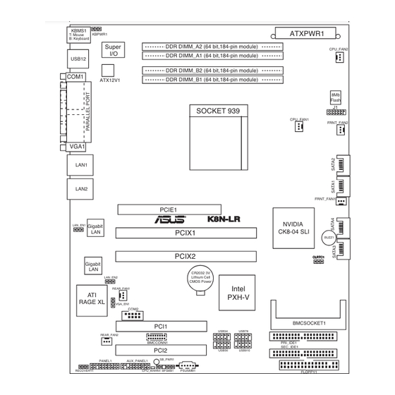
Page 23: Motherboard Layout
CK8-04 SLI BUZZ1 PCIX2 Gigabit CR2032 3V Lithium Cell LAN_EN2 CMOS Power Intel REAR_FAN1 PXH-V RAGE XL VGA_EN1 COM2 BMCSOCKET1 PCI1 USB34 USB78 REAR_FAN2 BMCCONN1 PRI_IDE1 SEC_IDE1 PCI2 USB56 USB910 SB_PWR1 PANEL1 AUX_PANEL1 PSUSMB1 RECOVERY1 CPU_WARN1 BPSMB1 FLOPPY1 ASUS K8N-LR... -
Page 24: Layout Contents
2.2.5 Layout Contents Slots/Sockets Page CPU sockets DDR DIMM sockets 2-11 PCI Express x16 slot 2-14 PCI/PCI-X slotos 2-15 Jumpers Page Clear RTC RAM (3-pin CLRTC) 2-16 Keyboard power (3-pin KBPWR1) 2-17 VGA graphics controller setting (3-pin VGA_EN1) 2-17 Gigabit LAN controller setting (3-pin LAN_EN1, LAN_EN2) 2-18 Force BIOS recovery setting (3-pin RECOVERY1) 2-19... - Page 25 ATX power connectors (24-pin ATXPWR1, 4-pin ATX12V) 2-25 Power supply SMBus connector (5-pin PSUSMB1) 2-26 10. BMC and Mini PCI connectors (16-pin BMCCONN1, 124-pin BMCSOCKET1) 2-26 11. System panel auxiliary connector (20-pin AUX_PANEL1) 2-27 12. System panel connector (20-pin PANEL1) 2-28 ASUS K8N-LR...
-
Page 26: Central Processing Unit (Cpu)
Locate the CPU socket on the motherboard. K8N-LR Gold Arrow K8N-LR CPU Socket 939 Before installing the CPU, make sure that the socket box is facing towards you and the load lever is on your left. Chapter 2: Hardware information... - Page 27 CPU! When the CPU is in place, push down the socket lever to secure the CPU. The lever clicks on the side tab to indicate that it is locked. ASUS K8N-LR...
-
Page 28: Installing The Heatsink And Fan
2.3.3 Installing the heatsink and fan The AMD Athlon™ 64 and AMD Opteron™ 64 processors require a specially designed heatsink and fan assembly to ensure optimum thermal condition Make sure that you use only qualified heatsink and fan assembly. Follow these steps to install the CPU heatsink and fan. Place the heatsink on top of the installed CPU, making sure that the heatsink fits properly on the retention module base. - Page 29 fits the retention mechanism module base, otherwise you cannot snap the retention bracket in place. Push down the retention bracket lock on the retention mechanism to secure the heatsink and fan to the module base. ASUS K8N-LR...
- Page 30 CPU_FAN2. CPU_FAN2 CPU_FAN2 +12V Rotation CPU_FAN1 Rotation CPU_FAN1 K8N-LR +12V K8N-LR CPU Fan Connectors Do not forget to connect the CPU fan connector! Hardware monitoring errors can occur if you fail to plug this connector. 2-10 Chapter 2: Hardware information...
-
Page 31: System Memory
Inline Memory Modules (DIMM) sockets. The following figure illustrates the location of the sockets: 104 Pins 80 Pins K8N-LR DIMM_A2 DIMM_A1 DIMM_B2 DIMM_B1 K8N-LR 184-pin DDR DIMM Sockets Channel Sockets Channel A DIMM_A1 and DIMM_A2 Channel B DIMM_B1 and DIMM_B2 2.4.2 Memory Configurations You may install 64 MB, 128 MB, 256 MB, 512 MB, or 1 GB unbuffered ECC DDR DIMMs into the DIMM sockets using the memory configurations in this... -
Page 32: Installing A Dimm
2.4.3 Installing a DIMM Make sure to unplug the power supply before adding or removing DIMMs or other system components. Failure to do so may cause severe damage to both the motherboard and the components. Unlock a DIMM socket by DDR DIMM notch pressing the retaining clips outward. -
Page 33: Expansion Slots
Turn on the system and change the necessary BIOS settings, if any. See Chapter 4 for information on BIOS setup. Assign an IRQ to the card. Refer to the tables on the next page. Install the software drivers for the expansion card. ASUS K8N-LR 2-13... -
Page 34: Interrupt Assignments
2.5.3 Interrupt assignments Standard interrupt assignments Priority Standard Function System Timer Keyboard Controller – Programmable interrupt Communications Port (COM2) Communications Port (COM1)* IRQ holder for PCI steering* Floppy Disk Controller Printer Port (LPT1)* System CMOS/Real Time Clock IRQ holder for PCI steering* IRQ holder for PCI steering* IRQ holder for PCI steering* PS/2 Compatible Mouse Port*... -
Page 35: Pci/Pci-X Slots
The PCI-X frequency vary depending on the PCI-X slot configuration. Refer to the table below for PCI-X slot setup and corresponding frequency. PCI-X Frequency PCI-X 1 slot PCI-X 2 slot Frequency (PCIX1) (PCIX2) populated 133MHz populated 133MHz populated populated 100MHz ASUS K8N-LR 2-15... -
Page 36: Jumpers
Except when clearing the RTC RAM, never remove the cap on CLRTC jumper default position. Removing the cap will cause system boot failure! CLRTC1 K8N-LR Normal Clear CMOS (Default) K8N-LR Clear RTC RAM 2-16 Chapter 2: Hardware information... - Page 37 +5VSB lead, and a corresponding setting in the BIOS. KBPWR1 +5VSB (Default) K8N-LR K8N-LR Keyboard Power Setting VGA Graphics controller setting (3-pin VGA_EN1) These jumpers allow you to enable or disable the onboard ATI Rage XL video graphics controller. VGA_EN1...
- Page 38 ® BCM5721 Gigabit LAN controllers. The LAN_EN1 jumper controls the LAN1 port. The LAN_EN2 iumper controls the LAN2 port. LAN_EN1 K8N-LR Enable Disable (Default) K8N-LR LAN_EN1 Setting LAN_EN2 K8N-LR Enable Disable (Default) K8N-LR LAN_EN2 Setting 2-18 Chapter 2: Hardware information...
- Page 39 7. Replace the jumper cap from pins 1-2 to pins 2-3. 8. Reboot your computer. 9. Hold down the <Del> key during the boot process and enter BIOS setup to re-enter data. RECOVERY1 Normal BIOS recovery K8N-LR (Default) K8N-LR BIOS Recovery Setting ASUS K8N-LR 2-19...
-
Page 40: Connectors
Connectors 2.7.1 Rear panel connectors PS/2 mouse port (green). This port is for a PS/2 mouse. Parallel port. This 25-pin port connects a parallel printer, a scanner, or other devices. LAN2 (RJ-45) port. Supported by the BROADCOM BCM5721 Gigabit ® LAN controller, this port allows Gigabit connection to a Local Area Network (LAN) through a network hub. -
Page 41: Internal Connectors
NOTE: Orient the red markings on the floppy ribbon cable to PIN 1. K8N-LR K8N-LR Floppy Disk Drive Connector IDE connectors (40-1 pin PRI_IDE1, SEC_IDE1) These connectors are for Ultra DMA 133/100/66/33 signal cables. The Ultra DMA 133/100/66/33 signal cable has three connectors: a... -
Page 42: Serial Ata Connectors
RSATA_RXP2 RSATA_TXP2 SATA1 RSATA_TXN2 RSATA_RXN2 RSATA_RXP2 K8N-LR RSATA_TXP2 SATA4 RSATA_TXN2 RSATA_RXN2 RSATA_RXP2 RSATA_TXP2 RSATA_TXN2 SATA3 RSATA_RXN2 RSATA_RXP2 K8N-LR SATA Connectors The actual data transfer rate depends on the speed of Serial ATA hard disks installed. 2-22 Chapter 2: Hardware information... - Page 43 Do not forget to connect the fan cables to the fan connectors. Lack of sufficient air flow inside the system may damage the motherboard components. These are not jumpers! DO NOT place jumper caps on the fan connectors! • All fan features the ASUS Smart Fan technology. +12V CPU_FAN2 CPU_FAN2 Rotation...
-
Page 44: Serial Port Connector (10-1 Pin Com)
This connector is for a serial (COM) port. Connect the serial port module cable to this connector, then install the module to a slot opening at the back of the system chassis. COM2 K8N-LR K8N-LR Serial Port2 (COM2) Connector 2-24 Chapter 2: Hardware information... -
Page 45: Atx Power Connectors (24-Pin Atxpwr1, 4-Pin Atx12V)
Make sure that your power supply unit (PSU) can provide at least the minimum power required by your system. See the table below for details. ATXPWR1 ATX12V1 ATXPWR1 24-pin Power Connector ATX12V1 +12V DC +12V DC K8N-LR For Power Supply with 20-pin Power Connector K8N-LR ATX Power Connectors ASUS K8N-LR 2-25... -
Page 46: Power Supply Smbus Connector (5-Pin Psusmb)
SMBus host and/or other SMBus devices using the SMBus interface. PSUSMB1 K8N-LR K8N-LR Power Supply SMBus Connector 10. BMC and Mini PCI connectors (16-pin BMCCONN, 124-pin BMCSOCKET1[optional]) These connectors are for the ASUS server management cards. BMCCONN1 K8N-LR K8N-LR BMC Connector BMCSOCKET1 K8N-LR... -
Page 47: System Panel Auxiliary Connector (20-Pin Aux_Panel)
11. System panel auxiliary connector (20-pin AUX_PANEL1) This connector supports several server system functions. AUX_PANEL1 K8N-LR K8N-LR A uxiliary Panel Connector • Chassis Intrusion connector (3-pin CASEOPEN) This lead is for a chassis with an intrusion detection feature. This requires an external detection mechanism such as a chassis intrusion sensor or microswitch. -
Page 48: System Panel Connector (20-Pin Panel)
12. System panel connector (20-pin PANEL1) This connector supports several chassis-mounted functions. PANEL1 K8N-LR K8N-LR System Panel Connector The system panel connector is color-coded for easy connection. Refer to the connector description below for details. • System power LED (Green 3-pin POWERLED) This 3-pin connector is for the system power LED. -
Page 49: Chapter 3: Powering Up
This chapter describes the power up sequence, the POST messages, and ways of shutting down the system. Powering up... -
Page 50: Chapter Summary
Chapter summary Starting up for the first time ..........3-1 Powering off the computer ........... 3-2 ASUS K8N-LR... -
Page 51: Starting Up For The First Time
Check the jumper settings and connections or call your retailer for assistance. At power on, hold down the <Del> key to enter the BIOS Setup. Follow the instructions in Chapter 4. ASUS K8N-LR... -
Page 52: Powering Off The Computer
Powering off the computer 3.2.1 Using the OS shut down function If you are using Windows 2000/2003 Server: ® Click the Start button then click Shut Down... Select Shut Down from the What do you want the computer to do? list box. -
Page 53: Chapter 4: Bios Setup
This chapter tells how to change the system settings through the BIOS Setup menus. Detailed descriptions of the BIOS parameters are also provided. BIOS setup... - Page 54 Chapter summary Managing and updating your BIOS ........4-1 BIOS setup program ............4-10 Main menu ................4-13 Advanced menu ..............4-18 Power menu ................ 4-30 Boot menu ................4-34 Exit menu ................4-38 ASUS K8N-LR...
-
Page 55: Managing And Updating Your Bios
The following utilities allow you to manage and update the motherboard Basic Input/Output System (BIOS) setup. ASUS AFUDOS (Updates the BIOS in DOS mode using a bootable floppy disk.) ASUS CrashFree BIOS 2 (Updates the BIOS using a bootable floppy disk or the motherboard support CD when the BIOS file fails or gets... -
Page 56: Afudos Utility
Windows 2000 environment ® To create a set of boot disks for Windows 2000: ® a. Insert a formatted, high density 1.44 MB floppy disk into the drive. b. Insert the Windows 2000 CD to the optical drive. ® c. Click Start, then select Run. d. -
Page 57: Updating The Bios File
Updating the BIOS file To update the BIOS file using the AFUDOS utility: Visit the ASUS website (www.asus.com) and download the latest BIOS file for the motherboard. Save the BIOS file to a bootable floppy disk. Write the BIOS filename on a piece of paper. You need to type the exact BIOS filename at the DOS prompt. - Page 58 The utility verifies the file and starts updating the BIOS. A:\>afudos /iK8N-LR.ROM /pbnc AMI Firmware Update Utility - Version 1.19(ASUS V2.07(03.11.24BB)) Copyright (C) 2002 American Megatrends, Inc. All rights reserved. WARNING!! Do not turn off power during flash BIOS Reading file ..done Reading flash ..
-
Page 59: Asus Crashfree Bios 2 Utility
4.1.3 ASUS CrashFree BIOS 2 utility The ASUS CrashFree BIOS 2 is an auto recovery tool that allows you to restore the BIOS file when it fails or gets corrupted during the updating process. You can update a corrupted BIOS file using the motherboard support CD or the floppy disk that contains the updated BIOS file. -
Page 60: Recovering The Bios From The Support Cd
Restart the system after the utility completes the updating process. The recovered BIOS may not be the latest BIOS version for this motherboard. Visit the ASUS website (www.asus.com) to download the latest BIOS file. Chapter 4: BIOS setup... -
Page 61: Asus Update Utility
4.1.4 ASUS Update utility The ASUS Update is a utility that allows you to manage, save, and update the motherboard BIOS in Windows environment. The ASUS Update utility ® allows you to: • Save the current BIOS file • Download the latest BIOS file from the Internet •... -
Page 62: Updating The Bios Through The Internet
To update the BIOS through the Internet: Launch the ASUS Update utility from the Windows desktop by clicking ® Start > Programs > ASUS > ASUSUpdate > ASUSUpdate. The ASUS Update main window appears. Select Update BIOS from Select the ASUS FTP site... -
Page 63: Updating The Bios Through A Bios File
To update the BIOS through a BIOS file: Launch the ASUS Update utility from the Windows desktop by ® clicking Start > Programs > ASUS > ASUSUpdate > ASUSUpdate. The ASUS Update main window appears. Select Update BIOS from a file option from the drop-down menu, then click Next. -
Page 64: Bios Setup Program
The BIOS setup screens shown in this section are for reference purposes only, and may not exactly match what you see on your screen. • Visit the ASUS website (www.asus.com) to download the latest BIOS file for this motherboard. 4-10 Chapter 4: BIOS setup... -
Page 65: Bios Menu Screen
At the bottom right corner of a menu screen are the navigation keys for that particular menu. Use the navigation keys to select items in the menu and change the settings. Some of the navigation keys differ from one screen to another. ASUS K8N-LR 4-11... -
Page 66: Menu Items
[English] For example, selecting Main shows the Use [+] or [-] to Primary IDE Master :[ST320413A] configure system time. Primary IDE Slave :[ASUS CD-S340] Secondary IDE Master :[Not Detected] Main menu items. Secondary IDE Slave :[Not Detected] Third IDE Master... -
Page 67: Main Menu
Allows you to set the system date. 4.3.3 Legacy Diskette A/B Sets the type of floppy drive installed. Configuration options: [Disabled] [360K, 5.25 in.] [1.2M , 5.25 in.] [720K , 3.5 in.] [1.44M, 3.5 in.] [2.88M, 3.5 in.] ASUS K8N-LR 4-13... -
Page 68: Primary And Secondary Master/Slave, Third
4.3.4 Primary and Secondary Master/Slave, Third, Fourth, Fifth, and Sixth IDE Master The BIOS automatically detects the connected IDE devices. There is a separate sub-menu for each IDE device. Select a device item, then press <Enter> to display the IDE device information. Primary IDE Master Device : Hard Disk... -
Page 69: Ide Configuration
Enables or disables the SATA1 IDE Interface. Configuration options: [Disabled] [Enabled] Hard Disk Write Protect [Disabled] Enables or disables the hard disk wirte protection. This will be effective only if device is accessed through BIOS. Configuration options: [Disabled] [Enabled] ASUS K8N-LR 4-15... - Page 70 IDE Detect Time Out [35] Selects the time out value for detecting ATA/ATAPI devices. Configuration options: [0] [5] [10] [15] [20] [25] [30] [35] ATA(PI) 80Pin Cable Detection [Host] Selects the mechanism for detecting 80Pin ATA(PI) Cable. Configuration options: [Host & Device] [Host] [Device] First Boot Device from [P-ATA] Selects the First Boot Device.
-
Page 71: System Information
Processor Type : AMD Opteron(tm) Processor 146 Speed : 2000 MHz Count System Memory Size : 256MB AMI BIOS Displays the auto-detected BIOS information Processor Displays the auto-detected CPU specification System Memory Displays the auto-detected system memory ASUS K8N-LR 4-17... -
Page 72: Advanced Menu
Advanced menu The Advanced menu items allow you to change the settings for the CPU and other system devices. Take caution when changing the settings of the Advanced menu items. Incorrect field values can cause the system to malfunction. CPU Configuration Configure CPU. -
Page 73: Chipset
: 11 CLK Select Screen Row Refresh Cycle (Trfc) : 14 CLK Select Item Read Write Delay (Trwt) : 4 CLK Change Option Read Preamble : 5.5 ns General Help Asynchronous Latency : 7 ns Save and Exit Exit ASUS K8N-LR 4-19... -
Page 74: Memory Configuration
Memory Configuration The memory configuration menu allows you to change the memory settings. Memory Configuration MEMCLK can be set by the code using Memclock Mode [Auto] AUTO, or if you use CMD-ADDR Timing Mode [ 1T] LIMIT, you can set Burst Length [4 Beats] one of the standard... -
Page 75: Ecc Configuration
Disables or sets the L2 Cache BG Scrub. This item allows the L2 data cache RAM to be corrected when idle. Configuration options: [Disabled] [40ns] [80ns] [160na] [320ns] [640ns] [1.28us] [2.56us] [5.12us] [10.2us] [20.5us] [41.0us] [81.9us] [163.8us] [327.7us] [655.4us] [1.31ms] [2.62ms] [5.24ms] [10.49ms] [20.97ms] [42.00ms] [84.00ms] ASUS K8N-LR 4-21... -
Page 76: Southbridge Configuration
Data Cache BG Scrub [Disabled] Disables or sets the Data Cache BG Scrub. This item allows the data cache BG Scrub RAM to be corrected when idle. Configuration options: [Disabled] [40ns] [80ns] [160na] [320ns] [640ns] [1.28us] [2.56us] [5.12us] [10.2us] [20.5us] [41.0us] [81.9us] [163.8us] [327.7us] [655.4us] [1.31ms] [2.62ms] [5.24ms] [10.49ms] [20.97ms] [42.00ms] [84.00ms] Power Down Control [Auto]... -
Page 77: Onboard Devices Configuration
Allows you to select reciever or transmit pin for Serial Port2 (IR Mode). Configuration options: [SINB/SOUTB] [IRRX/IRTX] IR Duplex Mode [Half Duplex] Allows you to select full or half duplex for Serial Port2 (IR Mode). Configuration options: [Half Duplex] [Full Duplex] ASUS K8N-LR 4-23... - Page 78 Parallel Port Address [378] Allows you to select the Parallel Port base addresses. Configuration options: [Disabled] [378] [278] [3BC] Parallel Port Mode [Normal] Allows you to select the Parallel Port mode. Configuration options: [Normal] [Bi-Directional] [EPP] [ECP] The following items appear when the Parallel Port Mode is set to EPP. EPP Version [1.9] Allows you to select the Parallel Port EPP version.
-
Page 79: Pci Pnp
PCI VGA card even if requested. Configuration options: [No] [Yes] Palette Snooping [Disabled] When set to [Enabled], the pallete snooping feature informs the PCI devices that an ISA graphics device is installed in the system so that the latter can function correctly. Configuration options: [Disabled] [Enabled] ASUS K8N-LR 4-25... -
Page 80: Mps Configuration
IRQ-xx assigned to [PCI Device] When set to [PCI Device], the specific IRQ is free for use of PCI/PnP devices. When set to [Reserved], the IRQ is reserved for legacy ISA devices. Configuration options: [PCI Device] [Reserved] 4.4.5 MPS Configuration The items in this menu allows you to configure the Multi-Processor Table. - Page 81 Configuration options: [ANSI] [VT100] [VT-UTF8] VT-UTF8 Combo Key Support [Enabled] Enables or disables the VT-UTF8 combo key support for ANSI or VT100 terminals. Configuration options: [Disabled] [Enabled] Media Type [Serial] Selects the media for console redirection. Configuration options: [Serial] [LAN] [Serial+LAN] ASUS K8N-LR 4-27...
-
Page 82: Usb Configuration
4.4.7 USB Configuration The items in this menu allows you to change the USB-related features. Select an item then press <Enter> to display the configuration options. USB Configuration Enables USB host controllers. Module Version - 2.24.0-F.4 USB Devices Enabled: None USB Controller Support [USB 1.1+USB 2.0] Legacy USB Support... -
Page 83: Hyper Transport Configuration
Enabled/Disabled Cool AMD Cool’N’Quiet Configuration 'N'Quiet Cool’N’Quiet [Enabled] Cool ʻNʼ Quiet [Enabled] Enables or disables the ASUS AMD Cool ʻnʼ Quiet technology feature. Configuration options: [Enabled] [Disabled] 4.4.9 Hyper Transport Configuration Hyper Transport Configuration The Hyper Transport link will run at this... -
Page 84: Power Menu
Power menu The Power menu items allow you to change the settings for the ACPI and Advanced Power Management (APM) features. Select an item then press <Enter> to display the configuration options. ACPI 2.0 Support [No] Select the ACPI state ACPI APIC Support [Enabled] used for System... -
Page 85: Apm Configuration
Soft-off mode. Configuration options: [Disabled] [Enabled] RI Resume [Disabled] When set to [Enabled], the system enables the RI to generate a wake event while the computer is in Soft-off mode. Configuration options: [Disabled] [Enabled] ASUS K8N-LR 4-31... - Page 86 Power On By PS/2 Keyboard [Disabled] Allows you to disable or enable the PS/2 Power-On by keyboard feature. This feature requires an ATX power supply that provides at least 1A on the +5VSB lead. Configuration options: [Disabled] [Enabled] Resume On PS/2 Mouse [Disabled] When set to [Enabled], this parameter allows you to use the PS/2 mouse to turn on the system.
-
Page 87: Hardware Monitor
field shows N/A. Select [Ignored] if you do not wish to display the detected temperatures. Smart Fan Control [Enabled] Allows you to enable or disable the ASUS Smart Fan feature that smartly adjusts the fan speeds for more efficient system operation. Configuration options: [Disabled] [Enabled] The CPU1 Target Temperature and MB Target Temperature items appear when you enable the Smart Fan Control feature. -
Page 88: Boot Menu
Boot Device Priority sequence from the 1st Boot Device [1st FLOPPY DRIVE] available devices. 2nd Boot Device [PM-ST330620A] 3rd Boot Device [PS-ASUS CD-S360] A device enclosed in parenthesis has been disabled in the corresponding type menu. Select Screen Select Item... -
Page 89: Boot Settings Configuration
Allows you to enable or disable the full screen logo display feature. Configuration options: [Disabled] [Enabled] Set this item to [Enabled] to use the ASUS MyLogo2™ feature. Bootup Num-Lock [On] Allows you to select the power-on state for the NumLock. -
Page 90: Security
4.6.3 Security The Security menu items allow you to change the system security settings. Select an item then press <Enter> to display the configuration options. Security Settings <Enter> to change password. Supervisor Password : Not Installed <Enter> again to User Password : Not Installed disabled password. -
Page 91: Change User Password
<Enter>. Confirm the password when prompted. The message “Password Installed” appears after you set your password successfully. To change the user password, follow the same steps as in setting a user password. ASUS K8N-LR 4-37... -
Page 92: Exit Menu
Clear User Password Select this item to clear the user password. Password Check [Setup] When set to [Setup], BIOS checks for user password when accessing the Setup utility. When set to [Always], BIOS checks for user password both when accessing Setup and booting the system. Configuration options: [Setup] [Always] Exit menu The Exit menu items allow you to load the optimal or failsafe default values... -
Page 93: Discard Changes
Setup menus. When you select this option or if you press <F5>, a confirmation window appears. Select Ok to load default values. Select Exit & Save Changes or make other changes before saving the values to the non-volatile RAM. ASUS K8N-LR 4-39... - Page 94 4-40 Chapter 4: BIOS setup...
- Page 95 This chapter provides instructions for setting up, creating, and configuring RAID sets using the available utilities. R AID configuration...
-
Page 96: Chapter 5: Raid Configuration
Chapter summary Setting up RAID ..............5-1 NVIDIA RAID configurations ..........5-3 ® ASUS K8N-LR... -
Page 97: Setting Up Raid
If you want to boot the system from a hard disk drive included in a created RAID set, copy first the RAID driver from the support CD to a floppy disk before you install an operating system to the selected hard disk drive. Refer to Chapter 6 for details. ASUS K8N-LR... -
Page 98: Installing Hard Disk Drives
5.1.2 Installing hard disk drives The motherboard supports Serial ATA hard disk drives for RAID set configuration. For optimal performance, install identical drives of the same model and capacity when creating a disk array. To install the SATA hard disks for RAID configuration: Install the SATA hard disks into the drive bays following the instructions in the system user guide. -
Page 99: Nvidia ® Raid Configurations
Refer to Chapter 4 for details on entering and navigating through the BIOS Setup. • The RAID BIOS setup screens shown in this section are for reference only, and may not exactly match the items on your screen. ASUS K8N-LR... -
Page 100: Entering The Nvidia ® Raid Utility
5.2.2 Entering the NVIDIA RAID Utility ® To enter the NVIDIA RAID Utility: ® Restart the computer. During POST, press <F10> to display the utility main menu. NVIDIA RAID Utility Oct 5 2004 - Define a New Array - RAID Mode: Striping Striping Block: Optimal... -
Page 101: Creating A Raid 0 Set (Stripe)
Striping Striping Block: Optimal Free Disks Array Disks Disk Model Name Disk Model Name 1.0.M XXXXXXXXXXXXXXXXXX 1.0.M XXXXXXXXXXXXXXXXXX 1.1.M XXXXXXXXXXXXXXXXXX [→] Add 2.0.M XXXXXXXXXXXXXXXXXX 2.1.M XXXXXXXXXXXXXXXXXX [←] Del [F6] Back [F7] Finish [TAB] Navigate [↑↓] Select [ENTER] Popup ASUS K8N-LR... - Page 102 After selecting the hard disk drives, press Clear disk data? <F7> to create the RAID 0 set. A pop-up [Y] YES [N] Cancel window appears. Press <Y> to delete all data from the hard disk drives, or <N> to continue creating the RAID set without deleting the data on the disks. You will lose all data on the drives if you clear the disk data! The utility displays the created RAID 0 set.
-
Page 103: Creating A Raid 1 Set (Mirror)
RAID set. Press <N> to backup exisitng data to a target hard disk drive. You will lose all data on the drives if you clear the disk data! The utility displays the created RAID 1 set. Press <Ctrl+X> to save your settings and exit the utility.0 ASUS K8N-LR... -
Page 104: Rebuilding A Raid Set
5.2.5 Rebuilding a RAID set To rebuild a RAID set: From the Array List, use the up or down arrow keys to select the RAID set you want to rebuild, then press <Enter>. The RAID set details appear. NVIDIA RAID Utility Oct 5 2004 - Array List - Boot... -
Page 105: Deleting A Raid Array
[N] Cancel You will lose all data on the drives if you delete a disk array! The Define a New Array menu appears when you press <Y>. Create a new RAID set following the instructions in the previous sections.. ASUS K8N-LR... -
Page 106: Clearing The Disk Data
5.2.7 Clearing the disk data You will lose all data when you clear a disk! To clear the disk data: From the Array List, use the up or down arrow keys to select a RAID set, then press <Enter>. The RAID set details appear. NVIDIA RAID Utility Oct 5 2004 - Array List -... -
Page 107: Chapter 6: Driver Installation
This chapter provides instructions for installing the necessary drivers for different system components. Driver installation... - Page 108 Chapter summary RAID driver installation ............6-1 LAN driver installation ............6-3 Support CD information ............6-4 ASUS K8N-LR...
-
Page 109: Raid Driver Installation
D) Create NVIDIA nForce(TM) SATA RAID for Windows 2003 64 bit Driver Disk Please choose A TO D: Place a blank, high-density floppy disk to the floppy disk drive. The utility erases all data in the floppy disk before copying the RAID drivers. ASUS K8N-LR... - Page 110 Type the letter of the option you like to select, then press <Enter>. For example, if you want to create an NVIDIA nForce(TM) SATA RAID driver disk for Windows 2003 system, press <C>, then press <Enter>. The RAID drivers are copied to the floppy disk. After creating a RAID driver disk, eject the floppy disk, then write-protect it to prevent computer virus infection.
-
Page 111: Lan Driver Installation
CD to locate the file ASSETUP.EXE from the BIN folder. Double-click the ASSETUP.EXE to run the CD. Click the Broadcom 5721 Driver option to begin installation. Click Next when the InstallShield Wizard window appears. Follow screen instructions to continue installation. ASUS K8N-LR... -
Page 112: Support Cd Information
The contents of the support CD are subject to change at any time without notice. Visit the ASUS website (www.asus.com) for updates. 6.3.1 Running the support CD Place the support CD to the optical drive. -
Page 113: Drivers Menu
The ATI Rage XL Display Driver appears only under ® 2000 OS. Broadcom 5721 Driver Installs the Broadcom 5721 driver.See page 6-3 for details. Broadcom 5721 NetXtreme Software Utility Installs the Broadcom NetXtreme software application. Refer to the application help file for details. ASUS K8N-LR... -
Page 114: Management Software
The Management Software menu shows the available server management software applications. Install ASUS Network Utility Installs the ASUS Network Utility. Refer to the application help file for details. ASWM Installs the ASWM (ASUS Server Web-based Managment). Refer to the application help file for details. -
Page 115: Utilities
Reader V7.0 is for opening, viewing, and printing ® documents in Portable Document Format (PDF). ASUS Screen Saver Bring life to your idle screen by installing the ASUS screen saver. ASUS Update The ASUS Update utility that allows you to update the motherboard BIOS in Windows environment. - Page 116 Chapter 6: Driver installation...
-
Page 117: Appendix: Reference Information
This appendix includes additional information that you may refer to when configuring the motherboard. Reference information... - Page 118 Appendix summary K8N-LR block diagram ............A-1 ASUS K8N-LR...
-
Page 119: K8N-Lr Block Diagram
K8N-LR block diagram ASUS K8N-LR... - Page 120 Appendix A: Reference information...
Need help?
Do you have a question about the K8N-LR and is the answer not in the manual?
Questions and answers