Table of Contents
Advertisement
Advertisement
Table of Contents

Related Manuals for Asus AT5NM10-I


Summary of Contents for Asus AT5NM10-I
- Page 1 AT5NM10-I E5179_AT5NM10-I.indb 1 12/22/09 5:55:35 PM...
- Page 2 Product warranty or service will not be extended if: (1) the product is repaired, modified or altered, unless such repair, modification of alteration is authorized in writing by ASUS; or (2) the serial number of the product is defaced or missing.
-
Page 3: Table Of Contents
Contents Notices ......................v Safety information ..................vi About this guide ..................vi AT5NM10-I specifications summary ............viii Chapter 1: Product introduction Before you proceed ..............1-1 Motherboard overview ..............1-2 1.2.1 Motherboard layout ............1-2 1.2.2 Layout contents ............... 1-2 Central Processing Unit (CPU) ........... - Page 4 Boot Device Priority ............2-12 2.6.2 Boot Settings Configuration .......... 2-12 2.6.3 Security ................. 2-13 Tools menu ................. 2-15 2.7.1 ASUS EZ Flash 2 ............2-15 2.7.2 Express Gate ..............2-15 2.7.3 AI NET 2................ 2-16 Exit menu ..................2-16 E5179_AT5NM10-I.indb 4...
-
Page 5: Notices
Complying with the REACH (Registration, Evaluation, Authorisation, and Restriction of Chemicals) regulatory framework, we published the chemical substances in our products at ASUS REACH website at http://green.asus.com/english/REACH.htm. DO NOT throw the motherboard in municipal waste. This product has been designed to enable proper reuse of parts and recycling. -
Page 6: Safety Information
Safety information Electrical safety • To prevent electric shock hazard, disconnect the power cable from the electric outlet before relocating the system. • When adding or removing devices to or from the system, ensure that the power cables for the devices are unplugged before the signal cables are connected. If possible, disconnect all power cables from the existing system before you add a device. -
Page 7: Conventions Used In This Guide
Refer to the following sources for additional information and for product and software updates. ASUS websites The ASUS website provides updated information on ASUS hardware and software products. Refer to the ASUS contact information. Optional documentation Your product package may include optional documentation, such as warranty flyers, that may have been added by your dealer. -
Page 8: At5Nm10-I Specifications Summary
- 2 x 240-pin DIMM sockets support maximum 4GB unbuffered non-ECC 800/667 MHz DDR2 memory modules Refer to www.asus.com or this user manual for the Memory QVL (Qualified Vendors Lists). ** When you install a total memory of 4GB capacity... - Page 9 AT5NM10-I specifications summary Internal connectors 2 x USB 2.0/1.1 connector supports additional 4 USB 2.0/1.1 ports 1 x CPU fan connector 1 x Chassis fan connector 1 x Chassis intrusion connector 1 x Optical S/PDIF Out connector 1 x Speaker connector...
-
Page 10: Chapter 1: Product Introduction
Chapter 1 Product introduction Thank you for buying an ASUS AT5NM10-I motherboard! ® Before you start installing the motherboard, and hardware devices on it, check the items in your motherboard package. Refer to page ix for the list of accessories. -
Page 11: Motherboard Overview
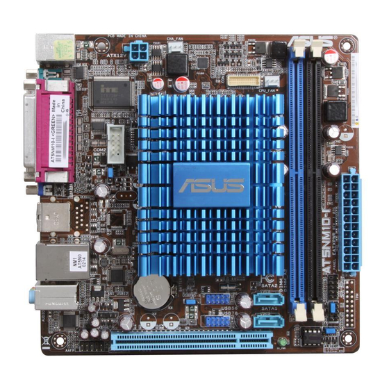
System panel connector (10-1 pin F_PANEL) 1-15 USB connector (10-1 pin USB56, USB78) 1-13 DIMM socket Digital audio connector (4-1 pin SPDIF_OUT) 1-17 System panel connector (10-1 pin F_PANEL) 1-16 Front panel audio connector (10-1 pin AAFP) 1-15 ASUS AT5NM10-I E5179_AT5NM10-I.indb 2 12/22/09 5:55:43 PM... -
Page 12: Central Processing Unit (Cpu)
Central Processing Unit (CPU) The motherboard comes with an onboard Dual-Core Intel Atom™ D510 processor and a ® specially designed CPU heatsink. Ensure that the CPU fan cable is connected to the onboard CPU_FAN connector. System memory 1.4.1 Overview The motherboard comes with two Double Data Rate 2 (DDR2) Dual Inline Memory Modules (DIMM) sockets. -
Page 13: Memory Configurations
• When you install 4GB memory on the motherboard, the memory that the system can detect is less than 4GB. • This motherboard does not support DIMMs made up of 256 megabits (Mb) chips or less. AT5NM10-I Motherboard Qualified Vendors Lists (QVL) DDR2-667 MHz capability DIMM... - Page 14 DDR2-667 MHz capability DIMM Chip Vendor Part No. Size Chip NO. Timing Voltage support Brand A* B* Century CENTURY 1G 1024MB Hynix HY5PS12821AFP-Y5 • Century CENTURY 1G 1024MB Nanya NT5TU64M8AE-3C • KINGBOX 512MB 667MHz 512MB EPD264082200-4 • KINGBOX DDRII 1G 667MHz 1024MB EPD264082200-4 •...
- Page 15 1024MB Samsung K4T51083QG-HCF7 • • SAMSUNG M37875663QZ3-CF7 2048MB Samsung K4T1G084QQ-HCF7 • • SAMSUNG M378T5263AZ3-CF7 4096MB Samsung K4T2G084QA-HCF7 • • Super T800UB1GC4 1024MB Super 1.8V • • Talent Talent (continued on the next page) ASUS AT5NM10-I E5179_AT5NM10-I.indb 6 12/22/09 5:55:50 PM...
- Page 16 DIMM support: • A*: Supports one module inserted into either slot. • B*: Supports one pair of modules inserted into both the slots. Visit the ASUS website at www.asus.com for the latest QVL. Chapter 1: Product introduction E5179_AT5NM10-I.indb 7 12/22/09 5:55:52 PM...
-
Page 17: Expansion Slot
Install the software drivers for the expansion card. 1.5.3 PCI slot The PCI slot supports cards such as a LAN card, SCSI card, USB card, and other cards that comply with PCI specifications. ASUS AT5NM10-I E5179_AT5NM10-I.indb 8 12/22/09 5:55:53 PM... -
Page 18: Jumpers
Jumpers Clear RTC RAM (3-pin CLRTC) This jumper allows you to clear the Real Time Clock (RTC) RAM in CMOS. You can clear the CMOS memory of date, time, and system setup parameters by erasing the CMOS RTC RAM data. The onboard button cell battery powers the RAM data in CMOS, which include system setup information such as system passwords. -
Page 19: Usb Device Wake-Up
USB ports. PS2_USBPW1-4 +5VSB (Default) AT5NM10-I Keyboard Power Setting The total current consumed must NOT exceed the power supply capability (+5VSB) whether under normal condition or in sleep mode. USB device wake-up (3-pin USBPW5-8) Set this jumper to +5V to wake up the computer from S1 sleep mode (CPU stopped, DRAM refreshed, system running in low power mode) using the connected USB devices. -
Page 20: Connectors
Connectors 1.7.1 Rear panel connectors PS/2 Mouse port (green). This port is for a PS/2 mouse. Parallel port. This 25-pin port connects a parallel printer, a scanner, or other devices. LAN (RJ-45) port. This port allows Gigabit connection to a Local Area Network (LAN) through a network hub. -
Page 21: Internal Connectors
• DO NOT forget to connect the 4-pin ATX +12V power plug. Otherwise, the system will not boot up. • If you are uncertain about the minimum power supply requirement for your system, refer to the Recommended Power Supply Wattage Calculator at http://support.asus. com/PowerSupplyCalculator/PSCalculator.aspx?SLanguage=en-us for details. ASUS AT5NM10-I 1-12 E5179_AT5NM10-I.indb 12... - Page 22 Serial ATA connectors (7-pin SATA1, SATA2) These connectors are for the Serial ATA signal cables for Serial ATA 3Gb/s hard disk drives and optical disk drives. The Serial ATA 3Gb/s is backward compatible with the Serial ATA 1.5Gb/s specification. The data transfer rate of the Serial ATA 3Gb/s is faster than the standard parallel ATA (133 MB/s).
- Page 23 Remove the jumper caps only when you intend to use the chassis intrusion detection feature. Internal speaker connector (4-pin SPEAKER) The 4-pin connector is for the chassis-mounted system warning speaker. The speaker allows you to hear system beeps and warnings. ASUS AT5NM10-I 1-14 E5179_AT5NM10-I.indb 14 12/22/09 5:56:02 PM...
- Page 24 CPU and chassis fan connectors (3-pin CPU_FAN, 3-pin CHA_FAN) Connect the fan cables to the fan connectors on the motherboard, ensuring that the black wire of each cable matches the ground pin of the connector. Do not forget to connect the fan cables to the fan connectors. Insufficient air flow inside the system may damage the motherboard components.
- Page 25 This 2-pin connector is for the chassis-mounted reset button for system reboot without turning off the system power. LVDS connector (30-pin CON1) This connector is for a LCD monitor that supports Low-voltage differential signaling (LVDS) interface. ASUS AT5NM10-I 1-16 E5179_AT5NM10-I.indb 16 12/22/09 5:56:05 PM...
- Page 26 This connector is for an additional Sony/Philips Digital Interface (S/PDIF) port. Connect the S/PDIF Out module cable to this connector, then install the module to a slot opening at the back of the system chassis. AT5NM10-I Digital audio connector The S/PDIF module is purchased separately. 1-17 Chapter 1: Product introduction E5179_AT5NM10-I.indb 17...
-
Page 27: Software Support
The contents of the Support DVD are subject to change at any time without notice. Visit the ASUS website at www.asus.com for updates. To run the Support DVD Place the Support DVD to the optical drive. -
Page 28: Chapter 2: Bios Information
BIOS in the future. Copy the original motherboard BIOS using the ASUS Update utility. 2.1.1 ASUS Update utility The ASUS Update is a utility that allows you to manage, save, and update the motherboard BIOS in Windows environment. ®... -
Page 29: Asus Ez Flash 2
Follow the onscreen instructions to complete the updating process. 2.1.2 ASUS EZ Flash 2 The ASUS EZ Flash 2 feature allows you to update the BIOS without using an OS-based utility. Before you start using this utility, download the latest BIOS file from the ASUS website at www.asus.com. -
Page 30: Asus Crashfree Bios
2.1.3 ASUS CrashFree BIOS The ASUS CrashFree BIOS is an auto recovery tool that allows you to restore the BIOS file when it fails or gets corrupted during the updating process. You can restore a corrupted BIOS file using the motherboard support DVD or a removable device that contains the updated BIOS file. -
Page 31: Bios Setup Program
• The BIOS setup screens shown in this section are for reference purposes only, and may not exactly match what you see on your screen. • Visit the ASUS website at www.asus.com to download the latest BIOS file for this motherboard. -
Page 32: System Time
2.3.1 System Time [xx:xx:xx] Allows you to set the system time. 2.3.2 System Date [Day xx/xx/xxxx] Allows you to set the system date. 2.3.3 SATA 1/2 While entering Setup, the BIOS automatically detects the presence of SATA devices. There is a separate sub-menu for each SATA device. Select a device item then press <Enter> to display the SATA device information. -
Page 33: Storage Configuration
Take caution when changing the settings of the Advanced menu items. Incorrect field values can cause the system to malfunction. BIOS SETUP UTILITY Main Advanced Power Boot Tools Exit Configure CPU. CPU Configuration Chipset Onboard Devices Configuration USB Configuration PCIPnP ASUS AT5NM10-I E5179_AT5NM10-I.indb 6 12/22/09 5:56:15 PM... -
Page 34: Cpu Configuration
2.4.1 CPU Configuration The items in this menu show the CPU-related information that the BIOS automatically detects. Max CPUID Value Limit [Disabled] Allows you to determine whether to limit CPUID maximum value. Set this item to [Disabled] for Windows XP operating system; set this item to [Enabled] for legacy operating system such as Windows NT4.0. -
Page 35: Onboard Devices Configuration
Appears only when the Parallel Port Mode is set to [ECP]. This item allows you to set the Parallel Port ECP DMA. Configuration options: [DMA0] [DMA1] [DMA3] Parallel Port IRQ [IRQ7] Allows you to select parallel port IRQ. Configuration options: [IRQ5] [IRQ7] ASUS AT5NM10-I E5179_AT5NM10-I.indb 8 12/22/09 5:56:16 PM... -
Page 36: Usb Configuration
2.4.4 USB Configuration The items in this menu allows you to change the USB-related features. Select an item then press <Enter> to display the configuration options. The Module Version and USB Devices Enabled items show the auto-detected values. If no USB device is detected, the item shows None. -
Page 37: Pci Pnp
Allows you to enable or disable the Advanced Configuration and Power Interface (ACPI) support in the Application-Specific Integrated Circuit (ASIC). When set to Enabled, the ACPI APIC table pointer is included in the RSDT pointer list. Configuration options: [Disabled] [Enabled] ASUS AT5NM10-I 2-10 E5179_AT5NM10-I.indb 10 12/22/09 5:56:17 PM... -
Page 38: Apm Configuration
2.5.4 APM Configuration Restore on AC Power Loss [Power Off] When set to [Power Off], the system goes into off state after an AC power loss. When set to [Power On], the system goes on after an AC power loss. When set to [Last State], the system goes into either off or on state, whatever the system state was before the AC power loss. -
Page 39: Boot Menu
Configuration options: [Removable Dev.] [Hard Drive] [ATAPI CD-ROM] [Disabled] • To select the boot device during system startup, press <F8> when ASUS Logo appears. • To access Windows OS in Safe Mode, do any of the following: ®... -
Page 40: Security
Wait For ‘F1’ If Error [Enabled] When set to Enabled, the system waits for the F1 key to be pressed when error occurs. Configuration options: [Disabled] [Enabled] Hit ‘DEL’ Message Display [Enabled] When set to [Enabled], the system displays the message Press DEL to run Setup during POST. - Page 41 When set to [Setup], BIOS checks for user password when accessing the Setup utility. When set to [Always], BIOS checks for user password both when accessing Setup and booting the system. Configuration options: [Setup] [Always] ASUS AT5NM10-I 2-14 E5179_AT5NM10-I.indb 14...
-
Page 42: Tools Menu
2.7.1 ASUS EZ Flash 2 Allows you to run ASUS EZ Flash 2. When you press <Enter>, a confirmation message appears. Use the left/right arrow key to select between [Yes] or [No], then press <Enter> to confirm your choice. See section 2.1.2 ASUS EZ Flash 2 for details. -
Page 43: Ai Net 2
Pressing <Esc> does not immediately exit this menu. Select one of the options from this Select Item Change Option menu or <F10> from the legend bar to exit. Enter Go to Sub-screen General Help General Help Save and Exit Save and Exit Exit Exit ASUS AT5NM10-I 2-16 E5179_AT5NM10-I.indb 16 12/22/09 5:56:25 PM...
Need help?
Do you have a question about the AT5NM10-I and is the answer not in the manual?
Questions and answers