Asus a7n8x User Manual
Motherboard diy troubleshooting guide
Hide thumbs
Also See for a7n8x:
- User manual (124 pages) ,
- Manual de démarrage rapide (17 pages) ,
- Manuel de l'utilisateur (114 pages)
Table of Contents
Advertisement
Advertisement
Table of Contents

Subscribe to Our Youtube Channel
Related Manuals for Asus a7n8x


Summary of Contents for Asus a7n8x
- Page 1 A7N8X User Guide...
- Page 2 Product warranty or service will not be extended if: (1) the product is repaired, modified or altered, unless such repair, modification of alteration is authorized in writing by ASUS; or (2) the serial number of the product is defaced or missing.
-
Page 3: Table Of Contents
1.10 Connectors ..............1-13 Chapter 2 - BIOS Information ............2-1 2.1 Managing and updating your BIOS ......2-2 2.1.1 Using ASUS AWDFLASH to update the BIOS....2-2 2.1.2 Using ASUS AWDFLASH to update the BIOS....2-3 Updating BIOS procedures........2-3 2.2 BIOS Setup Program ........... -
Page 4: Contents
Contents 2.3 Main Menu ..............2-9 2.3.1 Primary Master/Slave .......... 2-10 2.3.2 Secondary Master/Slave..........2-12 2.4 Advanced Menu ............2-13 2.4.1 Advanced BIOS Configuration ........2-14 2.4.2 Advanced Chipset Features........... 2-15 2.4.3 Integrated Peripherals............. 2-18 2.4.4 Power Management Setup ........2-20 2.4.5 PnP/PCI Configurations ........ -
Page 5: Fcc/Cdc Statements
FCC/CDC statements Federal Communications Commission Statement This device complies with FCC Rules Part 15. Operation is subject to the following two conditions: • This device may not cause harmful interference, and • This device must accept any interference received including interference that may cause undesired operation. -
Page 6: Safety Information
Safety information Electrical safety • To prevent electrical shock hazard, disconnect the power cable from the electrical outlet before relocating the system. • When adding or removing devices to or from the system, ensure that the power cables for the devices are unplugged before the signal cables are connected. -
Page 7: Conventions Used In This Guide
1. ASUS Websites The ASUS websites worldwide provide updated information on ASUS hardware and software products. The ASUS websites are listed in the ASUS Contact Information on page viii. 2. Optional Documentation Your product package may include optional documentation, such as warranty flyers, that may have been added by your dealer. -
Page 8: Asus Contact Information
Web site usa.asus.com Technical Support Telephone (General) +1-502-995-0883 (Notebook) +1-510-739-3777 Support fax +1-502-933-8713 Support e-mail tsd@asus.com ASUS COMPUTER GmbH (Germany and Austria) Address Harkort Str. 25, D-40880 Ratingen, Germany Telephone +49-2102-95990 +49-2102-959911 Online contact www.asuscom.de/sales Technical Support Telephone +49-2102-95990 +49-2102-959911 Online support www.asuscom.de/support... -
Page 9: Specifications Summary
Memory 3 x 184-pin DDR DIMM Sockets Max. 3 GB unbuffered PC3200/2700/2100/1600 non-ECC DDR RAM memory. Dual-Channel DDR400 support. (Visit ASUS website for latest qualified DDR400 module list.) Expansion slots 5 x PCI 1 x AGP Pro/8X (1.5V only) 2 x UltraDMA 133/100/66/33... - Page 10 A7N8X specifications summary 2Mb Flash ROM, Award BIOS, TCAV, PnP, DMI2.0, DMI, BIOS features Green PCI 2.2, USB 1.1/2.0. Industry standard DMI 2.0, WOL, WOR, Chassis Intrusion, SM Bus Manageability Device drivers Support CD contents ASUS PC Probe Anti-virus utility ASUS LiveUpdate Utility User’s manual...
- Page 11 Chapter 1 This chapter gives information about the ASUS A7N8X motherboard that came with the system.This chapter includes the motherboard layout, jumper settings, and connector locations. ASUS A7N8X Motherboard...
-
Page 12: Welcome
Thank you for buying the ASUS A7N8X motherboard! The ASUS A7N8X motherboard is loaded with the most advanced technologies to deliver the maximum performance for socket A processors. This motherboard is loaded with value-added features for guaranteed consumer satisfaction. Unique ASUS features such as ASUS C.O.P., ASUS Q-Fan Technology and more are included to... -
Page 13: Motherboard Components
Motherboard components ASUS A7N8X Motherboard... - Page 14 CPU Sockets. Socket 462 (Socket A) Zero Insertion Force (ZIF) socket for the AMD Duron™/Athlon™/Athlon XP™ 3000+ processors. ® NorthBridge Controller. The NVIDIA nForce2™ SPP (Ultra 400) North Bridge controller chipset. The controller supports a 64/128bit DDR memory controller and up to 3 GB of 400/333/266/200MHz DDR memory. The 128- bit memory controller provides an exceptional 6.4 GB/sec system memory bandwidth using DDR400.
- Page 15 ASUS ASIC. This chip performs multiple system functions that include hardware and system voltage monitoring among others. Onboard LED. This onboard LED lights up if there is a standby power on the motherboard. This LED acts as a reminder to turn off the system power before plugging or unplugging devices.
-
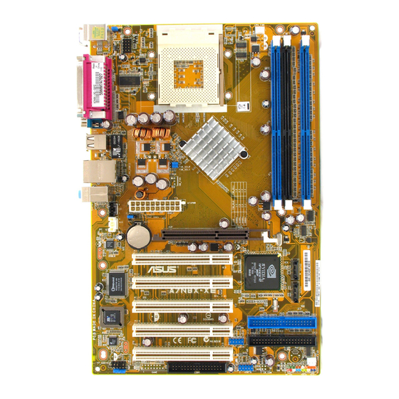
Page 16: Motherboard Layout
Accelerated Graphics Port (AGP Pro) RTL8201 AGP_WARN1 BIOS FPAUDIO1 PCI 1 nForce2 AUX1 Super Audio Chipset Codec PCI 2 SPDIF1 A7N8X ® PCI 3 CLRTC1 CR2032 3V Lithium Cell COM2 CMOS Power USB56 PCI 4 USBPWR_56 GAME1 ASUS ASIC PWR_LED1... -
Page 17: Before You Proceed
Central Processing Unit (CPU) The motherboard provides a Socket A (462) for CPU installation. AMD processors offer gigahertz speeds to support all the latest computing platforms and applications. The A7N8X supports Athlon ™ XP processors with “QuantiSpeed” data processing, large data caches, 3D enhancements and 400/333/266Mhz bus speeds. -
Page 18: System Memory
3. Firmly insert the DIMM into the socket until the retaining clips lock into place. Expansion slots The A7N8X motherboard has six (6) expansion slots. The following sub-sections describe the slots and the expansion cards that they support. 1.8.1 Configuring an expansion card Some expansion cards need an IRQ to operate. -
Page 19: Standard Interrupt Assignments
+1.5V AGP Pro/8X cards. Note the notches on the card golden fingers to ensure that they fit the AGP slot on your motherboard. AGP Card without Retention Notch ® A7N8X TOP VIEW 20-pin bay 28-pin bay Rib (inside slot) A7N8X Accelerated Graphics Port (AGP8X) ASUS A7N8X Motherboard... -
Page 20: Jumpers
A7N8X +5VSB (Default) A7N8X USB Device Wake Up 2. Central Processing Unit FSB (CPU_FSB) This jumper when set to 1-2 pins (default), enable support for Front Side Bus 400/333/266. When set to pins 2-3, it sets support for FSB 200 only. Support for FSB 400 is available to PCB 2.0 or later versions only. - Page 21 Normal Clear CMOS (Default) A7N8X Clear RTC RAM 4. Keyboard power (3-pin KBPWR1) This jumper allows you to enable or disable the keyboard wake-up feature. Set this jumper to pins 2-3 (+5VSB) if you wish to wake up the computer when you press a key on the keyboard (the default value is [Disabled]).
-
Page 22: Connectors
For UltraDMA/133/100/66 IDE devices, use an 80-conductor IDE cable. NOTE: Orient the red markings (usually zigzag) on the IDE ribbon cable to PIN 1. ® A7N8X PIN 1 A7N8X IDE Connectors 1-12 Chapter 1: Motherboard Information... - Page 23 ® A7N8X PIN 1 A7N8X Floppy Disk Drive Connector ATX power connectors (20-pin ATXPWR1) These connectors connect to an ATX 12V power supply. The plugs from the power supply are designed to fit these connectors in only one orientation. Find the proper orientation and push down firmly until the connectors completely fit.
- Page 24 ® A7N8X USB56 A7N8X USB 2.0 Header 5. GAME/MIDI connector (16-1 pin GAME1) This connector supports a GAME/MIDI module. If your package came with the optional USB 2.0/GAME module, connect the GAME/MIDI cable to this connector. The GAME/MIDI port on the module connects a joystick or a game pad for playing games, and MIDI devices for playing or editing audio files.
- Page 25 CHA_FAN1 ® A7N8X A7N8X 12-Volt Cooling Fan Power Do not forget to connect the fan cables to the fan connectors. Lack of sufficient air flow within the system may damage the motherboard components. These are not jumpers! DO NOT place jumper caps on the fan connectors! 7.
- Page 26 FPAUDIO1 ® A7N8X A7N8X Front Panel Audio Connector Hard disk connector (2-pin IDELED1) This 2-pin connector connects to the front panel HD LED and lights up on every read/write activity of any of the disc drives connected to the primary or secondary IDE slots.
- Page 27 This header supports a thermal sensor for the power supply. PWRTMP1 A7N8X ® PWRTMP Ground A7N8X Power Supply Thermal Connector 13. Digital Audio Connector (6 pin SPDIF1) (optional) This connector is for optional S/PDIF audio module that allows digital instead of analog sound input and output. SPDIF1 ®...
- Page 28 A7N8X IRTX (NC) IRRX A7N8X Infrared Connector 15. SMBus Connector (6-1 pin SMB1) This connector supports SMBus (System Management Bus) devices. SMBus devices communicate by means of the SMBus with an SMBus host and/or other SMBus devices. SMBus is a multi-device bus that permits multiple chips to connect to the same bus and enable each one to act as a master by initiating data transfer.
- Page 29 ATX Power SMI Lead Switch* Requires an ATX power supply. A7N8X System Panel Connectors • System Power LED Lead (3-1 pin PLED) This 3-1 pin connector connects to the system power LED. The LED lights up when you turn on the system power.
- Page 30 1-20 Chapter 1: Motherboard Information...
- Page 31 Chapter 2 This chapter gives information about the ASUS A7N8X Basic Input/Output System (BIOS).This chapter includes updating the BIOS using the ASUS AFLASH BIOS that is bundled with the support CD. ASUS A7N8X Motherboard...
-
Page 32: Managing And Updating Your Bios
A:\BIOSNAME.BIN C:\. • This motherboard uses the A7N8X BIOS file for 2Mb flash ROM. Another series model A7N8X Deluxe uses the BIOS file for a 4Mb flash ROM. Make sure to use the correct BIOS file on each model. •... -
Page 33: Updating Bios Procedures
BIOS. 2.1.2.1 Updating BIOS via Built-in AwardBIOS Flash Utility 1. Download the latest BIOS file from the ASUS website (see ASUS contact info on Page viii). Save the copy to a floppy disk. Write down the BIOS file name on a piece of paper. You need to type the exact BIOS file name at the Award BIOS Flash Utility. - Page 34 The program asks to save the previous BIOS to a separate file. Type a file name for the old bios and then press <Y>. The AWDFLASH program backs- up the file. AWDFLASH proceeds to check the new BIOS file and asks the user to program (flash) the new BIOS file to the motherboard.
- Page 35 The program asks if you want to save the previous BIOS. Select <Y> since it is advisable to back-up the original BIOS in case you need to reprogram it. 5. Follow steps 6 to 9 in “2.1.2.1 Updating BIOS via Built-in Award BIOS Flash Utility.” ASUS A7N8X Motherboard...
-
Page 36: Bios Setup Program
BIOS Setup program This motherboard supports a programmable FLASH ROM that you can update using the provided utility described in section “2.1 Managing and updating your BIOS.” Use the BIOS Setup program when you are installing a motherboard, reconfiguring your system, or prompted to “Run Setup”. This section explains how to configure your system using this utility. -
Page 37: Bios Menu Bar
Scrolls backward through the values for the highlighted field Page Up and + (plus) Scrolls forward through the values for the highlighted field <Enter> Brings up a selection menu for the highlighted field <F10> Saves changes and Exit ASUS A7N8X Motherboard... -
Page 38: General Help
General help In addition to the Item Specific Help window, the BIOS setup program also provides a General Help screen. You may launch this screen from any menu by simply pressing <F1> or the <Alt> + <H> combination. The General Help screen lists the legend keys and their corresponding functions. -
Page 39: Main Menu
Halt On [All Errors] This field sets the system to halt on errors according to the system functions specified in each option. Configuration options: [All Errors] [No Errors] [All, But Keyboard] [All , But Diskette] [All, But Disk/Key] ASUS A7N8X Motherboard... -
Page 40: Primary Master/Slave
2.3.1 Primary Master/Slave IDE HDD Auto-Detection [Press Enter] Press enter to automatically detect an IDE hard disk drive, if the hard drive is not already detected. In cases of undetected HDDs, pressing enter will detect the HDD and then open access to both the IDE Primary Master and Access Mode fields. IDE Primary Master/Slave [Auto] Select [Auto] to automatically detect an IDE hard disk drive. - Page 41 To make changes to this field, set the IDE Primary Master field to [Manual] and the Access Mode to [CHS]. Precomp This field displays the precompressed volumes on the hard disk, if any, in MB. 2-11 ASUS A7N8X Motherboard...
-
Page 42: Secondary Master/Slave
Landing Zone This field displays the drive’s maximum useable capacity as calculated by the BIOS based on the drive information you entered. Sector This field configures the number of sectors per track. Refer to the drive documentation to determine the correct value. To make changes to this field, set the Type field to [User Type HDD] and the Translation Method field to [Manual]. -
Page 43: Advanced Menu
PCI/VGA properties. IRQ resources are accessed from this menu. To access the menu bar items, press the up and down arrow keys and then press <enter> to view the desired menu. 2-13 ASUS A7N8X Motherboard... -
Page 44: Advanced Bios Features
2.4.1 Advanced BIOS Features Boot Virus Detection [Disabled] This field disables boot virus protection by default. Configuration options: [Enabled] [Disabled] CPU Level 1, Level 2 Cache [Enabled] These fields enables the CPU levels 1 and 2 cache by default. Configuration options: [Enabled] [Disabled] Quick Power On Self Test [Enabled] This field enables the power on test. -
Page 45: Advanced Chipset Features
CPU installed.The Front Side Bus (FSB) is equal to 2 times this field value. Frequency ranges are adjustable in increments of 1, 2, 3 and/or 5 MHz. Configuration options: [100 MHz]... [200 MHz] [204 MHz] [207 MHz] [211 MHz] 2-15 ASUS A7N8X Motherboard... - Page 46 CPU Frequency Multiple Setting [Auto] This field sets the frequency multiple between the CPU’s internal frequency (CPU speed) and external frequency. Set this field in conjunction with CPU Frequency (MHz) to match the speed of the CPU. CPU Frequency Multiple [5.0x] This field is available to unlocked processors only.
- Page 47 68, 69, 70, 71, 72, 73, 74, 75, 76, 77, 78, 79, 80, 81, 82, 83, 84, 85, 86, 87, 90, 93, 95, 97, 100MHz] System BIOS Cacheable [Disabled] This field establishes whether or not the BIOS is cacheable. Disabled by default. Configuration options: [Enabled] [Disabled] 2-17 ASUS A7N8X Motherboard...
-
Page 48: Integrated Peripherals
Video RAM Cacheable [Disabled] This field establishes whether or not the video RAM is cacheable. Disabled by default. Configuration options: [Enabled] [Disabled] DDR Reference Voltage [ 2.6V] This field sets the voltage limits for the voltage supplied to the DDR memory. Note that increasing voltage to the DDR can cause premature failure of system components. - Page 49 IRQ3] [3E8/IRQ4] [2E8/IRQ3] [Auto] Onboard Serial Port 2 [2F8/IRQ3] These fields set the addresses for onboard serial port 2. Serial Port 1 and Serial Port 2 must have different addresses. Configuration options: [Disabled] [3F8/IRQ4] [2F8/ IRQ3] [3E8/IRQ4] [2E8/IRQ3] [Auto] 2-19 ASUS A7N8X Motherboard...
-
Page 50: Power Management Setup
UART use as [COM Port] This field selects the device assignment for UART2 mode. The default is [COM Port]. Select [IR] to activate the next field, “UR2 Duplex Mode”. Configuration options: [IR] [COM Port] Onboard Parallel Port [378/IRQ7] This field sets the address of the onboard parallel port connector to 378/IRQ7 by default. - Page 51 This allows you to set whether or not to reboot the system after power interruptions. [Disabled] leaves your system off while [Enabled] reboots the system. [Previous State] sets the system back to the state it was before the power interruption. Configuration options: [Disabled] [Enabled] [Previous State] 2-21 ASUS A7N8X Motherboard...
-
Page 52: Pnp/Pci Configurations
Power On By PS/2 Mouse [Disabled] When set to [Enabled], this parameter allows you to use the PS/2 mouse to turn on the system. This feature requires an ATX power supply that provides at least 1A on the +5VSB lead. Configuration options: [Disabled] [Enabled] Power On By PS/2 Keyboard [Disabled] This parameter allows you to use specific keys on the keyboard to turn on the system. -
Page 53: Security Menu
A password is required for None System booting and entering into the CMOS setup and all items can be modified. Setup None A password is required to enter into the CMOS setup and all items can be modified. 2-23 ASUS A7N8X Motherboard... -
Page 54: Hardware Monitor Menu
Security Option [Setup] This field sets the security options. The default enables the setup option for security. Configuration options: [Setup] [System] Set Supervisor Password / Set User Password To set a password, highlight the appropriate field and press <Enter>. Type in a password then press <Enter>. - Page 55 N/A. Q-Fan Control [Disabled] This field allows you to enable or disable the ASUS Q-Fan feature that smartly adjusts the fan speeds for more efficient system operation. When this field is set to Fan Speed Ratio...
-
Page 56: Exit Menu
Exit Menu Exit & Save Changes Choose this option from the Exit menu to ensure the selected values are saved to the CMOS RAM. When selecting this option, a confirmation window appears. Select [Yes] to save changes and exit. The CMOS RAM is sustained by an onboard backup battery and stays on even when the PC is turned off. - Page 57 Chapter 3 This chapter helps you power up your system and install drivers and utilities that came with the support CD. ASUS A7N8X Motherboard...
-
Page 58: Chapter 3: Starting-Up
Install an operating system The A7N8X motherboard supports Windows 98SE/ME/2000/XP operating systems (OS). Always install the latest OS version and corresponding updates so you can maximize the features of your hardware. Because motherboard settings and hardware options vary, use the setup procedures presented in this chapter for general reference only. - Page 59 Click this item to load the installation wizard and install the Win98 QFE drivers. USB 2.0 Driver This item installs the Universal Serial Bus 2.0 (USB 2.0) driver. Some menu items appear only to specific operating system versions. ASUS A7N8X Motherboard...
-
Page 60: Asus Pc Probe
Browse Support CD Click this item to display the support CD contents. Technical support request form This item displays for print the ASUS technical support form. File List Click this item to view the file list of support software available.
Need help?
Do you have a question about the a7n8x and is the answer not in the manual?
Questions and answers