Table of Contents
Advertisement
Advertisement
Table of Contents

Related Manuals for Asus AT3IONT-I


Summary of Contents for Asus AT3IONT-I
- Page 1 AT3IONT-I DELUXE AT3IONT-I...
- Page 2 Product warranty or service will not be extended if: (1) the product is repaired, modified or altered, unless such repair, modification of alteration is authorized in writing by ASUS; or (2) the serial number of the product is defaced or missing.
-
Page 3: Table Of Contents
Contents Notices ... v Safety information ... vi About this guide ... vi AT3IONT-I Series specifications summary ... viii Chapter 1: Product introduction Before you proceed ... 1-1 Motherboard overview ... 1-2 1.2.1 Motherboard layout ... 1-2 1.2.2 Layout contents ... 1-2 Central Processing Unit (CPU) ... - Page 4 Control EuP [Disabled] ... 2-12 APM Configuration ... 2-12 Hardware Monitor ... 2-12 Boot Device Priority ... 2-13 Boot Settings Configuration ... 2-13 Security ... 2-14 ASUS EZ Flash 2 ... 2-15 Express Gate [Auto] ... 2-16 AI NET 2... 2-16...
-
Page 5: Federal Communications Commission Statement
Complying with the REACH (Registration, Evaluation, Authorisation, and Restriction of Chemicals) regulatory framework, we published the chemical substances in our products at ASUS REACH website at http://csr.asus.com/english/REACH.htm. DO NOT throw the motherboard in municipal waste. This product has been designed to enable proper reuse of parts and recycling. -
Page 6: How This Guide Is Organized
Safety information Electrical safety • To prevent electric shock hazard, disconnect the power cable from the electric outlet before relocating the system. • When adding or removing devices to or from the system, ensure that the power cables for the devices are unplugged before the signal cables are connected. If possible, disconnect all power cables from the existing system before you add a device. -
Page 7: Conventions Used In This Guide
Refer to the following sources for additional information and for product and software updates. ASUS websites The ASUS website provides updated information on ASUS hardware and software products. Refer to the ASUS contact information. Optional documentation Your product package may include optional documentation, such as warranty flyers, that may have been added by your dealer. -
Page 8: At3Iont-I Series Specifications Summary
- 2 x 240-pin DIMM sockets support maximum 4GB unbuffered non-ECC 1066/800 MHz DDR3 memory modules Refer to www.asus.com or this user manual for the Memory QVL (Qualified Vendors Lists). ** When you install a total memory of 4GB capacity or more, the operating system may only recognize less than 3GB. - Page 9 1 x DC port* 1 x Bluetooth adapter* 1 x WLAN antenna port* 2 x RCA out ports* * For AT3IONT-I DELUXE only 2 x USB 2.0/1.1 connector supports additional 4 USB 2.0/1.1 ports 1 x CPU fan connector 1 x Chassis fan connector...
-
Page 10: Chapter 1: Product Introduction
Before you start installing the motherboard, and hardware devices on it, check the items in your motherboard package. Refer to page ix for the list of accessories. • AT3IONT-I Series motherboards include AT3IONT-I and AT3IONT-I DELUXE two models. The package contents vary from models. -
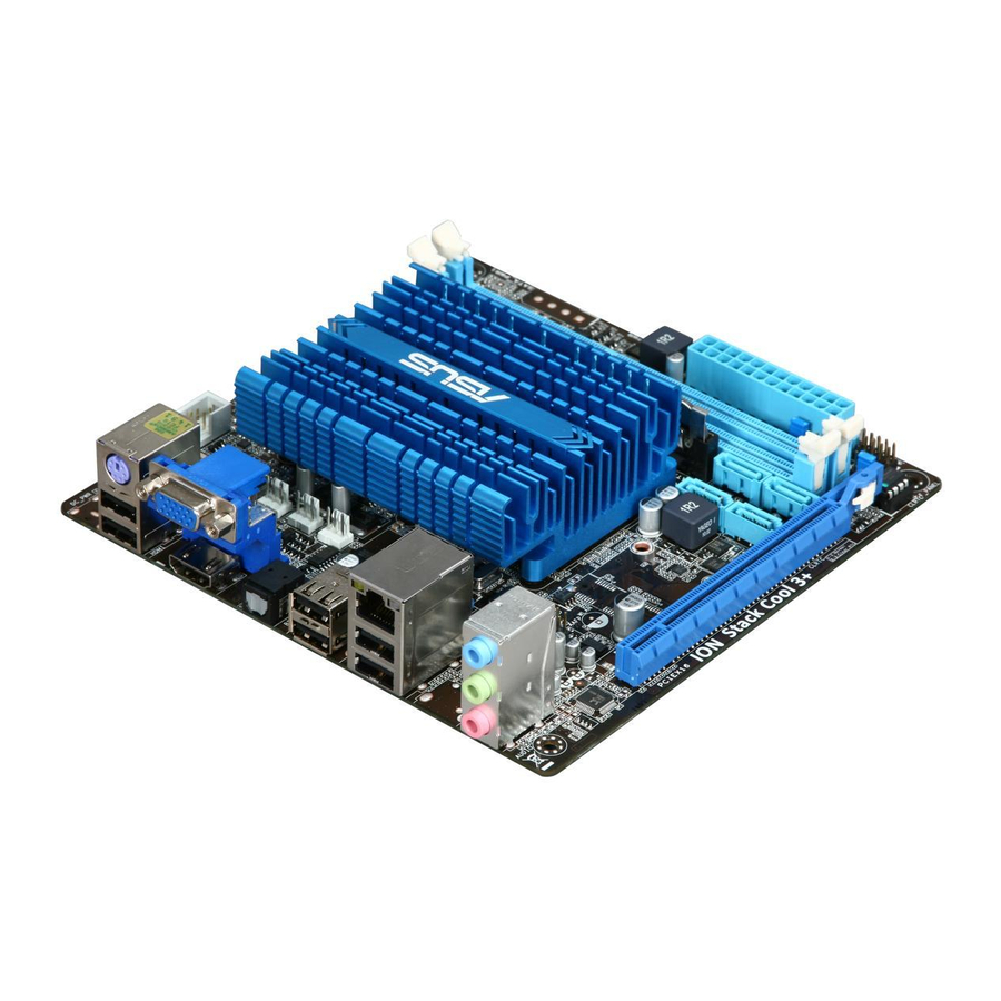
Page 11: Motherboard Overview
Motherboard overview 1.2.1 Motherboard layout ASUS AT3IONT-I Series motherboards include AT3IONT-I and AT3IONT-I DELUXE two models The layout varies with models. The layout illustrations in this user guide are for AT3IONT-I DELUXE only. Ensure that you install the motherboard into the chassis in the correct orientation. The edge with external ports goes to the rear part of the chassis. -
Page 12: Central Processing Unit (Cpu)
Overview The motherboard comes with two Double Data Rate 3 (DDR3) Dual Inline Memory Modules (DIMM) sockets. The figure illustrates the location of the DDR3 DIMM sockets: AT3IONT-I SERIES 240-pin DDR3 DIMM sockets Atom™ 330 processor and a ® Intel ®... -
Page 13: Memory Configurations
OS can be about 3GB or less. For effective use of memory, we recommend that you use a maximum of 3GB system memory. • This motherboard does not support DIMMs made up of 256 megabits (Mb) chips or less. AT3IONT-I Series Motherboard Qualified Vendors Lists (QVL) DDR3-1067 MHz capability Vendor Part No. - Page 14 DDR3-1333 MHz capability Vendor Part No. A-Data AD31333001GOU A-Data AD31333002GOU A-Data AD31333G002GMU Apacer 78.A1GC6.9L1 CORSAIR CM3X1024-1333C9DHX CORSAIR CM3X1024-1333C9 CORSAIR TR3X3G1333C9 G CORSAIR TR3X3G1333C9 G CORSAIR CM3X1024-1333C9DHX CORSAIR CM3X2048-1333C9DHX CORSAIR TW3X4G1333C9 G Crucial CT12864BA1339.8FF Crucial BL12864TA1336.8SFB1 Crucial CT25664BA1339.16FF Crucial BL25664ABA1336.16SFB1 Crucial BL25664BA1336.16SFB1 ELPIDA EBJ21UE8EDF0-DJ-F...
- Page 15 PSD31G13332H PATRIOT PSD31G13332 PATRIOT PSD32G13332H DDR3 1333MHz memory modules run at 1066MHz on AT3IONT-I Series motherboards. SS: Single-sided / DS: Double-sided DIMM support: • A*: Supports one module inserted into either slot as the single-channel memory configuration. • B*: Supports one pair of modules inserted into both the blue slots as one pair of dual-channel memory configuration.
-
Page 16: Expansion Slot
Expansion slot In the future, you may need to install expansion cards. The following sub-sections describe the slot and the expansion cards that it supports. Unplug the power cord before adding or removing expansion cards. Failure to do so may cause you physical injury and damage motherboard components. -
Page 17: Jumpers
CMOS RTC RAM data. The onboard button cell battery powers the RAM data in CMOS, which include system setup information such as system passwords. AT3IONT-I SERIES Clear RTC RAM To erase the RTC RAM: 1. Turn OFF the computer and unplug the power cord. - Page 18 WLAN antenna port (for AT3IONT-I DELUXE only) . This port Connects to the WLAN antenna. PS/2 Keyboard port (purple). This port is for a PS/2 keyboard. Video Graphics Adapter (VGA) port. This 15-pin port is for a VGA monitor or other VGA-compatible devices.
- Page 19 USB 2.0 ports 5 and 6. These two 4-pin Universal Serial Bus (USB) ports are available for connecting USB 2.0 devices. DC power port (for AT3IONT-I DELUXE only) . This port connects to an DC power adapter. ASUS AT3IONT-I Series...
-
Page 20: Internal Connectors
Serial ATA 1.5Gb/s specification. The data transfer rate of the Serial ATA 3Gb/s is faster than the standard parallel ATA (133 MB/s). AT3IONT-I SERIES SATA connectors • Install the Windows • If you intend to create a Serial ATA RAID set using these connectors, set the SATA Mode Select item in the BIOS to [RAID Mode]. - Page 21 SATA power connector (4-pin SATA_PWR1) (for AT3IONT-I DELUXE only) This connector is for SATA power cable. The power cable plug is designed to fit this connector in only one orientation. Find the proper orientation and push down firmly until the connector completely fit.
- Page 22 HD Audio or legacy AC`97 audio standard. Connect one end of the front panel audio I/O module cable to this connector. AT3IONT-I SERIES Analog front panel connector • We recommend that you connect a high-definition front panel audio module to this connector to avail of the motherboard’s high-definition audio capability.
-
Page 23: System Panel Connector
System panel connector (10-1 pin F_PANEL) This connector supports several chassis-mounted functions. AT3IONT-I SERIES System panel connector • System power LED (2-pin PLED) This 2-pin connector is for the system power LED. Connect the chassis power LED cable to this connector. The system power LED lights up when you turn on the system power, and blinks when the system is in sleep mode. - Page 24 The connector is for a serial (COM) port. Connect the serial port module cable to the connector, then install the module to a slot opening at the back of the system chassis. The serial port bracket (COM1) is purchased separately. AT3IONT-I SERIES Serial port (COM1) connector 1-15 COM1...
-
Page 25: Software Support
The contents of the Support DVD are subject to change at any time without notice. Visit the ASUS website at www.asus.com for updates. To run the Support DVD Place the Support DVD to the optical drive. -
Page 26: Asus Videosecurity
1.8.3 ASUS VideoSecurity ASUS VideoSecurity is a powerful monitoring and motion detection feature that enables users to keep an eye on their properties from a remote location via the Internet and a wide range of video capturing devices. System requirements Ensure that you have the following softwares and harwares installed on your computer before using the ASUS VideoSecurity. - Page 27 VideoSecurity Setting screen To launch the setting screen, click Click VideoSecurity. ASUS AT3IONT-I Series from the main screen. for the main screen to refer to the Help file for details on how to setup 1-18...
-
Page 28: Asus Home Theater Gate
Launching Home Theater Gate Install Home Theater Gate from the motherboard support DVD. To launch Home Theater Gate ,click Start > All Programs > ASUS > ASUS Home Theater Gate > ASUS Home Theater Gate 1.xx.xx. The Home Theater Gate main window appears. - Page 29 Resolution Music Video Photo Video player Music player • Visit the ASUS website at Visit the ASUS website at http://support.asus.com/download/download. aspx?SLanguage=en-us for the latest supported type. • Due to Window Blu-ray disc. ASUS AT3IONT-I Series Normal display under 1024 x 600 – 1920 x 1080...
- Page 30 Using the remote controller (for AT3IONT-I DELUXE only) Use the remote controller to launch the ASUS Home Theater Gate and start media applications. Connect the IR receiver to the USB 2.0 port 1 or 2 before using the remote controller.
-
Page 31: Chapter 2: Bios Information
BIOS in the future. Copy the original motherboard BIOS using the ASUS Update utility. 2.1.1 ASUS Update utility The ASUS Update is a utility that allows you to manage, save, and update the motherboard BIOS in Windows environment. ®... -
Page 32: Asus Ez Flash 2
Follow the onscreen instructions to complete the updating process. 2.1.2 ASUS EZ Flash 2 The ASUS EZ Flash 2 feature allows you to update the BIOS without using an OS-based utility. Before you start using this utility, download the latest BIOS file from the ASUS website at www.asus.com. -
Page 33: Recovering The Bios
2.1.3 ASUS CrashFree BIOS The ASUS CrashFree BIOS is an auto recovery tool that allows you to restore the BIOS file when it fails or gets corrupted during the updating process. You can restore a corrupted BIOS file using the motherboard support DVD or a removable device that contains the updated BIOS file. -
Page 34: Bios Setup Program
• The BIOS setup screens shown in this section are for reference purposes only, and may not exactly match what you see on your screen. • Visit the ASUS website at www.asus.com to download the latest BIOS file for this motherboard. -
Page 35: System Time [Xx:xx:xx]
Selects the DMA mode. Configuration options: [Auto] SMART Monitoring [Auto] Sets the Smart Monitoring, Analysis, and Reporting Technology. Configuration options: [Auto] [Disabled] [Enabled] 32Bit Data Transfer [Enabled] Enables or disables 32-bit data transfer. Configuration options: [Disabled] [Enabled] ASUS AT3IONT-I Series... -
Page 36: Storage Configuration
2.3.4 Storage Configuration The items in this menu allow you to set or change the configurations for the SATA devices installed in the system. Select an item then press <Enter> if you want to configure the item. OnChip S-ATA Controller [Enabled] Enables or disables the OnChip SATA controller. -
Page 37: Cpu Configuration
Memory Over Voltage [Auto] Manually set memory voltage or set to Auto for safe mode. Press <+>/<-> keys to adjust the value with an increment of 1.02000V. Configuration options: [Auto] [Min.=1.21000V] [Max.=2.47000V] ASUS AT3IONT-I Series Hyper Threading technology. Configuration options: ®... - Page 38 Chipset Over Voltage [Auto] Sets the chipset over voltage. Press <+>/<-> keys to adjust the value with an increment of 0.05000V. Configuration options: [Auto] [Min.=1.00000V] [Max.=1.10000V] Vcore Over Voltage [Auto] Sets the CPU Vcore over voltage. Press <+>/<-> keys to adjust the value with an increment of 0.05000V.
-
Page 39: Chipset
Allows you to enable or disable the boot ROM in the onboard LAN controller. This item appears only when the Onboard LAN item is set to Enabled. Configuration options: [Disabled] [Enabled] The following two items appear only on AT3IONT-I DELUXE motherboard. Onboard Bluetooth [Enabled] Allows you to enable or disable the onboard Bluetooth controller. -
Page 40: Usb Configuration
Onboard WLAN [Enabled] Allows you to enable or disable the onboard WLAN function. Configuration options: [Enabled] [Disabled] 2.4.5 USB Configuration The items in this menu allows you to change the USB-related features. Select an item then press <Enter> to display the configuration options. The Module Version and USB Devices Enabled items show the auto-detected values. -
Page 41: Pci Pnp
Allows you to enable or disable the Advanced Configuration and Power Interface (ACPI) support in the Application-Specific Integrated Circuit (ASIC). When set to Enabled, the ACPI APIC table pointer is included in the RSDT pointer list. Configuration options: [Disabled] [Enabled] ASUS AT3IONT-I Series BIOS SETUP UTILITY Boot Tools... -
Page 42: Control Eup [Disabled]
2.5.4 Control EuP [Disabled] Enables or disables the Energy Using Products (EuP) Ready function. When set to [Enabled], power for WOL, WO_USB, audio and onboard LEDs will be switched off at S5 state. Configuration options: [Disabled] [Enabled] 2.5.5 APM Configuration Restore on AC Power Loss [Power Off] When set to [Power Off], the system goes into off state after an AC power loss. -
Page 43: Boot Menu
Configuration options: [Removable Dev.] [Hard Drive] [ATAPI CD-ROM] [Disabled] • To select the boot device during system startup, press <F8> when ASUS Logo appears. • To access Windows •... -
Page 44: Security
Set this item to [Enabled] to use the ASUS MyLogo2 AddOn ROM Display Mode [Force BIOS] Sets the display mode for option ROM. Configuration options: [Force BIOS] [Keep Current] Bootup Num-Lock [On] Allows you to select the power-on state for the NumLock. Configuration options: [Off] [On] Wait For ‘F1’... -
Page 45: Tools Menu
2.7.1 ASUS EZ Flash 2 Allows you to run ASUS EZ Flash 2. When you press <Enter>, a confirmation message appears. Use the left/right arrow key to select between [Yes] or [No], then press <Enter> to confirm your choice. See section 2.1.2 ASUS EZ Flash 2 for details. -
Page 46: Express Gate [Auto]
2.7.2 Express Gate [Auto] Allows you to enable or disable the ASUS Express Gate feature. ASUS Express Gate is a unique instant-on environment that provides quick access to the Internet and Skype. Configuration options: [Enabled] [Disabled] [Auto] Enter OS Timer [10 Seconds] Sets countdown duration that the system waits at the Express Gate’s first screen... -
Page 47: Asus Contact Information
Online support ASUS COMPUTER INTERNATIONAL (America) Address Telephone Web site Technical Support Telephone Support fax Online support ASUS COMPUTER GmbH (Germany and Austria) Address Web site Online contact Technical Support Telephone (Component) Telephone (System/Notebook/Eee/LCD) Support Fax Online support * EUR 0.14/minute from a German fixed landline; EUR 0.42/minute from a mobile phone.
Need help?
Do you have a question about the AT3IONT-I and is the answer not in the manual?
Questions and answers