Table of Contents
Advertisement
Advertisement
Table of Contents

Related Manuals for Asus AT4NM10T-I


Summary of Contents for Asus AT4NM10T-I
- Page 1 AT4NM10T-I...
- Page 2 Product warranty or service will not be extended if: (1) the product is repaired, modified or altered, unless such repair, modification of alteration is authorized in writing by ASUS; or (2) the serial number of the product is defaced or missing.
-
Page 3: Table Of Contents
Contents Notices ......................v Safety information ..................vi About this guide ..................vii AT4NM10T-I specifications summary ............. viii Chapter 1: Product introduction Before you proceed ..............1-1 Motherboard overview ..............1-2 1.2.1 Motherboard layout ............1-2 1.2.2 Layout contents ............... 1-2 Central Processing Unit (CPU) ........... - Page 4 APM Configuration ............2-10 2.5.5 Hardware Monitor ............2-11 Boot menu .................. 2-12 2.6.1 Boot Device Priority ............2-12 2.6.2 Boot Settings Configuration .......... 2-12 2.6.3 Security ................. 2-13 Tools menu ................. 2-14 2.7.1 ASUS EZ Flash 2 ............2-14 Exit menu ..................2-15...
-
Page 5: Notices
This class B digital apparatus complies with Canadian ICES-003. ASUS Recycling/Takeback Services ASUS recycling and takeback programs come from our commitment to the highest standards for protecting our environment. We believe in providing solutions for you to be able to responsibly recycle our products, batteries, other components as well as the packaging materials. -
Page 6: Safety Information
Complying with the REACH (Registration, Evaluation, Authorisation, and Restriction of Chemicals) regulatory framework, we published the chemical substances in our products at ASUS REACH website at http://csr.asus.com/english/REACH.htm. DO NOT throw the motherboard in municipal waste. This product has been designed to enable proper reuse of parts and recycling. -
Page 7: About This Guide
Refer to the following sources for additional information and for product and software updates. ASUS websites The ASUS website provides updated information on ASUS hardware and software products. Refer to the ASUS contact information. Optional documentation Your product package may include optional documentation, such as warranty flyers, that may have been added by your dealer. -
Page 8: At4Nm10T-I Specifications Summary
Single channel memory architecture - 2 x 204-pin SO-DIMM sockets support maximum 4GB non-ECC DDR3 800 MHz memory modules Refer to www.asus.com or this user manual for the Memory QVL (Qualified Vendors Lists). ** When you install a total memory of 4GB capacity or more, the operating system may only recognize less than 3GB. - Page 9 AT4NM10T-I specifications summary Internal connectors 1 x USB 2.0/1.1 connector supports additional 2 USB 2.0/1.1 ports 1 x CPU fan connector 1 x Chassis fan connector 1 x Chassis intrusion connector 1 x TPM connector (optional) 1 x LPT connector...
-
Page 11: Chapter 1: Product Introduction
Chapter 1 Product introduction Thank you for buying an ASUS AT4NM10T-I motherboard! ® Before you start installing the motherboard, and hardware devices on it, check the items in your motherboard package. Refer to page ix for the list of accessories. -
Page 12: Motherboard Overview
Digital audio connector (4-1 pin SPDIF_OUT) 1-15 ® Keyboard/mouse power and USB device DDR3 DIMM sockets wake-up (3-pin PS2_USBPW1-6, 3-pin USBPW7-8) Chassis intrusion connector (4-1 pin CHASSIS) 1-12 Front panel audio connector (10-1 pin AAFP) 1-13 Internal speaker connector (4-pin SPEAKER) 1-12 ASUS AT4NM10T-I... -
Page 13: Central Processing Unit (Cpu)
Atom™ D425 processor and a specially ® designed CPU heatsink. Intel® Atom™ processor D425 AT4NM10T-I Intel® Atom™ processor D425 If you need to use an additional CPU fan, connect the CPU fan cable to the connector on the motherboard labeled CPU_FAN. CPU_FAN... -
Page 14: Memory Configurations
OS can be about 3GB or less. For effective use of memory, we recommend that you use a maximum of 3GB system memory. • This motherboard does not support DIMMs made up of 256 megabits (Mb) chips or less. AT4NM10T-I Motherboard Qualified Vendors Lists (QVL) DDR3-1066 MHz capability DIMM Vendor Part No. - Page 15 • B*: Supports one pair of modules inserted into both the slots. The 1333/1066 MHz memory modules run at 800 MHz on this motherboard. Visit the ASUS website at www.asus.com for the latest QVL. (continued on the next page) Chapter 1: Product introduction...
-
Page 16: Expansion Slot
Assign an IRQ to the card. Install the software drivers for the expansion card. 1.5.3 PCI Express x4 slots This motherboard supports PCI Express x4 network cards, SCSI cards, and other cards that comply with the PCI Express specifications. ASUS AT4NM10T-I... -
Page 17: Jumpers
Normal Clear RTC (Default) AT4NM10T-I Clear RTC RAM To erase the RTC RAM: 1. Turn OFF the computer and unplug the power cord. 2. Move the jumper cap from pins 1-2 (default) to pins 2-3. Keep the cap on pins 2-3 for about 5-10 seconds, then move the cap back to pins 1-2. - Page 18 USBPW78 +5VSB (Default) AT4NM10T-I USB Device Wake Up • The USB device wake-up feature requires a power supply that can provide 500mA on the +5VSB lead for each USB port; otherwise, the system would not power up. • The total current consumed must NOT exceed the power supply capability (+5VSB) whether under normal condition or in sleep mode.
-
Page 19: Connectors
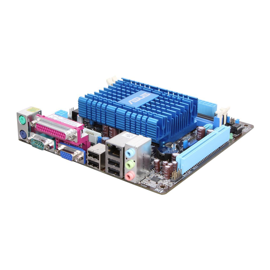
Connectors 1.7.1 Rear panel connectors PS/2 Mouse/Keyboard port (purple/green). This port is for a PS/2 mouse/keyboard. LAN (RJ-45) port. This port allows Gigabit connection to a Local Area Network (LAN) through a network hub. Refer to the table below for the LAN port LED indications. LAN port LED indications SPEED ACT/LINK... -
Page 20: Internal Connectors
• DO NOT forget to connect the 4-pin ATX +12V power plug. Otherwise, the system will not boot up. • If you are uncertain about the minimum power supply requirement for your system, refer to the Recommended Power Supply Wattage Calculator at http://support.asus. com/PowerSupplyCalculator/PSCalculator.aspx?SLanguage=en-us for details. ASUS AT4NM10T-I... - Page 21 Serial ATA 3.0 Gb/s signal cables. SATA3G_E2 SATA3G_2 SATA3G_E1 SATA3G_1 AT4NM10T-I SATA 3.0Gb/s connectors • Install the Windows XP Service Pack 3 or later version before using Serial ATA. ® • The SATA3G_E1/E2 (black) connectors are for data drives only. ATAPI device is not supported.
- Page 22 Remove the jumper caps only when you intend to use the chassis intrusion detection feature. CHASSIS AT4NM10T-I Chassis intrusion connector Internal speaker connector (4-pin SPEAKER) The 4-pin connector is for the chassis-mounted system warning speaker. The speaker allows you to hear system beeps and warnings.
- Page 23 CPU_FAN CHA_FAN AT4NM10T-I fan connectors Only 4-pin CPU_FAN and CHA_FAN connectors support the ASUS Q-FAN feature. Front panel audio connector (10-1 pin AAFP) This connector is for a chassis-mounted front panel audio I/O module that supports either HD Audio or legacy AC`97 audio standard. Connect one end of the front panel audio I/O module cable to this connector.
-
Page 24: System Panel Connector
F_PANEL PIN 1 HD_LED RESET AT4NM10T-I System panel connector • System power LED (2-pin PWR LED) This 2-pin connector is for the system power LED. Connect the chassis power LED cable to this connector. The system power LED lights up when you turn on the system power, and blinks when the system is in sleep mode. - Page 25 The serial port bracket (COM2) is purchased separately. COM2 PIN 1 AT4NM10T-I Serial port (COM2) connector Digital audio connector (4-1 pin SPDIF_OUT) This connector is for an additional Sony/Philips Digital Interface (S/PDIF) port. Connect the S/PDIF Out module cable to this connector, then install the module to a slot opening at the back of the system chassis.
- Page 26 The LPT (Line Printing Terminal) connector supports devices such as a printer. LPT standardizes as IEEE 1284, which is the parallel port interface on IBM PC-compatible computers. SLCT BUSY ACK# SLIN# INIT# ERR# STB# PIN 1 AT4NM10T-I Parallel Port Connector ASUS AT4NM10T-I 1-16...
-
Page 27: Software Support
Place the Support DVD to the optical drive. If Autorun is enabled in your computer, the DVD automatically displays the Specials screen which contains the unique feature of ASUS motherboard. Click Drivers, Utilities, Make Disk, Manual, and Contact tabs to display their respective menus. -
Page 28: Chapter 2: Bios Information
BIOS in the future. Copy the original motherboard BIOS using the ASUS Update utility. 2.1.1 ASUS Update utility The ASUS Update is a utility that allows you to manage, save, and update the motherboard BIOS in Windows environment. ®... -
Page 29: Asus Ez Flash 2
Follow the onscreen instructions to complete the updating process. 2.1.2 ASUS EZ Flash 2 The ASUS EZ Flash 2 feature allows you to update the BIOS without using an OS-based utility. Before you start using this utility, download the latest BIOS file from the ASUS website at www.asus.com. -
Page 30: Asus Crashfree Bios
2.1.3 ASUS CrashFree BIOS The ASUS CrashFree BIOS is an auto recovery tool that allows you to restore the BIOS file when it fails or gets corrupted during the updating process. You can restore a corrupted BIOS file using the motherboard support DVD or a removable device that contains the updated BIOS file. -
Page 31: Bios Setup Program
• The BIOS setup screens shown in this section are for reference purposes only, and may not exactly match what you see on your screen. • Visit the ASUS website at www.asus.com to download the latest BIOS file for this motherboard. -
Page 32: Main Menu
Main menu When you enter the BIOS Setup program, the Main menu screen appears, giving you an overview of the basic system information. AT4NM10T-I BIOS Setup Version 0306 Main Advanced Power Boot Tools Exit Use [ENTER], [TAB] or System Time... -
Page 33: Storage Configuration
This menu gives you an overview of the general system specifications. The BIOS automatically detects the items in this menu. BIOS Information Displays the auto-detected BIOS information. Processor Displays the auto-detected CPU specification. System Memory Displays the auto-detected system memory. ASUS AT4NM10T-I... -
Page 34: Advanced Menu
The Advanced menu items allow you to change the settings for the CPU and other system devices. Take caution when changing the settings of the Advanced menu items. Incorrect field values can cause the system to malfunction. AT4NM10T-I BIOS Setup Version 0306 Main Advanced... -
Page 35: Onboard Devices Configuration
Configuration options: [SSP] [EPP] [ECP] [EPP + ECP] ECP Mode DMA Channel [DMA3] Appears only when the Parallel Port Mode is set to [ECP]. This item allows you to set the Parallel Port ECP DMA. Configuration options: [DMA0] [DMA1] [DMA3] ASUS AT4NM10T-I... -
Page 36: Usb Configuration
2.4.4 USB Configuration The items in this menu allows you to change the USB-related features. Select an item then press <Enter> to display the configuration options. The Module Version and USB Devices Enabled items show the auto-detected values. If no USB device is detected, the item shows None. -
Page 37: Power Menu
Power menu The Power menu items allow you to change the settings for the Advanced Power Management (APM). Select an item then press <Enter> to display the configuration options. AT4NM10T-I BIOS Setup Version 0306 Main Advanced Power Boot Tools Exit... -
Page 38: Hardware Monitor
N/A. Select Ignored if you do not wish to display the detected speed. CPU/Chassis Q-Fan Function [Enabled] Enables or disables the ASUS Q-Fan feature that smartly adjusts the CPU fan speeds for more efficient system operation. Configuration options: [Disabled] [Enabled] VCORE Voltage, 3.3V Voltage, 5V Voltage, 12V Voltage [xxxV] or [Ignored]... -
Page 39: Boot Menu
Configuration options: [Removable Dev.] [Hard Drive] [ATAPI CD-ROM] [Disabled] • To select the boot device during system startup, press <F8> when ASUS Logo appears. • To access Windows OS in Safe Mode, do any of the following: ®... -
Page 40: Security
2.6.3 Security The Security menu items allow you to change the system security settings. Select an item then press <Enter> to display the configuration options. Change Supervisor Password Select this item to set or change the supervisor password. The Supervisor Password item on top of the screen shows the default Not Installed. -
Page 41: Tools Menu
2.7.1 ASUS EZ Flash 2 Allows you to run ASUS EZ Flash 2. When you press <Enter>, a confirmation message appears. Use the left/right arrow key to select between [Yes] or [No], then press <Enter> to confirm your choice. See section 2.1.2 ASUS EZ Flash 2 for details. -
Page 42: Exit Menu
Exit menu The Exit menu items allow you to load the optimal or failsafe default values for the BIOS items, and save or discard your changes to the BIOS items. AT4NM10T-I BIOS Setup Version 0306 Main Advanced Power Boot Tools... -
Page 43: Asus Contact Information
+1-510-739-3777 +1-510-608-4555 Web site usa.asus.com Technical Support Telephone +1-812-282-2787 Support fax +1-812-284-0883 Online support support.asus.com ASUS COMPUTER GmbH (Germany and Austria) Address Harkort Str. 21-23, D-40880 Ratingen, Germany +49-2102-959911 Web site www.asus.de Online contact www.asus.de/sales Technical Support Telephone (Component) +49-1805-010923*...
Need help?
Do you have a question about the AT4NM10T-I and is the answer not in the manual?
Questions and answers