Sign In
Upload
Download
Table of Contents
Contents
Add to my manuals
Delete from my manuals
Share
URL of this page:
HTML Link:
Bookmark this page
Add
Manual will be automatically added to "My Manuals"
Print this page
×
Bookmark added
×
Added to my manuals
Manuals
Brands
Cisco Manuals
Switch
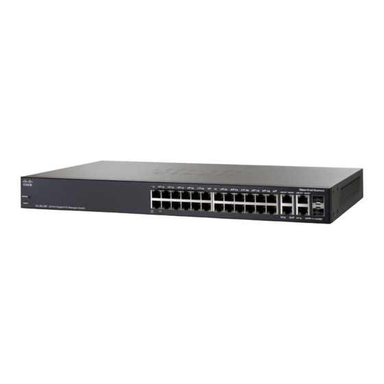
SLM224G4S
Administration manual
Cisco SLM224G4S Administration Manual
Slm smart switches
Hide thumbs
Also See for SLM224G4S
:
User manual
(56 pages)
1
2
Table Of Contents
3
4
5
6
7
8
9
10
11
12
13
14
15
16
17
18
19
20
21
22
23
24
25
26
27
28
29
30
31
32
33
34
35
36
37
38
39
40
41
42
43
44
45
46
47
48
49
50
51
52
53
54
55
56
57
58
59
60
61
62
63
64
65
66
67
68
69
70
71
72
73
74
75
76
77
78
79
80
81
82
83
84
85
86
87
88
89
90
91
page
of
91
Go
/
91
Contents
Table of Contents
Bookmarks
Table of Contents
Table of Contents
Chapter 1: Getting Started
Starting the Application
The about Window
Setup
Summary
Network Settings
Time
Chapter 2: Port Management
Port Settings
Link Aggregation
Lacp
Poe Power Settings
Chapter 3: VLAN Management
Create VLAN
Port Setting
Port to VLAN
VLAN to Port
Chapter 4: Statistics
Interface Statistics
Chapter 5: Security
802.1X Settings
Port Security
IP Access List
Storm Control
Radius
Chapter 6: Quality of Service
Cos Settings
Queue Settings
DSCP Settings
Basic Mode
Chapter 7: Spanning Tree
STP Status
Global STP
STP Port Settings
Chapter 8: Multicast
IGMP Snooping
Bridge Multicast
Bridge Multicast Forward All
Chapter 9: Admin
User Authentication
Static Address
Dynamic Address
Port Mirroring
Save Configuration
Firmware Upgrade
Reboot
Factory Default
Logging
Memory Logs
Flash Logs
Defining Bonjour
Advertisement
Quick Links
1
Starting the Application
2
Chapter 1: Getting Started
3
Setup
4
Network Settings
Download this manual
See also:
User Manual
ADMINISTRATION
GUIDE
Cisco Small Business
SLM Smart Switches
Table of
Contents
Previous
Page
Next
Page
1
2
3
4
5
Advertisement
Table of Contents
Need help?
Do you have a question about the SLM224G4S and is the answer not in the manual?
Ask a question
Questions and answers
Related Manuals for Cisco SLM224G4S
Network Router Cisco SLM2024 User Manual
Business series smart gigabit ethernet switch (56 pages)
Switch Cisco Gigabit Smart Switch with Resilient Clustering Technology and PoE SLM224G4PS User Manual
24-port or 48-port 10/100 + 4-port gigabit smart switch with resilient clustering technology and poe (78 pages)
Switch Cisco SLM2005 User Manual
5-port and 8-port 10/100/1000 gigabit smart switch with pd and ac power business series (32 pages)
Switch Cisco SLM248P Quick Start Manual
Smart switch (13 pages)
Network Router Cisco SLM248P Datasheet
48-port 10/100 + 2-port gigabit smart switch: sfps/poe (5 pages)
Switch Cisco SLM2005 Datasheet
5-port gigabit smart switch: pd/ac power (4 pages)
Switch Cisco SLM2008 Datasheet
8-port gigabit smart switch: pd/ac power (4 pages)
Switch Cisco SLM2008PT-NA Administration Manual
Cisco small business 8-port gigabit smart switch with pd and ac power (66 pages)
Switch Cisco SLM2024 Datasheet
Cisco slm2024 24-port gigabit smart switch (5 pages)
Switch Cisco SLM2024 - Small Business Smart Switch Administration Manual
Slm smart switches (91 pages)
Switch Cisco SLM224P - Small Business Smart Switch Administration Manual
Slm smart switches (91 pages)
Switch Cisco SLM2048 - Small Business Smart Switch Administration Manual
Slm smart switches (91 pages)
Switch Cisco SLM224G - Small Business Smart Switch Administration Manual
Slm smart switches (91 pages)
Switch Cisco SLM2024PT-NA Datasheet
200 series switches cisco small business (11 pages)
Switch Cisco SLM248G - Small Business Smart Switch Administration Manual
Slm smart switches (91 pages)
Switch Cisco Linksys SLM224G45 User Manual
24-port or 48-port 10/100 + 4-port 10/100/1000 gigabit stackable smart switch with 2 combo sfps (68 pages)
This manual is also suitable for:
Slm2005 - small business smart switch
Slm2024
Slm2048
Slm224g
Slm224p
Slm248g
...
Show all
Slm248g4ps - small business smart switch
Slm248g4s - small business smart switch
Slm248p
Table of Contents
Print
Rename the bookmark
Delete bookmark?
Delete from my manuals?
Login
Sign In
OR
Sign in with Facebook
Sign in with Google
Upload manual
Upload from disk
Upload from URL


Need help?
Do you have a question about the SLM224G4S and is the answer not in the manual?
Questions and answers