PRESONUS HP4 User Manual
Smart compressor headphone distribution amplifier 3 band parametric equalizer
Hide thumbs
Also See for HP4:
- User manual (28 pages) ,
- Owner's manual (20 pages) ,
- Owner's manual (27 pages)
Advertisement
Quick Links
Download this manual
See also:
Owner's Manual
COMP16
S M A R T
C O M P R E S S O R
HP4
H E A D P H O N E
D I S T R I B U T I O N
A M P L I F I E R
EQ3B
3 B A N D P A R A M E T R I C E Q A L I Z E R
USERS MANUAL
Version 1.0
PreSonus Audio Electronics
Advertisement

Related Manuals for PRESONUS HP4


Summary of Contents for PRESONUS HP4
- Page 1 A M P L I F I E R EQ3B 3 B A N D P A R A M E T R I C E Q A L I Z E R USERS MANUAL Version 1.0 PreSonus Audio Electronics...
- Page 3 A M P L I F I E R EQ3B 3 B A N D P A R A M E T R I C E Q A L I Z E R USERS MANUAL Version 1.0 2003, PreSonus Audio Electronics, Incorporated. All rights reserved.
- Page 4 Number and instructions of where to return the unit for service. All inquiries must be accompanied by a description of the problem. All authorized returns must be sent to the PreSonus repair facility postage prepaid, insured and properly packaged. PreSonus reserves the right to update any unit returned for repair.
- Page 5 2.1 A Word About Compression 2.2 Front/Back Panel Basic Layout 2.3 Presets 2.4 Application Guide EQ3B 3.1 Front/Back Panel Basic Layout 3.2 Application Guide 4.1 Front/Back Panel Basic Layout 4.2 Application Guide Technical Specifications 5.1 COMP16 Specifications 5.2 EQ3B Specifications 5.3 HP4 Specifications...
- Page 6 We value your comments and suggestions. Please pay close attention to how you connect your PreSonus Product to your system. Improper grounding is the most common cause of noise problems in both live and studio applications. We suggest you look at the application guides which are part of this manual to insure optimum operation.
- Page 7 PRESONUS 2 . 1 W O R D A B O U T C O M P R E S S I O N Punch, apparent loudness, presence… just three of many terms used to describe the effects of compression/ limiting.
- Page 8 PRESONUS 10:1 are considered hard limiting. Limiting refers to the point at which the signal is restrained from going any louder at the output. The level of input signal at which the output is reduced is determined by the compression threshold. As the compression threshold is lowered, more and more of the input signal is compressed (assuming a nominal input signal level).
- Page 9 PRESONUS 2 . 2 C O M P 1 6 F R O N T P A N E L B A S I C L A Y O U T The front panel on the COMP16 is divided into three sections.
- Page 10 PRESONUS compressor lowers the output level during gain reduction, the overall signal level is lowered, requiring the user to ‘ makeup’ the gain thereby restoring the original signal level. Output to Meter This button selects the function of the Output/Gain Reduction meter.
- Page 11 PRESONUS Input The input jack accepts balanced/unbalanced tip-sleeve or tip-ring-sleeve connectors or XLR connectors. The input can handle up to +22dBu unbalanced levels. Output The output jack accepts (balanced/unbalanced) tip-sleeve, tip-ring-sleeve or XLR connectors. The output will deliver up to +22dBu in signal level unbalanced.
- Page 12 PRESONUS -3.3dB 2.8:1 0.002mS 38mS SCREAMER - For loud vocals. Fairly hard compression for a vocalist who is ‘ on’ and ‘ off’ the microphone a lot. It puts the voice ‘ in your face’ . Threshold Ratio Attack Release -1.1dB...
- Page 13 PRESONUS Threshold Ratio Attack Release -4.4dB 2.6:1 45.7mS 189mS ACOUSTIC GUITAR - This setting accentuates the attack of the acoustic guitar and helps maintain an even signal level keeping the acoustic guitar from disappearing in the track. Threshold Ratio Attack Release -6.3dB...
- Page 14 PRESONUS ORCHESTRAL - Use this setting for string ‘ pads’ and other types of synthesized orchestra parts. It will decrease the overall dynamic range for easier placement in the mix. Threshold Ratio Attack Release 3.3dB 2.5:1 1.8mS 50mS Limit MONO LIMITER - Just as the name implies. A hard limiter setting (brick wall) ideal for controlling level to the 2 track mixdown deck or Mono output.
- Page 15 PRESONUS PUMP - Make the COMP16 ‘ pump up the prime’ . A setting for making the compressor pump in a desirable way. This effect is good for snare drum to increase the length of the transient by bringing the signal up after the initial spike. Very contemporary.
- Page 16 PRESONUS 2 . 4 A P P L I C A T I O N G U I D E Q U I C K S T A R T 1. Connect your COMP16 using one input jack (TS, TRS, or XLR) and one or more of the output jacks(TS, TRS, or XLR).
- Page 17 PRESONUS B A S I C C O N N E C T I O N S The COMP16 can be hooked to another processor, such as the EQ3B or TubePre in a live or studio environment. Please note that a microphone can not be plugged directly into the COMP16.
- Page 18 PRESONUS B A S I C O P E R A T I N G P R O C E D U R E S Setting Compression Amount Your COMP16 was designed with a fixed threshold mode of operation. This differs from other compressors in the fact that there is no threshold control.
- Page 19 PRESONUS 3 . 1 E Q 3 B F R O N T P A N E L B A S I C L A Y O U T The front panel on the EQ3B is divided into three sections. These...
- Page 20 PRESONUS Figure1 Bypass If the BYPASS button is not pushed in, the EQ3B is processing the signal (equalizing). Pushed in, the EQ3B is no longer equalizing the signal. 80Hz The 80Hz button is a low end roll off filter. When pushed in, the 80Hz button causes all frequencies below 80Hz to be attenuated (dropped) by 12dB.
- Page 21 PRESONUS Input The input jack accepts balanced/unbalanced tip-sleeve or tip-ring-sleeve connectors or XLR connectors. The input can handle up to +24dBu unbalanced levels. Output The output jack accepts (balanced/unbalanced) tip-sleeve, tip-ring-sleeve or XLR connectors. The output will deliver up to +24dBu in signal level unbalanced.
- Page 22 PRESONUS connector jack. This end of the cable plugs into the insert jack on the mixer channel. The other ends of the cable plug into the input and output of the EQ3B. If the EQ3B does not work immediately, you may want to try changing the jacks that are plugged into the...
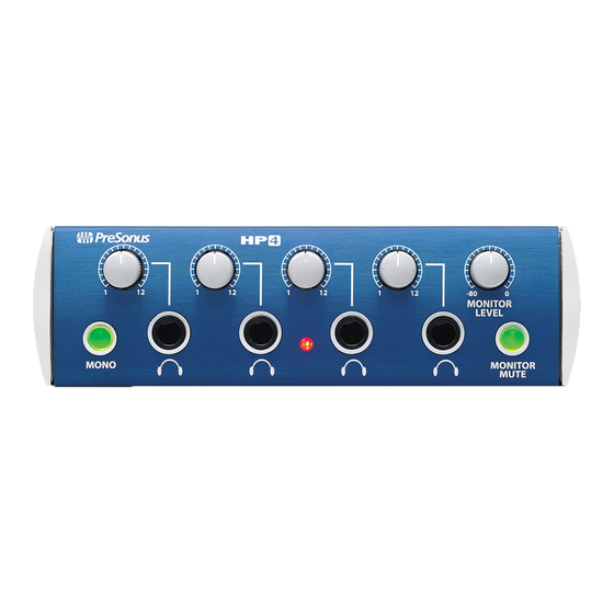
- Page 23 1 and then bring the volume up. Monitor Level The monitor level knob corresponds to the output volume of the output on the back of the HP4. The level can be muted by pressing the Monitor Mute button. Mono When the Mono button is pushed in, each input will be summed together on each output.
- Page 24 PRESONUS is not pushed in, the left output will have the left input signal and vice-versa. Monitor Mute The monitor mute button is handy when you are only using the headphone outputs and don’ t want to use the Master Outputs.
- Page 25 Care should be taken that the headphone output level of the console/mixer is not set to high. Setting the output level to the HP4 too loud, could cause the unit to distort. The monitor outputs are designed to be connected to the power amp of your studio speakers, to the inputs of self amplified speakers, or to another HP4.
- Page 26 PRESONU S 5 . 1 C O M P 1 6 S P E C I F I C A T I O N S Number of Channels........... 1 Dynamic Range ..........>115dB Signal to Noise Ratio .......... >95dB Headroom............+22dBu Frequency Response ......
- Page 27 PRESONUS 5 . 2 E Q 3 B S P E C I F I C A T I O N S Number of Channels........... 1 Dynamic Range ..........>115dB Signal to Noise Ratio .......... >95dB Headroom............+22dBu Frequency Response ......10Hz to 50kHz XLR Input Impedance ........
- Page 28 PRESONUS 5 . 3 H P 4 S P E C I F I C A T I O N S Number of Channels........1 in 5 out Dynamic Range ..........>115dB Signal to Noise Ratio .......... >95dB Headroom............+22dBu Frequency Response ......10Hz to 50kHz Input Impedance..........
Need help?
Do you have a question about the HP4 and is the answer not in the manual?
Questions and answers