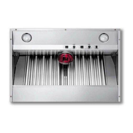
Viking VBCV4238 Installation Instructions Manual
Built-in 18” h. hoods (indoor and outdoor models)
Hide thumbs
Also See for VBCV4238:
- Brochure & specs (44 pages) ,
- Use and care manual (10 pages) ,
- Installation instructions manual (8 pages)
Advertisement
Quick Links
Download this manual
See also:
Use and Care Manual
Advertisement

Summary of Contents for Viking VBCV4238
- Page 1 Viking Installation Guide Viking Range Corporation 111 Front Street Greenwood, Mississippi 38930 USA (662) 455-1200 For product information, call 1-888-VIKING1 (845-4641) or visit the Viking Web site at vikingrange.com Built-In 18” H. Hoods (Indoor and Outdoor Models) F1571S EN (041408J)
- Page 2 60”W. 1200 int./1200 ext./1500 ext. 11.5/8.8/9.5 for use with Viking Range hoods. Use of any non-Viking Range WARNING - TO REDUCE THE RISK OF INJURY TO ventilator kit will void the hood warranty. PERSONS IN THE EVENT OF A RANGETOP GREASE...
-
Page 3: Wall Installation
HEIGHT OF INDOOR HOOD PREPARING FOR HOOD INSTALLATION The bottom of the hood should be 30” (76.2 cm) min. to 36” (91.4 cm) max. above the countertop. This would Plan where the ductwork will be located. See pages 9-12 for rough-in dimensions. Install proper-sized duct work, and typically result in the bottom of the hood being 66”... -
Page 4: Installing Hood Canopy
INSTALLING HOOD CANOPY INSTALLING ROUGH-IN PLATE AND CONNECTING DUCT - INTERNAL POWER Wall Hoods (Also see instructions supplied with ventilator kit) (VBCV/VICV Custom Ventilator Kits Only) 1. Attach rough-in plate to studs in the inside, top of hood with four (4) #10-24 nuts provided. 30”... - Page 5 INSTALLING THE VENTILATORS INSTALLING ROUGH-IN PLATE AND CONNECTING DUCT -EXTERNAL POWER VIV300 or VIV600 - Interior-Power Ventilator Kit (300 or 600 CFM) (Also see instructions supplied with ventilator kit) (also see instructions supplied with ventilator kit) 1. Make sure barrel nuts and wing nut are engaged halfway onto threaded stud. 1.
-
Page 6: Roof Installation
ROOF INSTALLATION ROOF CUTOUT WALL INSTALLATION WALL CUTOUT EXTERIOR-POWER VENTILATOR EXTERIOR-POWER VENTILATOR 20 3 4” (52.7 cm) 25” (63.5 cm) VEV900-Exterior Power Ventilator Kit (900CFM) VEV900-Exterior-Power Ventilator Kit (900CFM) 4” 1. Choose a position on the outside wall. Min. 24” (61.0 (also see instructions supplied with ventilator kit) 2”... - Page 7 WALL CUTOUT ROOF INSTALLATION ROOF CUTOUT WALL INSTALLATION 1 /4” (3.2 EXTERIOR-POWER VENTILATOR EXTERIOR-POWER VENTILATOR cm) dia. hole Exterior Power Ventilator Exterior Power Ventilator Kit 1. Choose a position on the outside wall. Min. 24” (61.0 cm (also see instructions supplied with ventilator kit) 3”...
- Page 8 EXTERIOR VENTILATOR DIMENSIONS WALL HOOD DIMENSIONS Transition VEV1200 (Indoor/Outdoor VWH Models) VIV1200 Only VEV1500 VEV900 Opening for wiring 9” (22.9 cm) 12” 1 1/2” 1” (2.54 cm) 10” Dia. (30.5 cm) (3.81 cm) 1 1/2” (3.81 cm) 7/8” (2.22 cm) ”...
- Page 9 BUILT-IN CUSTOM VENTILATOR SYSTEM DIMENSIONS Transition (VBCV Models) VIV1200 Only 9” (22.9 cm) 18 1/2” 1 1/2” 1” (2.54 cm) 1 1/2” (50 cm) (3.81 cm) (3.81 cm) 7/8” 9 3/8” 8 3/16” 5 15/16” ( 15.1cm (23.8 cm) 5 /8” (2.22 cm) (1.6 cm) (20.7 cm)
- Page 10 18 1/2” 5 1/2” (14.0 cm) (50.0 cm) 5 1/2” 8 1/4” 9 3/8” (14.0 cm) (20.9 cm) 18 3/4” (47.6 cm) (23.8 cm) 6” 1 1/16” (2.7 cm) 5/8” (1.6 cm) 9 3 /8” 8 1/4” (15.2 cm) 8 3/8” (20.9 cm) (21.3 cm) (23.8 cm)
- Page 11 BUILT-IN CUSTOM VENTILATOR SYSTEM DIMENSIONS 18 3/4”(47.6 cm) (VICV Models) Transition 7/8” VIV1200 Only 8 1/4” (2.2 cm) (21.0 cm) 1 1/2” 1 1/2” 5 3/4” 1” 5 3/4” 6” (3.8 cm) 9” (14.6 cm) 8 3/8” (2.5 cm) (3.8 cm) (14.6 cm) 11/16”...


