Table of Contents
Advertisement
Quick Links
Q
S
UICK
TART
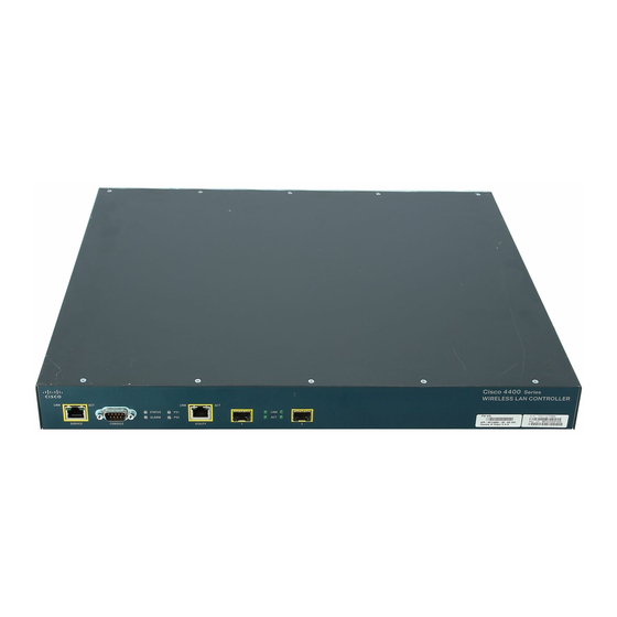
Cisco 4400 Series Wireless LAN Controllers
INCLUDING LICENSE AND WARRANTY
1
About this Guide
2
Introduction to the Controller
3
Unpacking and Preparing the Controller for Operation
4
Using the Startup Wizard
5
Obtaining Documentation and Submitting a Service Request
6
Cisco 90-Day Limited Hardware Warranty Terms
1
About this Guide
This guide is designed to help you install and minimally configure your Cisco 4400 Series
Wireless LAN Controller. This guide covers the following controller models: 4402-25,
4402-50, 4404-25, 4404-50, and 4404-100.
G
UIDE
Advertisement
Table of Contents

Related Manuals for Cisco 4404 - Wireless LAN Controller


Summary of Contents for Cisco 4404 - Wireless LAN Controller
- Page 1 Cisco 90-Day Limited Hardware Warranty Terms About this Guide This guide is designed to help you install and minimally configure your Cisco 4400 Series Wireless LAN Controller. This guide covers the following controller models: 4402-25, 4402-50, 4404-25, 4404-50, and 4404-100.
-
Page 2: Fcc Safety Compliance Statement
• When multiple Cisco 4400 series controllers are mounted in an equipment rack, be sure that the power source is sufficiently rated to safely run all the equipment in the rack. -
Page 3: Statement 371-Power Cable And Ac Adapter
Ethernet or IP infrastructure, thereby protecting existing network investments while providing the best in class wireless services. A core component of the Cisco unified wireless solution, these controllers deliver wireless security, intrusion detection, radio management, quality of service (QoS), and mobility across an entire enterprise. - Page 4 Ethernet distribution system ports, each of which is capable of managing up to 48 access points. However, Cisco recommends no more than 25 access points per port due to bandwidth constraints. The 4402-25 and 4402-50 models allow a total of 25 or 50 access points to join the controller.
- Page 5 Figure 2 shows the back panel layout with a power supply unit installed in power supply slot 2. Figure 2 Back Panel Layout VPN termination module Slot 1 Slot 2 power supply power receptacle VPN termination module slot 0 Slot 2 power supply switch Power supply slot 1 Slot 2 power supply LED Checking the Controller LEDs...
-
Page 6: Package Contents
Return all packing materials to the shipping container and save it. Ensure that all items listed in the “Package Contents” section are included in the shipment. Step 3 Check each item for damage. If any item is damaged or missing, notify your authorized Cisco sales representative. Package Contents Each access point package contains the following items: •... -
Page 7: Required Tools And Information
• Local TFTP server (required for downloading operating system software updates). Cisco uses an integral TFTP server. This means that third-party TFTP servers cannot run on the same workstation as the Cisco WCS because Cisco WCS and third-party TFTP servers use the same communication port. -
Page 8: Choosing A Physical Location
• A virtual gateway IP address (a fictitious, unassigned IP address, such as 1.1.1.1, used by all Cisco wireless LAN controller Layer 3 security and mobility managers). • A Cisco wireless LAN controller mobility group name, if required. • An 802.11 network name (SSID) for WLAN 1. This is the default SSID that the access points use when they join with the controller. -
Page 9: Installing The Chassis
• Install the SFP modules as described in the 1000BASE-SX, 1000BASE-LX, and 1000BASE-T SFP Module Quick Start Guide. • If you have purchased an extra power supply module or enhanced security modules, refer to the Cisco 4400 Series Power Supply Quick Start Guide for information about installing these devices. - Page 10 Warning This unit might have more than one power supply connection. All connections must be removed to de-energize the unit. Statement 1028 Connecting the Controller’s Console Port Before you can configure the controller for basic operations, you need to connect it to a PC that uses a VT-100 terminal emulator (such as HyperTerminal, ProComm, Minicom, or Tip).
- Page 11 Bootloader 3.4.0.0. (Feb 2 2006 - 19:14:47) Motorola PowerPC ProcessorID=00000000 Rev. PVR=80200020 Cisco Systems INC., 4400 Wireless LAN Switch Board CPU: 833 MHz CCB: 333 MHz DDR: 166 MHz LBC: 41 MHz L1 D-cache 32KB, L1 I-cache 32KB enabled.
- Page 12 The rest of the is process takes two to three minutes. Do not reboot the controller until the Step 4 user login prompt appears. Cisco is a trademark of Cisco Systems, Inc. Software Copyright Cisco Systems, Inc. All rights reserved. Cisco AireOS Version 3.4.0.0...
- Page 13 Initializing Serial Services: ok Initializing Network Services: ok Starting ARP Services: ok Starting Trap Manager: ok Starting Network Interface Management Services: ok policyBuildDefaultConfigData: Setting default LWAPP MODE to L3 policySysReadConfig: policySystemLwappModeSet(L3) Starting System Services: ok Starting Fast Path Hardware Acceleration: ok Starting Switching Services: ok Starting QoS Services: ok Starting Policy Manager: ok...
-
Page 14: Using The Startup Wizard
Starting Management Services: Web Server: ok CLI: ok Secure Web: ok Step 5 If the controller passes the power-on self test, the bootup script runs the Startup Wizard, which prompts you for basic configuration inputs. Using the Startup Wizard Before you can use the startup wizard, you must obtain the information discussed in the “Required Tools and Information”... - Page 15 Enter the IP address, netmask, default router IP address, and optional VLAN identifier (a valid Step 5 VLAN identifier or 0 for an untagged VLAN) for the management interface. The VLAN identifier should be set to match the switch interface configuration. Note Enter the IP address of the default DHCP server that will supply IP addresses to clients, the Step 6...
-
Page 16: Logging Into The Controller
Although the name that you enter here is assigned to both the mobility group and the Note RF group, these groups are not identical. Both groups define clusters of controllers, but they have different purposes. All of the controllers in an RF group are usually also in the same mobility group and vice versa. - Page 17 You can set the automatic logout from 0 (never log out) to 160 minutes using the config serial timeout command. Cisco Aironet lightweight access points do not connect to the 4400 series controller if the Note date and time are not set properly. Set the current date and time on the controller before allowing the access points to connect to it.
-
Page 18: Connecting The Network (Distribution System)
Enter show port summary. The following information appears, showing the status of the Step 2 controller’s distribution system ports, which serve as the data path between the controller and Cisco lightweight access points and to which the controller’s management and AP-manager interfaces are mapped. Admin... -
Page 19: Connecting Access Points
You can perform out-of-band controller management from a PC running a terminal emulation program or a PC running Cisco WCS, a network management tool that enables you to configure and monitor a network of controllers, or the controller GUI. However, you must first connect the PC to the switch’s service port in one of two ways:... -
Page 20: Tools And Equipment Required
One power supply unit is installed in slot 2 at the factory. You can order a second power supply unit and install it in slot 1. Tools and Equipment Required To install a power supply unit, you need the following tools and equipment: •... -
Page 21: Required Tools And Equipment
Figure 4 Inserting the Power Supply Gently but firmly push the power supply unit into the slot until it is firmly seated in the card Step 5 electrical connector. Use a Phillips screwdriver to tighten the captive screws. Do not overtighten. Step 6 Plug the power cord into the power supply unit and the other end into a grounded 95 to 260 Step 7... - Page 22 Step 1 Remove all power from the controller. a. Turn the power switch off. b. Remove the power cord from the power supply unit power receptacle. If your controller is equipped with two power supply units, remove both power cords. Caution Locate the VPN termination module slot on the rear panel of the controller.
-
Page 23: Obtaining Documentation And Submitting A Service Request
Obtaining Documentation and Submitting a Service Request For information on obtaining documentation, submitting a service request, and gathering additional information, see the monthly What’s New in Cisco Product Documentation, which also lists all new and revised Cisco technical documentation, at: http://www.cisco.com/en/US/docs/general/whatsnew/whatsnew.html Subscribe to the What’s New in Cisco Product Documentation as a Really Simple Syndication (RSS) - Page 24 Ninety (90) days. Replacement, Repair, or Refund Policy for Hardware Cisco or its service center will use commercially reasonable efforts to ship a replacement part within ten (10) working days after receipt of a Return Materials Authorization (RMA) request. Actual delivery times can vary, depending on the customer location.
- Page 25 Product serial number Maintenance contract number...
- Page 32 Cisco Website at www.cisco.com/go/offices. Cisco and the Cisco Logo are trademarks of Cisco Systems, Inc. and/or its affiliates in the U.S. and other countries. A listing of Cisco's trademarks can be found at www.cisco.com/go/trademarks. Third party trademarks mentioned are the property of their respective owners. The use of the word partner does not imply a partnership relationship between Cisco and any other company.
Need help?
Do you have a question about the 4404 - Wireless LAN Controller and is the answer not in the manual?
Questions and answers