Table of Contents
Advertisement
Quick Links
Download this manual
See also:
User Manual
ELLIPSE AURA
INSTALLATION GUIDE
www.fishman.com
Read Me First!
Installation of this product is a simple procedure,
but we recommend this job only if you are an
experienced repair technician.
Requirements
Saddle slot:
Minimum saddle slot length: 2.775" (70.48mm)
Maximum E to E string spacing at saddle: 2.5"
(63.5mm)
Soundhole
Minimum usable soundhole diameter: 3.875" (98 mm)
Maximum usable soundhole diameter: 4.125" (107 mm)
Maximum X brace height at soundhole: .5" (13mm)
The Ellipse Aura preamp is designed to fi t in
most fl at top guitars without modifi cation, but we
cannot guarantee a drop-in fi t with all instruments.
Before you begin installation, pre-fi t the preamp in
the soundhole. Ideally, the preamp should lie fl at,
with the mounting bracket fl ush to the edge of the
soundhole.
Installation
Attention: Observe precautions for
handling electrostatic sensitive devices!
Install this product only in a static-free work area.
The electronics in this preamp are sensitive to
electrostatic discharge (ESD), also known as static
shock. Even a small static shock during installation
can damage the preamp. Please read and follow
the guidelines below to ensure the preamp is
adequately protected from ESD during installation.
• Wear a grounding strap (connected to a
grounded source) during installation.
• Keep this product in its anti-static packaging
until it is installed.
• Handle the product only by the non-metallic
edges. Avoid touching any of the compo-
nents on the circuit board.
Once installed in the guitar, the preamp is
adequately protected from ESD.
Other precautions
• Do not short the battery leads or allow
them to contact the circuit board during
installation or Image upload.
• Do not allow the endpin jack to contact
the circuit board during installation or
Image upload.
• Attach the battery to the battery leads only
after installation is completed.
• When separating the mounting bracket from
the preamp do not pry up the ends of the
bracket (at the magnets) or you will damage
it. See instructions below for separating the
preamp from the mounting bracket.
Preliminary
1. Widen the endpin hole to
accommodate the endpin jack.
3
2. Drill a
⁄
" hole (2.4mm) in the saddle slot for
32
the pickup wire, no less than .100" (2.5mm) from
nearest string. Install the pickup per Acoustic Matrix
installation instructions.
1. Seal the mounting surface
To ensure a strong and reliable bond,
you must now sand, clean and seal the
underside of the soundhole where the
preamp will mount.
1. Sand the underside of the soundhole down to
bare wood. Take care to remove all residual lacquer,
polish and dirt.
2. Use mineral spirits to clean the sanded area.
Remove any excess oil, resin and dust from the
exposed wood. Let the area dry before proceeding
to the next step.
3. Seal the exposed wood with an appropriate coating.
Use only a coating that will bond the
wood fi bers and present a hard, uniform
surface for the adhesive.
We recommend any of the following:
• Hide glue
• All purpose two-part epoxy
• Cyanoacrylate glue (higher viscosity,
non-instant type).
• Carpenter's glue
Let the area dry before proceeding to the next step.
1
15
⁄
" (11.9mm) to
32
Advertisement
Table of Contents

Related Manuals for Fishman ELLIPSE AURA


Summary of Contents for Fishman ELLIPSE AURA
- Page 1 ELLIPSE AURA INSTALLATION GUIDE www.fishman.com Read Me First! Once installed in the guitar, the preamp is adequately protected from ESD. Installation of this product is a simple procedure, Other precautions but we recommend this job only if you are an •...
- Page 2 2. Test for fi t 3. Endpin jack Before exposing the adhesive, test the preamp for Install the endpin jack per Switchjack Installation fi t. Locate the module fl ush with the edge of the Guide. soundhole, on the bass side. Center it between the transverse brace and the bass-side X brace (fi...
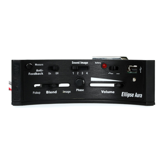
- Page 3 4. Fasten the pickup wires to the terminal block on the preamp module (fi gure 2). The signal wire goes to the terminal marked “IN,” and the shield wire goes to the “GND” terminal. Tighten the screws on the terminal block to secure the wires. Figure 3.
- Page 4 9. Upload Images Install the included Aura Image Gallery software on your computer. Connect the included “mini-B” USB cable between the Ellipse Aura preamp and the computer (fi gure 5). Follow the onscreen instructions to upload Images. Warning: If you upload Images before installing the preamp, observe ESD handling and other precautions outlined in the beginning of these instructions.
Need help?
Do you have a question about the ELLIPSE AURA and is the answer not in the manual?
Questions and answers