Advertisement
Available languages
Available languages
Quick Links
Download this manual
See also:
User Manual
Advertisement

Subscribe to Our Youtube Channel
Related Manuals for WANDERS BORDEAUX


Summary of Contents for WANDERS BORDEAUX
- Page 1 INSTALLATIE EN BEDIENINGSVOORSCHRIFTEN VOOR: INSTALLATION AND OPERATION INSTRUCTIONS FOR: BORDEAUX www.wanders.com NL GB...
- Page 2 INHOUDSOPGAVE 1.0 TECHNISCHE AANWIJZINGEN VOOR INSTALLATEUR 2.0 INSTALLATIE VOORSCHRIFTEN TECHNISCHE AANWIJZINGEN 2.1.1 SCHOORSTEEN INSTALLEREN VAN DE KACHEL AANSLUITEN VAN DE SCHOORSTEEN AANSLUITING VAN DE GASLEIDING ONDERHOUD HOUTSET AFSTANDSBEDIENING GEBRUIKS AANWIJZING AFSTANDSBEDIENING 3.0 GEBRUIKERS HANDLEIDING INGEBRUIK STELLEN VAN DE KACHEL BUITEN WERKING STELLEN VAN DE HOOFDBRANDER BUITEN WERKING STELLEN VAN DE WAAKVLAM VOORSCHRIFTEN VOOR DE GEBRUIKER TTB BEVEILIGING...
- Page 3 1.TECHNISCHE AANWIJZINGEN VOOR INSTALLATEUR Belangrijk Voordat u de gashaard plaatst en in gebruik neemt, is het zaak deze instructies zorgvuldig te lezen. Bewaar ze!!! Bij de constructie van onze kachels hebben wij niet alleen de grootste aandacht besteed aan uitvoering en uiterlijk, maar ook aan een maximale gebruiksvriendelijkheid en bedrijfszekerheid.
- Page 4 2.2 Installeren van de kachel Verwijder de verpakking. 1 Verwijder de twee schroeven achter de bedieningsdeur (zie fig. 1) en het glasraam eraf beuren. 2 Verwijder de vier schroeven van de sierlijst en de sierlijst wegnemen (zie fig. 2) Fig.1 Fig.2 3 Verwijder de twee schroeven van het schoorsteen aansluitstuk en schuif de plaat uit de rails (zie fig.
- Page 5 2.3 Aansluiten van de schoorsteen. De gashaard is standaard voorzien van een open trekonderbreker met valwindafleider. Gebruik voor de verbinding vanaf het toestel tot schoorsteenkanaal corrosievast materiaal. De binnendiameter van de pijp moet minimaal 100mm zijn. De aansluiting van het toestel op het schoorsteenkanaal dient deugdelijk en lekkagevrij te zijn. 2.4 Aansluiting van de gasleiding.
- Page 6 Fig. 4a Fig. 4b Fig. 4c...
- Page 7 2.8 Afstandsbediening. Plaats de ontvanger van de afstandsbediening links onderin het toestel voordat u de sierlijst plaatst ( fig. 6 ). Schuif de kabel tussen de buitenmantel en de bodem plaat van de verbrandingskamer. Fig. 6 Aansluiting microschakelaar Aansluiting motor ONTVANGER KABEL STEKKERS...
- Page 8 2.9 Gebruiks aanwijzing afstands bediening. Instellen van de display (van F/12h naar C/24h en omgekeerd) Na het plaatsen van de batterij (9v alkaline) of door het te gelijktijdig indrukken van de knoppen AUTO en TIMER begint de aanduiding te knipperen tijdens het knipperen van de display kan men omschakelen van F naar C door het indrukken van de AUTO knop kan men omschakelen.
- Page 9 Timer (TIMER) Als de timer modus is ingeschakeld is de temperatuur regeling hetzelfde als in de AUTO modus tijdens de uitschakel tijden schakelt de motor hel toestel op waakvlam. Ter controle van de ingestelde temperatuur AUTO indrukken en aansluitend in de TIMER modus terugkeren. Tijdens de uitschakel tijd vind er geen temperatuur controle plaats, het batterij verbruik van de zender is daardoor zeer gering.
- Page 10 3.0 GEBRUIKERS HANDLEIDING In het midden van het toestel achter de klep bevinden zich de bedieningsknoppen van de kachel. KNOP B KNOP A 3.1 In gebruik stellen van de kachel. Open de gaskraan welke in de gastoevoerleiding naar de gaskachel is gemonteerd. Draai de ontstekingsknop - A - rechtsom in de richting van ontsteken tot aan de aanslag, vervolgens indrukken en enkele seconden wachten.
- Page 11 De brander kan ook uitgeschakeld worden door de ontstekingsknop - A - rechtsom te draaien tot aan de aanslag. KNOP D KNOP E 3.3 Buitenwerking stellen van de waakvlam. Door de ontstekingsknop - A - licht in te drukken en verder rechtsom te draaien schakelt u de waakvlam uit.
- Page 12 3.5 TTB beveiliging De kachel is voorzien van een thermische terugslag beveiliging ( TTB ) dit is een temperatuur schakelaar die in werking treedt als het afvoerkanaal onvoldoende trek heeft zodat de rookgassen in het vertrek komen, als dit het geval is zal het toestel uitslaan.
- Page 13 G25 I2L 0,501 G20/G25 I2E+ 20/25 0,445 G20/G25 I2E+ 0,445 G20 I2H 0,445 G20 I2ELL 0,445 G20 I2H 0,445 G20 I2H 0,445 G20 I2H 0,445 G20 I2H 0,445 G20 I2H 0,445 G20 I2E 0,445 G20 I2H 0,445 A: LAND E: BRANDERDRUK B: GASSOORT F: SPUITSTUK CODE C: VOORDRUK...
- Page 14 GARANTIE BEPALINGEN Wanders Metaalproducten b.v. te Netterden garandeert gedurende 1 jaar na aankoopdatum de goede werking van de gashaard, mits het toestel vakkundig is geïnstalleerd en gebruikt volgens de gestelde aanwijzingen. De garantie omvat alle gebreken die te herleiden zijn tot constructie- en mate- riaal fouten en omvat het gratis leveren van nieuwe onderdelen.
- Page 15 SCHUIFPLAAT BUITENMANTEL BRANDERSET VERBRANDINGSKAMER SIERLIJST GLASRAAM...
- Page 17 INSTALLATION AND OPERATION INSTRUCTIONS FOR BORDEAUX GAS INSET STOVE...
- Page 18 We are therefore fully confident that you will enjoy this appliance for years and years to come. INDEX DATA SHEET for the Bordeaux gas inset stove. 4.0 TECHNICAL INSTRUCTIONS FOR FITTER INSTRUCTIONS FOR INSTALLATION TECHNICAL INSTRUCTIONS...
-
Page 19: Natural Gas (N.g.)
NATURAL GAS (N.G.) NATURAL GAS (N.G.) G20 I2H A: COUNTRY G.B. B: TYPE OF GAS G20 I2H C: INPUT 4.3kw D: OUTPUT (MAX) 3.5kw E: OUTPUT (MIN) 2.7kw F: EFFICIENCY 81% (nett) G: PRESSURE. (STANDING) 20mbar H: PRESSURE (OPERATING) 16mbar I: CONSUMPTION (MAX) 0.445m3/hr J: NOZZLE CODE No. -
Page 20: Instructions For Installation
1. TECHNICAL INSTRUCTIONS FOR FITTER IMPORTANT It is important to read these instructions before you install the fire. After commissioning the installation, go through the operation of the unit with the customer and leave these instructions with them. Make sure that they store these instructions in a safe place. SECTION 5.0 THIS SECTION TO BE COMPLETED AND SIGNED BY THE INSTALLATION ENGINEER. - Page 21 2.2 Chimney requirements When an appliance has previously been connected to the chimney, the chimney must be cleaned by a professional. Although a gas fireplace can operate well on a little chimney draw, we advise you to have the chimney checked for soundness and correct operation annually. An approved gas cowl may be fitted to improve the operation of the chimney.
- Page 22 Remove the two screws of the flue adaptor and slide it out of the rails. (FIG. 3) If the chimney is to be lined with a flexible liner, secure this to the flue adaptor using proprietary heat proof sealant. Additional securing may be necessary. Now place the fireplace in the recess and slide the flue adaptor piece back into place, screw the two self tapping screws in place to retain it.
- Page 23 2.7 TTB This apparatus is equipped with TTB safety mechanism, this shuts off the gas supply to the burner when the chimney is blocked. If this is the case, the apparatus will shut down. When this happens, it is usually an indication of a problem with the chimney. If this is found to be o.k. then check the pilot/gas supply.
- Page 24 2.9 FITTING THE LOG SET • THE CERAMICS VARY DEPENDING ON WHETHER THE FIRE IS SET TO RUN ON NATURAL GAS OR L.P.G. • REFER TO THE PICTURES ON THE NEXT PAGES TO ASSIST CORRECT POSITIONING OF THE CERAMICS. • Take great care when handling the ceramic logs as they are very fragile.
- Page 25 LOG LAYOUT FOR NATURAL GAS FIG. 4A FIG 4A FIG. 4b FIG 4B FIG 4C...
-
Page 26: Remote Control
3.0 USER INSTRUCTIONS 3.1 POSITIONING THE REMOTE CONTROL RECEIVER. Place the remote control receiver in the bottom left corner of the unit before you mount the decorative frame (check FIG. 6). Slide the cable between the outer casing and the bottom of the combustion chamber. -
Page 27: Auto Timer
3.3 REMOTE CONTROL OPERATING INSTRUCTIONS HIGHER The two large buttons on the remote control hand-set are used to operate the main burner. AUTO The two smaller buttons are for AUTO and TIMER. TIMER Instructions for their use follow. LOWER SETTING THE DISPLAY After fitting the batteries in the receiver and the hand set, the following options are available: Adjustment of the digital display (from ‘DEGREES F &... -
Page 28: Manual Mode
MANUAL MODE ADJUSTING THE HEIGHT OF THE FLAMES MANUALLY, ONCE THE PILOT HAS BEEN LIT. • HIGHER LOWER Press ) to start the fire or to make the flames higher. Press ) to make the PILOT ON flames smaller or to switch the fire to the position. - Page 29 3.4 OPERATING THE FIRE FOR THE FIRST TIME In the middle of the apparatus, below the main glass there is a drop down door that hides the main controls. (shown below) KNOB KNOB ‘A’ ‘B’ Open the gas tap which is mounted in the gas pipe leading to the fireplace. Turn the ignition button (A) clockwise, all the way to the end stop.
- Page 30 3.6 USER GUIDELINES. • Do not use the fire until an authorised fitter has commissioned the unit and carried out the required safety tests. • The TTB fitted to this appliance is not a substitute for an independently fitted carbon monoxide detector.
- Page 31 EXPLODED VIEW OF STOVE COMPONENTS FLUE ADAPTOR OUTER CASING COMBUSTION CHAMBER BURNER ASSEMBLY DECORATIVE FRAME GLASS WINDOW...
-
Page 32: Technical Drawing
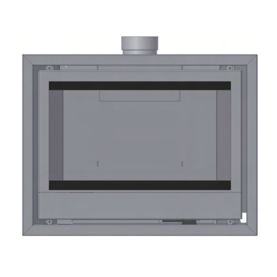
TECHNICAL DRAWING... -
Page 33: Annual Service Record
ANNUAL SERVICE RECORD INSTALLATION DATE OF APPLIANCE: 1ST YEAR SERVICE completion date: SERVICE ENGINEER: COMPANY NAME: COMPANY ADDRESS: POSTCODE: CONTACT NUMBER 2ND YEAR SERVICE completion date: SERVICE ENGINEER: COMPANY NAME: COMPANY ADDRESS: POSTCODE: 3RD YEAR SERVICE completion date: SERVICE ENGINEER: COMPANY NAME: COMPANY ADDRESS: POSTCODE:... - Page 34 STOVE INSTALLATION SPECIFICATION & INFORMATION THIS SECTION TO BE COMPLETED AND SIGNED BY THE INSTALLATION ENGINEER Type gas supply (please tick) Natural (mains) Gas _______LPG supply in bulk_______ LPG supply in cylinder________ Size of Governor setting: (i.e.) Natural Gas 20MBAR. LPG 37MBAR) Length and size of gas supply:__________ Meter pressure.
- Page 35 Guarantee Dear Customer, Your gas fire, when installed in accordance with the installation instructions and operated in accordance with these instructions, should provide many years of safe and efficient operation. We thank you for purchasing our product and trust it will provide excellent service. This appliance carries a guarantee of 2 Years from date of purchase.
- Page 36 Ink.00.7066 Wanders METAALPRODUCTEN B.V. AMTWEG 4 7077 AL Netterden (NL) Tel. +31 (0)315-386414 Fax +31 (0)315-386201 e-mail: info@wanders.nl www.wanders.com...
Need help?
Do you have a question about the BORDEAUX and is the answer not in the manual?
Questions and answers