Advertisement
Quick Links
Technical Service Guide
July 2018
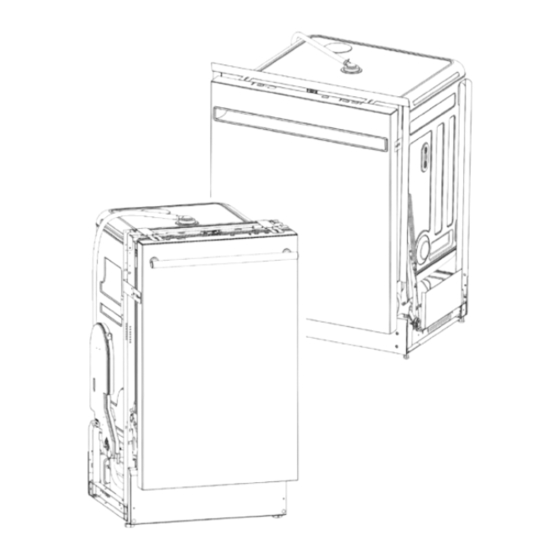
18" and 24" Stainless Steel Tub
ADA Compliant Dishwasher
GDT225SGL0BB
GDT225SGL0WW
GDT225SSL0SS
GDT226SGL1BB
GDT226SGL1WW
GDT226SSL0SS
GDT226SSL1SS
PDT145SGL0BB
PDT145SGL0WW
PDT145SSL0SS
QDT125SGL0BB
QDT125SGL0WW
QDT125SSL0SS
ZDT165SIL0II
ZDT165SSL0SS
31-9291
Rev. 2 ~ 10/14/2020
Advertisement

Related Manuals for Haier GE QDT125SSL0SS


Summarization of Contents
Safety Information
IMPORTANT SAFETY NOTICE
Notice regarding use of service guide by qualified individuals, manufacturer liability.
WARNING: Power and Grounding
Warning to disconnect power before servicing and reconnect grounding devices.
Safety Requirements
WARNING: Lockout / Tagout (LOTO)
Warning about the Lockout / Tagout (LOTO) 6 Step Process.
Nomenclature
Model Number Breakdown
Breakdown of model number components and their meaning.
Serial Number Identification
Explanation of how serial number identifies month and year of manufacture.
Specifications
Electrical Specifications
Table detailing voltage, resistance, watts, amps, and GPM for components.
Installation
Side Mounting for 18" Models
Instructions for side mounting 18-inch dishwasher models.
Top Mounting for 18" Models
Instructions for top mounting 18-inch dishwasher models.
Top Mounting for 24" Models
Instructions for top mounting 24-inch dishwasher models.
Side Mounting for 24" Models
Instructions for side mounting 24-inch dishwasher models.
Operation
Auto Hot Start Feature
Explanation of the Auto Hot Start feature and its impact on cycle time.
Close Loop Dry System
Description of the European-style closed-loop dry system and rinse aid use.
Component Locator Views
Bottom View
Diagram labeling components visible from the bottom of the dishwasher.
Left Side / Rear View
Diagram labeling components visible from the left side/rear of the dishwasher.
Control Board and Connector Locator View
Control Board Covers and RJ45 Location
Diagram showing mounting cover, front cover, and RJ45 connector location.
Control Board Component Layout
Diagram of the main control board with labeled fuses and connectors.
Door and Balance Systems
GE - 24 Inch Models System
Description of the door balance system for GE 24-inch models.
18 Inch Haier, Profile, Monogram SS Models
Door balance system for 18-inch Haier, Profile, and Monogram SS models.
Monogram II Models System
Door balance system for Monogram II models with custom panels.
Door Design: GE, Haier, Profile, Monogram SS
Details on the door design for GE, Haier, Profile, and Monogram SS models.
Top Console Cover and Removal
Information on the console cover securing and removal.
Outer Door Panel Removal
Instructions for removing the outer door panel.
UI (User Interface) and Console Details
Description of UI controls and console assembly.
Monogram II Custom Door Panel Removal
Details specific to the Monogram II custom door panel and its removal.
Console and UI Removal Steps
Step-by-step guide for removing the console and UI.
Inner Door Information
Information on inner door attachment to hinges.
Inner Door Removal from Hinges
Procedure to remove the inner door from the hinges.
Hinges and Braces
Crossbar or Stiffener Bar
Description of the stiffener bar in GE 24-inch and 18-inch models.
Removing Hinges on 24-Inch GE Models
Step-by-step guide for removing hinges on 24-inch GE models.
Hinges Linkage
Removing Hinges from 18 Inch Models
Procedure for removing hinges from 18-inch models.
Door Gasket and Splash Guard
24-Inch GE Model Door Gasket
Details on the door gasket for 24-inch GE models.
18-Inch Haier, GE, Monogram Models Gasket
Description of the door gasket for 18-inch Haier, GE, and Monogram models.
Replacing Door Gasket on 18-Inch Models
Instructions for replacing the door gasket on 18-inch models.
Detergent and Rinse Aid Module
Detergent Dispenser Removal
Steps to remove the detergent dispenser.
Detergent Module Diagnosis
Diagnostic procedures for the detergent module, including resistance checks.
Tub and Structure
Toe Kick Panel(s) Description and Removal
Description and removal of the toe kick panel.
Junction Box and House Wiring Connection
Location and connection details of the junction box.
Leveling Legs Adjustment
Information on the function and adjustment of leveling legs.
Latch System
Latch and Switch Assembly
Diagrams of the latch and switch assembly.
Latch System Diagnosis
Diagnostic information for the latch system switches.
Racks
Lower Rack Roller Description
Description and removal of lower rack rollers.
Upper Rack Height Adjustment
Information on adjusting the height of the upper rack.
Electronic Controls
Error Code Display Mode
Procedure to enter and exit error code display mode.
Door Status Check
How the control reports door status.
Demo Mode Entry and Exit
Procedure to enter and exit demo mode.
Service Mode and UI Details
Service Mode Operation
Procedure for entering and exiting service mode and test descriptions.
Main Control (MC) Service LED
Function of the service LED on the main control.
User Interface (UI) Assembly
Description of the UI assembly and troubleshooting.
Fill System
Fill System Components Overview
Diagrams showing various fill system components like air gap, flow meter, and fill valve.
Flow Meter Description
Explanation of how the water flow meter works.
Fill Hoses and Sump Port
Description of fill hoses and the sump fill port.
Fill Valve and Flood Switch Function
Details on fill valve and flood switch operation.
Flood Switch Components and Diagnosis
Diagram of flood switch parts and diagnostic procedures.
Sump
Sump Top and Bottom Views
Diagrams showing the top and bottom views of the sump assembly.
Sump Ports Identification
Diagram showing various ports on the sump.
Circulation Pump Inlet Cover
Description and removal of the circulation pump inlet cover.
Drain Pump Inlet from Sump
Description of the drain pump inlet from the sump.
Circulation System
Upper Sprayer and Conduit Description
Description of upper sprayer, main conduit, and mid spray arm.
Lower Spray Arm and Support
Description and removal of lower spray arm and its support.
Turbidity Sensor and Thermistor
Thermistor Specifications
Table of thermistor voltage, resistance, and temperature readings.
Turbidity Sensor Calibration and Diagnostics
Explanation of calibration, diagnostics, and removal of turbidity sensor.
Circulation Pump and Motor
Diagnosing the Circulation Pump
Procedure to diagnose the circulation pump motor resistance.
Drain System
Drain Pump Removal and Diagnosis
Procedure for removing and diagnosing the drain pump.
Dry System (Hidden Heater)
Diagnosing the Heater
Procedure to diagnose the hidden heater resistance.
Need help?
Do you have a question about the GE QDT125SSL0SS and is the answer not in the manual?
Questions and answers