Advertisement
Quick Links
Advertisement

Related Manuals for Unimig STEALTH 2400


Summary of Contents for Unimig STEALTH 2400
- Page 1 VERSION 1.2.1228.0 U11097 + U11098 | Operating Manual...
- Page 2 5.19 Setting the Voltage Divider 6.14.6 Cut Direction & Angle 5.20 Assembling the CNC Plasma Torch 6.15 Active Cut Mode & Standby Mode 5.21 Connecting the CNC Torch 6.16 Operating the Air Compressor 5.22 Mounting the CNC Torch to the Table STEALTH 1200 & 2400 Operating Manual...
- Page 3 7.1 Maintaining the CNC Table 7.2 Maintaining the Consumables 8. Troubleshooting 8.1 Plasma Cutter Troubleshooting 8.2 Plasma Troubleshooting 8.4 CNC Troubleshooting 8.5 Alarms 9. Plasma Cutting Guide 11. Pinout Guide 11.1 VIPER CUT 30 Mk II 11.2 RAZOR CUT 45 11.3 RAZOR CUT 80 11.4 RAZOR CUT 120/160 12. Recommended Accessories STEALTH 1200 & 2400 Operating Manual...
- Page 4 Damage caused in this manner will not be covered under warranty. • Only qualified persons should install, operate, maintain, and repair this equipment. • During operation, keep everyone, especially children, away. STEALTH 1200 & 2400 Operating Manual...
- Page 5 Magnetic fields can affect Implanted Medical Devices. • Wearers of Pacemakers and other Implanted Medical Devices should keep away. • Implanted Medical Device wearers should consult their doctor and the device manufacturer before going near any plasma cutting. STEALTH 1200 & 2400 Operating Manual...
- Page 6 • Wear proper PPE and body protection made from durable, flame-resistant materials like leather. • Read and understand the Safety Data Sheets (SDSs) and the manufacturerʼs instructions for adhesives, coatings, cleaners, consumables, coolants, degreasers, fluxes, and metals. STEALTH 1200 & 2400 Operating Manual...
- Page 7 PLEASE NOTE that under no circumstances should any equipment or parts be altered or changed in any way from the standard specification without written permission given by UNIMIG. To do so will void the warranty. STEALTH 1200 & 2400 Operating Manual...
- Page 8 It is the userʼs responsibility to follow all instructions and safety precautions to ensure proper use table. Non-compliance with these guidelines may void any warranties and relieve Welding Guns of Australia Pty Ltd. of any liability. STEALTH 1200 & 2400 Operating Manual STEALTH 1200 & 2400 Operating Manual...
- Page 9 Package Contents 2. Package Contents Table Body Table Legs x 4 (STEALTH 1200) Ball Valve x 2 Table Legs x 6 (STEALTH 2400) Table Slats Computer Arm Control PC Electrical Cabinet EMERGENCY STOP Emergency Stop (E-Stop) Accessories Box which includes: Manual Plate &...
- Page 10 Software + CAM/Nesting Software + CAM/Nesting Software Included Software Included Control PC Specifications Parameter Values Operating System Windows 10 Screen Panel 21” Touchscreen Hardware Intel Core i3, 8GB RAM, 128GB Networking Ethernet, Wi-Fi, Bluetooth STEALTH 1200 & 2400 Operating Manual...
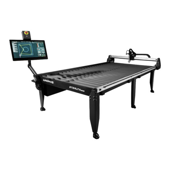
- Page 11 1.2x2.4m full-sheet cut size. The gantry will travel tables allow you to produce more parts and projects 1.23x1.22m on the STEALTH 1200 CNC, and 1.23x2.44m efficiently. Optimise your cuts and nest parts on full sheets on the STEALTH 2400 CNC, so you can guarantee youʼll to minimise loading time and reduce material waste.
- Page 12 Top View Layout 1. THC 8. Electrical Box 2. Laser 9. Control PC 3. CNC Torch 10. Computer Arm 4. Water Bed 11. Gantry 5. Rail 12. Emergency Stop Button 6. Table Legs 7. Table Feet STEALTH 1200 & 2400 Operating Manual...
- Page 13 Machine Overview Right Side View Layout 13. Water Bed Valves Left Side View Layout 14. Earthing Plate 15. THC Divider STEALTH 1200 & 2400 Operating Manual...
- Page 14 7. Laser Point & Proximity Switches 4.4 Arc Voltage Box Layout 1. ARC (Arc Ignition) 2. ARC (Arc Ignition) 3. OK (CNC Feedback) 4. OK (CNC Feedback) 5. VOL - (Arc Voltage) 6. VOL + (Arc Voltage) STEALTH 1200 & 2400 Operating Manual...
- Page 15 CNC table to cease operation immediately. 4.6 THC Divider Layout 1. Cable 5 2. Arc Voltage Box Connection 3. Ohmic Sensor (Not Used for UNIMIG STEALTH CNC Tables) 4.7 Control PC Layout 1. Power On/Off Button 2. Power Plug 3. USB Ports 4.
- Page 16 Installation 5. Installation 5.1 Tools Required Forklift or Lifting Crane (Recommended) Thread Seal/PTFE Tape Leveller Square Tool Allen Keys Flat & Phillips Head Screwdrivers STEALTH 1200 & 2400 Operating Manual...
- Page 17 Installation 5.2 Installing the Table Slats 1. Slot the table slats into the pre-cut holes across the CNC table. STEALTH 1200 & 2400 Operating Manual...
- Page 18 3. Undo the screws on the table and use these to screw the legs in. The shorter screws go in the top holes, and the longer screws go in the bottom holes. STEALTH 1200 & 2400 Operating Manual...
- Page 19 While the table is in the air and it is easy to reach, install the valves for the water bed. 1. Use thread seal/PTFE tape to wrap the drainage pipe to create a leakproof seal. 2. Screw on the ball valve. STEALTH 1200 & 2400 Operating Manual...
- Page 20 Installation 3. Check that the valve is working correctly by opening and closing the valve lever. 4. Do this on both drainage pipes. STEALTH 1200 & 2400 Operating Manual...
- Page 21 5.5.1 Levelling the Table 1. Place a levelling tool on the table to determine its level. 2. Raise or lower the wheels as needed using the levelling nut at the top of the wheels. STEALTH 1200 & 2400 Operating Manual...
- Page 22 1. Twist the red wheel lock nut counterclockwise to lower the stopper and lock the wheel. 5.5.3 Unlocking the Wheels 1. Twist the red wheel lock nut clockwise to raise the stopper and unlock the wheel. STEALTH 1200 & 2400 Operating Manual...
- Page 23 1, 2, 3, 4 & 7, plug cables 1 to 4 in from left to right, top to bottom, with 1 in the top left and 4 in the bottom left plugs. Cable 7 connects to the bottom middle plug. STEALTH 1200 & 2400 Operating Manual...
- Page 24 1. Mount the Torch Height Controller (THC) to the gantry motor box using the M6 hex screws. 2. Plug in the 4-pin connection plug from the gantry rail into the top of the THC. STEALTH 1200 & 2400 Operating Manual...
- Page 25 5.8.1 Installing the Computer Arm 1. Undo the screws on the front leg (A) of the short side of the table and attach the computer arm mounting bracket on the side of the table. STEALTH 1200 & 2400 Operating Manual...
- Page 26 2. Place the base plate of the arm on the bracket and screw it in using the long hex screw inside the centre piece. 3. Take the lower arm segment (with the open ends) and place it onto the base plate so that the cable openings face downwards. STEALTH 1200 & 2400 Operating Manual...
- Page 27 Installation 4. Take the upper arm segment and place it onto the lower arm. 5. Tighten the two screws in the lower arm to ensure the arm is properly installed and tight. STEALTH 1200 & 2400 Operating Manual...
- Page 28 3. Screw the X mounting bracket and E-Stop plate into the back of the Control PC using the M4 hex screws. 4. Remove the small nut from the top of the upper arm mounting point. STEALTH 1200 & 2400 Operating Manual...
- Page 29 5. Lift the Control PC and slide it onto the mounting point on the upper arm, so the L brackets slide over the edges and the holes line up. 6. Screw the small nut back in to hold it in place. STEALTH 1200 & 2400 Operating Manual...
- Page 30 Plugging the ethernet cable into the LAN2 port will not work, the computer will not recognise it. 10. Screw the grounding cable into the grounding connection on the bottom right side of the screen (facing the back of the PC). STEALTH 1200 & 2400 Operating Manual...
- Page 31 12. Hold the bundle of computer cables against the upper arm and replace the cap over the cables by lining up the bottom slots and locking it into place. Replace the screw in the upper part of the cap. STEALTH 1200 & 2400 Operating Manual...
- Page 32 13. Remove the lower arm cable management cap by sliding it upwards and off. 14. Hold the bundle of computer cables against the lower arm and replace the cap by sliding it back into place. STEALTH 1200 & 2400 Operating Manual...
- Page 33 1. Plug the 4-pin cable into the 4-pin connection on the front of the electrical cabinet. 2. Plug the 3-pin earth cable into the 3-pin connection on the front of the electrical cabinet. 3. Plug the ethernet cable into the ethernet port. STEALTH 1200 & 2400 Operating Manual...
- Page 34 Installation 5.10 Connecting the Power Cable to the Electrical Cabinet 1. Plug the power cable into the front of the electrical cabinet. STEALTH 1200 & 2400 Operating Manual...
- Page 35 The THC Divider should be installed so that the green connection port is pointing towards the electrical cabinet. CABLE 5 There are three cables on the THC divider. Divider Plasma CNC Port Arc Voltage STEALTH 1200 & 2400 Operating Manual...
- Page 36 6 exits the Arc Voltage box. Plug the cable labelled 6 into the back of the electrical cabinet. The third cable is used for ohmic IHS functions. UNIMIG plasma cutters do not have ohmic IHS capabilities, so this cable remains unplugged.
- Page 37 Arc success signal For all UNIMIG plasma cutter pinout connections see “11. Pinout Guide” on page 117. For all non-UNIMIG plasma cutters, contact the manufacturer for pinout diagrams and instructions on the correct pinouts. STEALTH 1200 & 2400 Operating Manual...
- Page 38 2. Screw the earthing plate into the leg through the leg holes via the left and centre holes, using the screws that were just removed. The earthing plate should overhang on the right side. 3. Screw an M8 screw into the remaining hole on the earthing plate. STEALTH 1200 & 2400 Operating Manual...
- Page 39 The earth clamp that connects the plasma cutter to the CNC table is the positive (+) terminal of the plasma cutter. To the Plasma Cutter 1. Connect the earth clamp to the dinse connection on the plasma cutter. STEALTH 1200 & 2400 Operating Manual...
- Page 40 The grounding rod works to eliminate any electrical interference produced by the plasma cutter and plasma cutter. protects the CNC table from potential damage caused by this interference. A qualified electrician should be contacted to ensure proper installation of the grounding rod and earth leads. STEALTH 1200 & 2400 Operating Manual...
- Page 41 2. While the table is filling with water, add the Plasma Table Treatment as directed. See “3. Technical Specifications” on page 10 for the litre capacity of the table. CNC Plasma Table Treatment Water Source STEALTH 1200 & 2400 Operating Manual...
- Page 42 Installation Emptying the Water Bed 1. Open the valves on the bottom of the table to allow the table to drain. For faster drainage, a water pump can be used. STEALTH 1200 & 2400 Operating Manual...
- Page 43 2. Set the air pressure on the compressor. It is recommended to set the air pressure slightly higher than the plasma cutterʼs, to allow for any drops in pressure depending on the hose length. Air Compressor STEALTH 1200 & 2400 Operating Manual...
- Page 44 1. Connect the filter to the air compressor. 2. Connect the filter to the plasma cutter via a second air hose. Air Compressor STEALTH 1200 & 2400 Operating Manual...
- Page 45 1. Screw the electrode into the torch head. Fasten securely. 2. Place the swirl ring onto the electrode. 3. Screw the cutting tip into the torch head. Fasten securely. 4. Screw the retaining cap into the torch head. Fasten securely. STEALTH 1200 & 2400 Operating Manual...
- Page 46 Installation 5.21 Connecting the CNC Torch 1. Assemble the CNC torch. 2. Connect the CNC torch into the Euro central connection. STEALTH 1200 & 2400 Operating Manual...
- Page 47 Installation 5.22 Mounting the CNC Torch to the Table 1. Remove the clips from the drive rail. 2. Feed the torch through the rail and replace the clips to hold it in place. STEALTH 1200 & 2400 Operating Manual...
- Page 48 6. If the torch needs to be adjusted, the back screw on the torch mount can be loosened and the angle adjusted. 90° Check that the CNC tableʼs rails and drive system are clean and the torch travels smoothly. Unsteady machine motion can cause a regular, wavy pattern on the cut surface. STEALTH 1200 & 2400 Operating Manual...
- Page 49 Connect the table and machine plugs into the mains socket, then switch the Plasma Cutter, the Control PC and the CNC table ON. Plasma Cutter Electrical Cabinet Control PC STEALTH 1200 & 2400 Operating Manual...
- Page 50 ArcPath is the CNC control program that UNIMIG has designed in-house to be a quick and easy-to-use control interface. It can be used via the touchscreen for quick and intuitive CNC control, or it can be used with a mouse and keyboard.
- Page 51 (from the origin) or relative positioning (from the current position). Specifies relative movement or positioning along the X-axis when using X-axis relative coordinates. incremental mode (where movement is described relative to the previous point rather than an absolute position). STEALTH 1200 & 2400 Operating Manual...
- Page 52 G04 Pn Commands the machine to pause for a specified Time delay (where Pn=time in seconds) amount of time. (P100 = 1 second) Imperial unit Sets the table to use imperial units (inches). measurement STEALTH 1200 & 2400 Operating Manual...
- Page 53 Once the G92 command is issued, all movements and operations will be referenced from this point. The coordinates can be reset manually by Reference point specifying new ones. settings If no parameters are provided, the default is (0,0 or X0,Y0). STEALTH 1200 & 2400 Operating Manual...
- Page 54 Initiates the perforation cycle and turns on the arc. End of perforation Ends the perforation cycle and turns off the arc. cycle Turn on the spray Starts the spray of powder, used for surface coating applications. powder STEALTH 1200 & 2400 Operating Manual...
- Page 55 Remove spray offset needed. Program end with Marks the end of the program and stops the machine. It also resets the machine settings to their initial reset state and rewinds the program to the beginning. STEALTH 1200 & 2400 Operating Manual...
- Page 56 Set the cut speed and cutting parameters. Jog Panel Manually control the movement of the torch head. Cut Status Panel Control the status and progress of the cut. The alarm status is also displayed here. STEALTH 1200 & 2400 Operating Manual...
- Page 57 Operation 6.4 Power Options Menu Function Description Restart Program Restart the ArcPath program. Close Program Close the ArcPath program. Restart Table Restart the STEALTH CNC table. Turn Off PC Turn off the Control PC. STEALTH 1200 & 2400 Operating Manual...
- Page 58 The system will override the standard kerf width based on job-specific settings. Sets the allowable tolerance when cutting corners. A lower value provides more precision, but a Corner Tolerance 0.001 - 1 higher value allows for faster cutting through sharp angles or corners. STEALTH 1200 & 2400 Operating Manual...
- Page 59 Continuous Spray On / Off Allows a continuous spray for marking processes that use spraying. Not Torch Up Spraying Output On / Off Allows the spray output for marking processes that use spraying. Enable STEALTH 1200 & 2400 Operating Manual...
- Page 60 THC1 / THC2 / THC3 Init THC Connect Force a connection the the THC that has been set to On if the THC fails to connect automatically. / THC4 Restore Defaults Restores all settings to their default value. STEALTH 1200 & 2400 Operating Manual...
- Page 61 The Information section of the System Settings menu displays the Model Number and Serial Number of the STEALTH CNC table, as well as the Version of software itʼs running. It also displays the Support Contact details. STEALTH 1200 & 2400 Operating Manual...
- Page 62 Tool Parameters Backup can be saved on a USB as well as the Control PC. Tool Parameters Restore a saved Tool Parameters Backup file by navigating to the file location and recovering it. Recovery STEALTH 1200 & 2400 Operating Manual...
- Page 63 Choose From Popup Displays a popup menu to select where the torch will return to. Use Home Switch / Home Switch Type Sets which type of switch defines the home position. Use Limit Switch STEALTH 1200 & 2400 Operating Manual...
- Page 64 The upper Soft Limit of the axis, the axis cannot move beyond this limit in the positive direction. -99999.9 - 99999.9mm This setting is only active when Soft Limit is enabled. STEALTH 1200 & 2400 Operating Manual...
- Page 65 Enables the use of two motors for synchronised, precise control of the transverse axis. The settings available on the Axis Settings panel will depend on the whether the Rail (X), Transverse (Y) or Height (Z) axis is selected. STEALTH 1200 & 2400 Operating Manual...
- Page 66 • Set Arc Voltage • Set Arc Current • Kerf Hole • Cut Height • Cut Speed Hole • Advance Off The settings available in the Cut Parameters will depend on the selected equipment vendor. STEALTH 1200 & 2400 Operating Manual...
- Page 67 Plasma Power Vendor (F9) Select the vendor from the dropdown menu. Import Database (F10) Import the cutting databases available to the selected vendor. Export Database (F11) Export the cutting databases available to the selected vendor. STEALTH 1200 & 2400 Operating Manual...
- Page 68 Enables the use of a cylinder-based THC system which uses pneumatic mechanisms to control Cylinder THC Enable On / Off the torch height. Watch Arc Enable On / Off Allows the system to actively monitor the plasma arc, checking for issues like arc loss or instability. STEALTH 1200 & 2400 Operating Manual...
- Page 69 When enabled, the table will ignore any torch crashes or issues that occur when the table is On / Off When Pause paused. Consumables Displays the list of consumable parts for the selected torch. STEALTH 1200 & 2400 Operating Manual...
- Page 70 0 indicates that collisions are not allowed. Locate Low Speed 0 - 50 Sets the speed at which the torch moves when it is in the locating phase (such as during homing). (P33) STEALTH 1200 & 2400 Operating Manual...
- Page 71 Arc On Pin Selection Specifies which pin on the control board is responsible for sending the arc on signal. (P31) THC Mode (P32) Arc Mode Sets the operational mode of the Torch Height Control (THC) system. STEALTH 1200 & 2400 Operating Manual...
- Page 72 Displays the status of the upper limit switch for the torch movement. When green, the upper limit has been reached. Motor Down Limit Displays the status of the lower limit switch for the torch movement. When green, the lower limit has been reached. STEALTH 1200 & 2400 Operating Manual...
- Page 73 Displays whether a collision has been detected between the torch and the material or an obstruction. When green, a collision has been detected. Perforation Completion Displays whether the perforation (piercing) process has been completed. When green, the piercing process has finished. STEALTH 1200 & 2400 Operating Manual...
- Page 74 Proximity Switch NC / NO When set to NC, the proximity switch circuit is closed until the torch gets too close to the material, and then it opens, triggering a response to avoid a collision. STEALTH 1200 & 2400 Operating Manual...
- Page 75 The Output definition of the 1627 THC models is fixed, so there are no available outputs. It is not recommended to adjust these outputs, these are used to complete the activation and setup of the THC on the CNC table. STEALTH 1200 & 2400 Operating Manual...
- Page 76 It is not recommended to adjust these outputs, these are used to complete the activation and setup of the THC on the CNC table. If there is no connection or the connection is lost, an error message will pop up “Lost connection, canʼt import/export!” STEALTH 1200 & 2400 Operating Manual...
- Page 77 8421 Bit7 Cut Mode z_limit_p plasma_switch_gas z_limit_n motion auto_start spray_torch_up auto_stop spray_torch_down ArcPath needs to be restarted for changes to the selected equipment vendor to take effect. Null indicates nothing has been selected. STEALTH 1200 & 2400 Operating Manual...
- Page 78 Reverts the current configuration to its previous settings. Cancel Exits the menu without saving any changes. Save Saves the changes made to the cut parameters. Confirm & Exit Saves the current settings and exits the menu. STEALTH 1200 & 2400 Operating Manual...
- Page 79 The red crosshair indicates the current torch position. The black crosshair indicates the Job Zero location. The maximum dimensions of the design, which correspond to the X and Y dimensions, are displayed to the left and bottom of the design. STEALTH 1200 & 2400 Operating Manual...
- Page 80 If you know the angle that the plate needs to be rotated by, it can be input manually. After confirming the angle, the system will rotate the design accordingly, where positive angles rotate counterclockwise, and negative angles rotate clockwise. Adjusting the plate in this tool will reduce the cutting area. STEALTH 1200 & 2400 Operating Manual...
- Page 81 Set the margins between the duplications using the Y & X Pattern Offsets. These values can be negative. Set the distance between the rows and columns in nested patterns using the Row & Column Distance. STEALTH 1200 & 2400 Operating Manual...
- Page 82 Sets the orientation of your design relative to the job zero position. Setting the zero orientation ensures that the design is accurately positioned on the material, and the machine will start cutting at the desired location. • Centre • Bottom left • Top left • Top right • Bottom right STEALTH 1200 & 2400 Operating Manual...
- Page 83 CAM software to be edited. See “6.2 Operating the Software” on page 50 and the FLCAM software user manual for more information on using the program. STEALTH 1200 & 2400 Operating Manual...
- Page 84 In this mode, only the distance from the centre to the perimeter of the circle is input. ArcPath needs to be restarted for this change to take effect. STEALTH 1200 & 2400 Operating Manual...
- Page 85 Tool+Table Setup > Plasma Setup > THC Param > Common). IHS Check Perform an Initial Height Sensing check. This check ensures that the system accurately detects the surface of the material before it begins cutting. STEALTH 1200 & 2400 Operating Manual...
- Page 86 Indicates whether the plasma arc has been successfully established. Collision Indicates if the torch has collided with the material or if there is another type of mechanical interference. The collision sensor activates to prevent damage to the torch or material. STEALTH 1200 & 2400 Operating Manual...
- Page 87 Motion Status Indicates whether there is motion on the table, such as gantry movement or torch head motion. STEALTH 1200 & 2400 Operating Manual...
- Page 88 Set the maximum speed that the torch or gantry can move when manually jogging. When off, there is no restriction on the movement speed. When on, this lock restricts the jog speed to a preset maximum. STEALTH 1200 & 2400 Operating Manual...
- Page 89 Save the current G-code settings and position coordinates. This is helpful if you need to shut down the system in the middle of a cut and save the position and cut progress. Load Cut Status This will load saved cut status files. STEALTH 1200 & 2400 Operating Manual...
- Page 90 • Operator • Cut Mode • File Name • Start Time • Stop Time • Cut Length (m) • Pierce Count • Part Number • Cut Time (min) • Finish State • Touch Number STEALTH 1200 & 2400 Operating Manual...
- Page 91 Press and release the button to move the torch. The torch will continue to move until it is pressed again to stop. Step Press and release the button to move the torch a preset “step” distance. STEALTH 1200 & 2400 Operating Manual...
- Page 92 To calibrate your laser, see “6.17 Operating the Sighting Laser” on page 103. The laser offset can only be used in the Plasma Tool mode. To use it in Demo mode, select the laser offset while in Plasma mode and then switch to Demo mode. STEALTH 1200 & 2400 Operating Manual...
- Page 93 Y-value means itʼs below zero. These are relative to the Job Zero position or the Home position, depending on which was last set. ZERO CURRENT TORCH HEAD POSITION 100mm 75mm 100mm +00050.0 -00100.0 -00100.0 +00075.0 50mm STEALTH 1200 & 2400 Operating Manual...
- Page 94 Exit out of the active cut cycle. Entering Standby Mode will update the Job Zero position to the current torch position. Standby Mode does not function as a stop button. Use the Last Breakpoint to recover the previous Job Zero position. STEALTH 1200 & 2400 Operating Manual...
- Page 95 “Test Arc” button on the Cut panel to ON. To stop the arc, switch the button back to OFF. It is recommended that the arc be tested on a piece of scrap metal. See “8.2 Plasma Troubleshooting” on page 107 for all possible solutions if the torch does not arc. STEALTH 1200 & 2400 Operating Manual...
- Page 96 In extreme cases, cutting too slowly will result in the material being completely cut out from under the torch, and the system will register that itʼs no longer cutting the material and stop the arc. This can also result in damaged torch consumables. STEALTH 1200 & 2400 Operating Manual...
- Page 97 The Arc Voltage dictates the height during the cut phase, not during the piercing process. If Manual THC mode is selected, the system will use the Pierce Height setting as the cut height, and the Arc Voltage will be disabled. STEALTH 1200 & 2400 Operating Manual...
- Page 98 The torch enters the active cut and will follow the G-code design. The torch height is controlled by the Arc Voltage setting by default, but can be disabled by switching the THC to Manual mode. To adjust the cutting height, use the “Set Arc Voltage” on the THC panel. STEALTH 1200 & 2400 Operating Manual...
- Page 99 If the placement of the cut is incorrect, press “Pause” to stop the torch, then go to Change Start Position > Zero before pressing Stop to end the active cut cycle. If you press “Stop” before moving your torch back to the Job Zero location, the Job Zero location will update to the current torch position. STEALTH 1200 & 2400 Operating Manual...
- Page 100 The bevel-cut effect is more noticeable on thicker material and needs to be taken into consideration before starting the cut, as the straight side of the cut should be on the finished piece being kept. STEALTH 1200 & 2400 Operating Manual...
- Page 101 The Status indicator on the Cut panel will display “Pause” or a code (e.g. G0 or G1) to show that it is in an active cut. STEALTH 1200 & 2400 Operating Manual...
- Page 102 Due to the requirements of CNC cutting, including the amount and duration of the airflow, additional filtration systems, such as an air dryer or multi-stage filtration system will significantly reduce the amount of moisture that reaches the plasma cutter. STEALTH 1200 & 2400 Operating Manual...
- Page 103 The laserʼs usable area is reduced (approx. 90mm) due to the distance between the laser and torch on opposite side of where the laser is mounted. Offset Distance (approx. 90mm) Laser Torch Laser Canʼt Reach STEALTH 1200 & 2400 Operating Manual...
- Page 104 3. Remove the crosshair filter, the small clear piece of plastic inside the laser. 4. Replace the small spring, the focus ring (if it came undone), and the end cap on the laser. 5. Focus the laser to a point by twisting the brass coloured segment. STEALTH 1200 & 2400 Operating Manual...
- Page 105 Only authorised electricians or service repair agents should carry out repairs and internal servicing. For repairs, contact UNIMIG at unimig.com.au or contact your local dealer. 7.1 Maintaining the CNC Table To increase the longevity of the STEALTH CNC tables, a light machine oil, wax-based lubricant or a high-quality lithium- based grease can be used to lubricate the rack and pinions of the table.
- Page 106 Replace the electrode if the surface is worn or the pit depth is greater than 1.6mm. Max. 1.6mm Electrode Check the surface for damage and wear. Replace the O-ring if itʼs worn or damaged. Torch O-ring STEALTH 1200 & 2400 Operating Manual...
- Page 107 • The amperage may be incorrect, adjust the amperage. No airflow • Check that the air compressor is connected properly and that the air pressure is correct, adjust the air pressure to 75psi (0.5MPa/5bar). STEALTH 1200 & 2400 Operating Manual...
- Page 108 • The pierce height distance may be too large. Move the torch closer to the workpiece. • Check the air hose line for moisture. Replace or install additional air filtration to the power source - see “5.18 Installing Additional Air Filters” on page 44. STEALTH 1200 & 2400 Operating Manual...
- Page 109 - see ʼInstalling Additional Air Filtersʼ. • The metal being cut is too thick for the maximum capacity of the machine. The Control PC does not connect The ethernet cable may be plugged into the LAN2 port. STEALTH 1200 & 2400 Operating Manual...
- Page 110 Import a G-code or select a shape from the shape Not Have GCode! There is no G-code loaded for cutting. library. Not Home! A Home command has not been run after startup. Run a Home command on start up. STEALTH 1200 & 2400 Operating Manual...
- Page 111 Clean Cut vs Severance Cut You can get two types of cut with your plasma cutter: a clean cut or a severance. CLEAN CUT SEVERANCE STEALTH 1200 & 2400 Operating Manual...
- Page 112 Some amount of dross is inevitable when plasma cutting, but you can minimise it by adjusting your settings to your specific application. Excess dross appears on the top edge of both pieces of the plate when the torch height is too low. To reduce this, adjust the torch until the dross is minimised. STEALTH 1200 & 2400 Operating Manual...
- Page 113 The electrode contains an insert at the end made of a highly conductive material called hafnium. This insert erodes with use and develops a pit at the end of the electrode. When the pit becomes too big, the quality of the cut becomes poor, and the electrode will need to be replaced. STEALTH 1200 & 2400 Operating Manual...
- Page 114 Gantry Sync Deviation Alarm Cut Speed Gantry Sync Max Deviation Cut Time Gantry Sync When Home Cutting Acceleration Hole Cylinder THC Enable Home Mode D C IHS Up Time Home Offset Delay Before Arc Home Reverse STEALTH 1200 & 2400 Operating Manual...
- Page 115 Marker X Offset Small Arc Limit Enable Marker Y Offset Small Arc Limit Speed Max Jog Speed Lock Soft Limit Enable Max Speed Speed Model Speed To Lock THC Motor Down Limit Spraying Output Enable STEALTH 1200 & 2400 Operating Manual...
- Page 116 Time Ahead Of Voltage Off Torch Up Time Use THC1 Use THC2 Use THC3 Use THC4 Use Z Signal Watch Arc Enable WatchDog Timeout Workpiece Count X-Start Point X & Y Position Display Zero Orientation STEALTH 1200 & 2400 Operating Manual...
- Page 117 1, 2 Arc success signal 5, 6 Pilot Arc 3, 4 Trigger ON/OFF signal 8, 9 Safety 5 (-), 6(+) Torch height adjustment arc feedback. Refer to the instructions below for selecting the ratio. STEALTH 1200 & 2400 Operating Manual...
- Page 118 (refer to the adjacent image for its exact location). Below, you’ll find the dipswitch configurations to set your desired voltage ratio. Default Ratio: 20:1 20:1 30:1 40:1 50:1 STEALTH 1200 & 2400 Operating Manual...
- Page 119 1, 2 Arc success signal 5, 6 Pilot Arc 3, 4 Trigger ON/OFF signal 8, 9 Safety 5 (-), 6(+) Torch height adjustment arc feedback. Refer to the instructions below for selecting the ratio. STEALTH 1200 & 2400 Operating Manual...
- Page 120 3, 4 Trigger ON/OFF signal 5, 6 Pilot Arc 5 (-), 6(+) Torch height adjustment arc feedback. Refer to the instructions below for 8, 9 Safety selecting the ratio. 12, 14 Arc success signal STEALTH 1200 & 2400 Operating Manual...
- Page 121 1, 2 Arc voltage feedback (+) 1, 2 Trigger 3, 4 Arc voltage feedback (-) 5, 6 Pilot Arc 8, 9 Safety 2 Pin Outlet Function Arc voltage feedback (+) Arc voltage feedback (-) STEALTH 1200 & 2400 Operating Manual...
- Page 122 Voltage Ratio Adjustment Instructions To adjust the voltage ratio, first locate the resistor board with the dipswitches. Below, you’ll find the dipswitch configurations to set your desired voltage ratio. Default Ratio: 20:1 20:1 30:1 50:1 STEALTH 1200 & 2400 Operating Manual...
- Page 123 4 Pin Outlet Function Function 1, 2 Trigger On/Off 1, 2 Trigger 3, 4 Arc Success Signal 5, 6 Pilot Arc 8, 9 Safety 2 Pin Outlet Function Arc voltage feedback (+) Arc voltage feedback (-) STEALTH 1200 & 2400 Operating Manual...
- Page 124 Below, you’ll find the dipswitch configurations to set your desired voltage ratio. For 1:1 voltage ratio, use pins 1 & 2 on the CNC Port. Default Ratio: 20:1 20:1 30:1 40:1 50:1 STEALTH 1200 & 2400 Operating Manual...
- Page 125 Cutter U14005K U42006 U11023 U14002K RAZOR CUT 160 Plasma SC80 CNC Plasma SC120 CNC Plasma Plasma Cutter Air Cutter Torch Torch Filter U14004K WG-SCM80R-40 U43001 50500-12 CNC Plasma Table Treatment U11118 (5L) U11156 (20L) STEALTH 1200 & 2400 Operating Manual...
Need help?
Do you have a question about the STEALTH 2400 and is the answer not in the manual?
Questions and answers