
Related Manuals for Unimig KUMJRRW200AC/DC


Summary of Contents for Unimig KUMJRRW200AC/DC
- Page 1 OPERATING MANUAL KUMJRRW200AC/DC YEARS Warranty (Power Source) Please read and understand this instruction manual carefully before the installation and operation of this equipment. © Welding Guns Of Australia PTY LTD 2013...
- Page 2 UNIMIG welders and plasma cutters are manufactured to be compliant with - AS/NZ 60974-1, guaranteeing you electrical safety and performance.
-
Page 3: Table Of Contents
CONTENTS PAGE Warranty Safety - Cautions Technical Data, Product Information Machine Layout Description Front Panel Operation - Weld Program Controller ■ Mode Select ■ Adjustment Encoder Knob ■ Voltage Display Select ■ Torch Cycle Select ■ Job Recall Select Weld Program Selection & Setting ■... - Page 4 SAFETY Welding and cutting equipment can be dangerous to both the operator and people in or near the surrounding working area, if the equipment is not correctly operated. Equipment must only be used under the strict and comprehensive observance of all relevant safety regulations. Read and understand this instruction manual carefully before the installation and operation of this equipment.
- Page 5 Fire hazard. Welding on closed containers, such as tanks,drums, or pipes, can cause them to explode. Flying sparks from the welding arc, hot work piece, and hot equipment can cause fires and burns. Accidental contact of electrode to metal objects can cause sparks, explosion, overheating, or fire. Check and be sure the area is safe before doing any welding. • The welding sparks & spatter may cause fire, therefore remove any flammable materials well away from the working area. Cover flammable materials and containers with approved covers if unable to be moved from the welding area.. • Do not weld on closed containers such as tanks, drums, or pipes, unless they are properly prepared according to the required Safety Standards to insure that flammable or toxic vapors and substances are totally removed, these can cause an explosion even though the vessel has been “cleaned”. Vent hollow castings or containers before heating, cutting or welding. They may explode. • Do not weld where the atmosphere may contain flammable dust, gas, or liquid vapours (such as petrol) • Have a fire extinguisher nearby and know how to use it. Be alert that welding sparks and hot materials from welding can easily go through small cracks and openings to adjacent areas. Be aware that welding on a ceiling, floor, bulkhead, or partition can cause fire on the hidden side. Gas Cylinders. Shielding gas cylinders contain gas under high pressure. If damaged, a cylin- der can explode. Because gas cylinders are normally part of the welding process, be sure to treat them carefully. CYLINDERS can explode if damaged. • Protect gas cylinders from excessive heat, mechanical shocks, physical damage, slag, o pen flames, sparks, and arcs. • Insure cylinders are held secure and upright to prevent tipping or falling over. • Never allow the welding electrode or earth clamp to touch the gas cylinder, do not drape welding cables over the cylinder. • Never weld on a pressurised gas cylinder, it will explode and kill you. • Open the cylinder valve slowly and turn your face away from the cylinder outlet valve and gas regulator.
-
Page 6: Working Environment
CAUTION 1. Working Environment. 1.1 The environment in which this welding equipment is installed must be free of grinding dust, corrosive chemicals, flammable gas or materials etc, and at no more than maximum of 80% humidity. 1.2 When using the machine outdoors protect the machine from direct sun light, rain water and snow etc; the temperature of working environment should be maintained within -10°C to +40°C. 1.3 Keep this equipment 30cm distant from the wall. 1.4 Ensure the working environment is well ventilated. 2. Safety Tips. 2.1 Ventilation This equipment is small-sized, compact in structure, and of excellent performance in amperage output. The fan is used to dissipate heat generated by this equipment during the welding operation. Important: Maintain good ventilation of the louvers of this equipment. The minimum distance between this equipment and any other objects in or near the working area should be 30 cm. Good ventilation is of critical importance for the normal performance and service life of this equipment. Thermal Overload protection. Should the machine be used to an excessive level, or in high temperature environment, poorly ventilated area or if the fan malfunctions the Thermal Overload Switch will be activated and the machine will cease to operate. Under this circumstance, leave the machine switched on to keep the built-in fan working to bring down the temperature inside the equipment. The machine will be ready for use again when the internal temperature reaches safe level. Over-Voltage Supply Regarding the power supply voltage range of the machine, please refer to “Main parameter” table. This equipment is of automatic voltage compensation, which enables the maintaining of the voltage range within the given range. In case that the voltage of input power supply amperage exceeds the stipulated value, it is possible to cause damage to the components of this equipment. Please ensure your primary power supply is correct. 2.4 Do not come into contact with the output terminals while the machine is in operation. An electric shock may possibly occur. MAINTENANCE Exposure to extremely dusty, damp, or corrosive air is damaging to the welding machine. In order to pre- vent any possible failure or fault of this welding equipment, clean the dust at regular intervals with clean and... -
Page 7: Warranty
240V single phase AC/DC welders making it ideal for multiple applications; aluminium & stainless steel fabrication and repair and maintenance applications. Built to our specification and manufactured in compliance to AS/NZ60974-1 MACHINE PACKAGE: KUMJRRW200AC/DC Standard option includes: RAZOR200AC/DC Machine, SR26 TIG Torch x 4m, Earth Lead & Arc Lead 25mm x 4m,... -
Page 8: Machine Layout Description
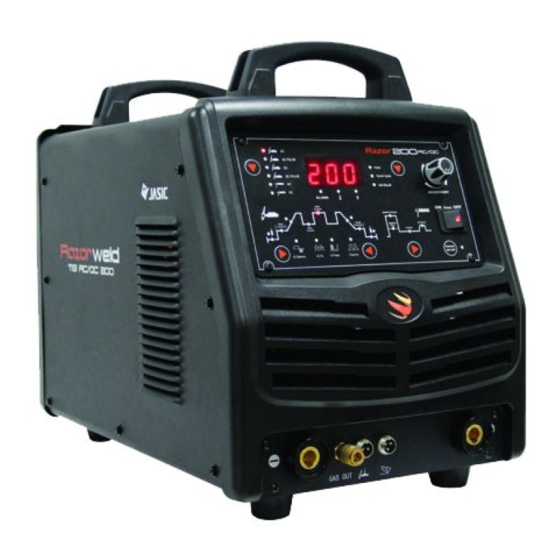
Machine Layout Description Razorweld ™ ™ Front Machine Layout Description 1. Control panel 2. Negative output socket 3. Torch gas connector outlet 4. Torch Switch Connector 5. Remote Foot Control Connector 6. Remote Torch Control Connector 7. Positive power connector 8. Mains switch 9. Adjustment control Rear Machine Layout Description 10. D ata Plate 10. Primary Input Power Lead 12. Gas Inlet Connector 13. Serial Number Plate... -
Page 9: Mode Select
Front Panel Operation - Weld Program Sequence Control Razorweld ™ ™ Front Panel Selector Keys AC PULSE Volts Torch Cycle DC PULSE Job Recall ADJUSTMENT ALARM Peak Power Current Ignition Current Start Finish Ignition Arc Force Current Current Time Base Current Current Remote... -
Page 10: Adjustment Encoder Knob
Front Panel Operation - Weld Program Sequence Control Razorweld ™ ™ Adjustment Encoder Knob - provides digital adjustment of welding parameters and weld selection cycles ADJUSTMENT The Adjustment Encoder Knob is used to set the value of the parameters required. Turning the encoder will adjust the value shown in the digital display screen. Power Arc Force Voltage Display Selector: When selected shows the output voltage on the digital display. Torch Cycle Selector: Controls the on/off cycle of the machine using the torch switch while incorporating the weld program parameters selections. Remote ON/OFF Job Recall Selector: Allows the setting and recall of welding parameters. -
Page 11: Torch Cycle Select
AC PULSE Volts Front Panel Operation - Weld Program Sequence Control Razorweld Torch C ™ ™ DC PULSE Job Rec Weld Program - Provides selection weld program parameters ALARM Parameter selection: Select by pushing selector pad to Peak Current cycle through to illuminate the icon of the parameter Ignition Cur required. Each push of the selector pad will move the icon illumination in a clockwise cycle. -
Page 12: Base Current
AC PULSE Volts Front Panel Operation - Weld Program Sequence Control Razorweld Torch Cycle DC PULSE ™ ™ Job Recall ADJUSTMENT Base Current - Provides selection for the Base Amperage during the Pulse Welding cycle. ALARM Peak Power Current Ignition Current AC PULSE Start Finish Ignition Arc Force Current Current Time Base Volts... -
Page 13: Post Gas
AC PULSE Volts Front Panel Operation - Weld Program Sequence Control Razorweld Torch Cycle DC PULSE ™ ™ Job Recall ADJUSTMENT Post Gas Timer - Provides selection for continued gas flow time at the end of the welding after the arc is out. ALARM Peak Power Current Ignition Current AC PULSE Start Finish Ignition Arc Force Current Current Time Base... -
Page 14: Ignition Current
Torch Cycle DC PULSE Job Recall ADJUSTMENT Front Panel Operation - Weld Program Sequence Control Razorweld ALARM ™ ™ Peak Power Current Ignition Current AC Balance - Provides setting of the % of on time of the electrode negative portion of the AC Wave output current. AC PULSE Start Finish Ignition Arc Force Current Current Time Base Current Current Volts Torch Cycle... -
Page 15: Arc Force
Volts Torch Cycle Front Panel Operation - Weld Program Sequence Control Razorweld Job Recall ™ ™ ADJUSTMENT Current - Provides setting of the main welding current (amps) delivered in MMA Mode (stick electrode). Power Ignition Current Finish Arc Force Ignition Current Time Current Volts Torch Cycle Remote Job Recall ON/OFF ADJUSTMENT ALARM Current: The value selected is shown in the Select by pushing selector key Turn the Encoder Knob... - Page 16 Front Panel Operation - LED Display Functions - Alarms Razorweld ™ ™ LED Display Functions - Alarms : Provides display of parameters and alarm codes. Parameter Display - Provides display of parameter settings. AC PULSE AC PULSE Volts Volts Volts Torch Cycle Torch Cycle DC PULSE DC PULSE Torch Cycle Job Recall Job Recall ADJUSTMENT...
- Page 17 Front Panel Operation - LED Display Functions - Alarms Razorweld ™ ™ AC PULSE AC PULSE Volts Volts Torch Cycle Torch Cycle DC PULSE DC PULSE Job Recall Job Recall ADJUSTMENT ADJUSTMENT ALARM ALARM Peak Peak Power Power Current Current Alarm E-3 Alarm E-4 : Indicates the machine...
- Page 18 Set Up Procedure for MMA (Stick) Welding: Razorweld ™ ™ MMA (Stick Electrode) Welding Set and Operation (1) Connecting the Welding Lead Set: Various electrodes require a different polarity for optimum results refer to the electrode manufacturers information for the correct polarity. Most GP electrodes are Electrode connected to output socket, Earth Connected to the output socket (2) Turn the power source on using the on/off switch located on the front control panel. (3) Select you preferred MMA mode using the MODE selector key. (3) Select preferred MMA mode using the MODE selector key (2) Turn on the Power source using the on/off switch at the rear of the machine (1) Connect the Earth Lead (1) Connect Electrode Lead lead to...
- Page 19 Set Up Procedure for MMA (Stick) Welding: Razorweld ™ ™ MMA - Ignition Time Set MMA - Arc Force Set. AC PULSE AC PULSE Volts Volts DC PULSE Torch Cycle Torch Cycle DC PULSE Job Recall Job Recall ADJUSTMENT ADJUSTMENT ALARM ALARM Peak...
- Page 20 MMA (Manual Metal Arc) Welding One of the most common types of arc welding is manual metal arc welding (MMA) or stick welding. An electric cur- rent is used to strike an arc between the base material and a consumable electrode rod or ‘stick’. The electrode rod is made of a material that is compatible with the base material being welded and is covered with a flux that gives off gaseous vapours that serve as a shielding gas and providing a layer of slag, both of which protect the weld area from atmospheric contamination. The electrode core itself acts as filler material the residue from the flux that forms a slag covering over the weld metal must be chipped away after welding. Core wire Flux coating Gas shield from flux melt Power Source Arc with core wire melt Flux residue forms slag cover Weld metal ▬ • The arc is initiated by momentarily touching the electrode to the base metal. Core wire • The heat of the arc melts the surface of the base metal to form a molten pool at the end of the electrode. Flux coating • The melted electrode metal is transferred across the arc into the molten pool and becomes the deposited weld metal. Base metal • The deposit is covered and protected by a slag which comes from the electrode coating. • The arc and the immediate area are enveloped by an atmosphere of protective gas Protective gas Manual metal arc ( stick) electrodes have a solid metal wire core and a flux coating. These electrodes are identified by the wire diameter and by...
-
Page 21: Mma (Stick) Welding Fundamentals
MMA (Stick) Welding Fundamentals Electrode Selection As a general rule, the selection of an electrode is straight forward,in that it is only a matter of selecting an electrode of similar composition to the parent metal. However, for some metals there is a choice of several electrodes, each of which has particular properties to suit specific classes of work. It is recommend to con- sult your welding supplier for the correct selection of electrode. Electrode Size The size of the electrode generally depends on the Average Thickness Maximum Recommended thickness of the section being welded, and the thicker of Material Electrode Diameter the section the larger the electrode required. The table 1.0 - 2.0mm 2.5mm gives the maximum size of electrodes that maybe used 2.0 - 5.0mm 3.2mm for various thicknesses of section base on using a gen- 5.0 - 8.0mm 4.0mm eral purpose type 6013 electrode. 8.0 - > mm 5.0mm Welding Current (Amperage) Correct current selection for a particular job is an im- Electrode Size Current Range portant factor in arc welding. With the current set too ø... - Page 22 Set Up Procedure for DC TIG Welding: Razorweld ™ ™ TIG Welding Set and Operation (1) Turn on the machine using the ON/OFF switch (2) Select the preferred TIG function with the MODE selector switch (3) Connect the TIG Torch connector to the negative terminal and tighten it (4) Connect the Earth Cable connector into the positive terminal and tighten it (5) Connect the torch switch remote lead into the torch remote socket (6) Insert the torch gas connector into the quick lock gas receptacle...
- Page 23 DC HF TIG Welding Standard Operation: Razorweld ™ ™ HF (high frequency) ignition allows the arc to be started in TIG welding without touching the tungsten to the work piece. By pressing the torch switch the machine will activate the gas flow and the HF ignition resulting in the arc igniting across the gap between the tungsten electrode and the work piece. The distance between the electrode and the work piece can be up to 5mm. This arc ignition method prevents tungsten inclusion in the work piece, promotes longer tungsten life and offers better operator control over the starting and stopping the arc. (1) Assemble the front end torch parts use the correct size and type of tungsten electrode for the job, the tungsten electrode requires a sharpened point for DC welding. (2) Select DC TIG and choose 2T or 4T trigger function preferred as per the descriptions below 2T Selection provides 2 times function of the torch switch. (1) Pressing the torch switch gives arc ignition and initializes the welding current and the welding current is maintained by the torch remaining on.
- Page 24 DC TIG Welding The DC power source uses what is known as DC (direct current) in which the main electrical component known as electrons flow in only one direction from the negative pole (terminal) to the positive pole (terminal). In the DC electrical circuit there is an electrical principle at work which should always be taken into account when using any DC circuit. With a DC circuit 70% of the energy (heat) is always on the positive side. This needs to be understood because it determines what terminal the TIG torch will be connected to (this rule applies to all the other forms of DC welding as well ). DC TIG welding is a process in which an arc is struck between a TUNGSTEN electrode and the metal work piece. The weld area argon gas is shielded by an inert gas flow to prevent contamination of the...
-
Page 25: Tig Welding With Filler Wire Technique
TIG Welding Fusion Technique Manual TIG welding is often considered the most difficult of all the welding processes. Because the welder must maintain a short arc length, great care and skill are required to prevent contact between the electrode and the work piece. Similar to Oxygen Acetylene torch welding, TIG welding normally requires two hands and in most instances requires the welder to manually feed a filler wire into the weld pool with one hand while manipulating the welding torch in the other. However, some welds combining thin materials can be accomplished without filler metal like edge, corner, and butt joints. This is known as Fusion welding where the edges of the metal pieces are melted together using only the heat and arc force generated by the TIG arc. Once the arc is started the torch tungsten is held in place until a weld pool is created, a circular movement of the tungsten will assist is creating a weld pool of the desired ° angle and move smoothly and evenly size. Once the weld pool is established tilt the torch at about a 75 along the joint while fusing the materials together. 75°... - Page 26 DC Pulse TIG Welding Pulse TIG welding is when the current output (amperage) changes between high and low current. Electronics within the welding machine create the pulse cycle. Welding is done during the high-amperage interval (this high amperage is referred to as peak current). During the low amperage period, the arc is maintained but the current output of the arc is reduced (this low amperage is referred to as base current). During pulse welding the weld pool cools during the low amperage period. This allows a lower overall heat input into the base metal. It allows for controlled heating and cooling periods during welding providing better control of heat input, weld penetration, operator control and weld appearance. There are 4 variables within the pulse cycle: Peak Current - Base Current - Pulse Frequency - Pulse Width Setting and manipulation of these variables will determine the nature of the weld current output and is at the discretion of the operator. Peak Current is the main welding current (amps) set to melt the material being welded and works much the same as setting maximum amperage values for regular DC TIG: as a guide use 30-40 amps for every 1mm of material thickness.
- Page 27 Set up and operation for DC PULSE TIG Welding The Razorweld 200 machine has digital pulse frequency control. All the parameters for DC Pulse TIG welding - Peak Amp, Base Amp, Pulse Frequency and Pulse Width are easy to set via the digital control panel. EXAMPLE OF PULSE DC TIG WELDING - SETUP PARAMETERS: Material = Stainless Steel x 2.0mm / Tungsten Electrode = 1.6mm 2% Thoriated / Gas = Argon AC PULSE The following steps are a guide as a starting point for you to set the machine up in Pulse mode to give an Volts example of welding in Pulse mode function. You can experiment by changing any of the variables to see...
- Page 28 Set Up Procedure for AC TIG Welding: Razorweld ™ ™ TIG Welding Set and Operation (1) Turn on the machine using the ON/OFF switch (2) Select the preferred TIG function with the MODE selector switch (3) Connect the TIG Torch connector to the negative terminal and tighten it (4) Connect the Earth Cable connector into the positive terminal and tighten it (5) Connect the torch switch remote lead into the torch remote socket (6) Insert the torch gas connector into the quick lock gas receptacle...
- Page 29 AC HF TIG Welding Standard Operation: Razorweld ™ ™ AC (alternating current) enables us to TIG weld non ferrous alloys like Aluminium, Aluminium Alloys and Magnesium. These materials have an insulating surface oxide layer that melts at a higher temperature than the base metal making it difficult to weld the base metal if the oxides are not removed. AC welding current is ideal because the nature of the AC wave form assists in breaking the surface oxide layer. HF arc igni- tion provides easy and precise starting of the arc. (8) Assemble the front end torch parts use the correct size and type of tungsten electrode for the job. (9) Select AC tig function using the mode selection key (10) Choose 2T or 4T trigger function preferred as per the descriptions below 2T Selection provides 2 times function of the torch switch. (1) Pressing the torch switch gives arc ignition and initializes the welding current and the welding current is maintained by the torch remaining on.
-
Page 30: Ac Wave Balance Control
AC TIG Welding - AC Wave Balance Control AC (alternating current) enables us to TIG weld non ferrous alloys like Aluminium, Magnesium and Alumin- ium Alloys. These materials have an insulating surface oxide layer that melts at a higher temperature than the base metal making it difficult to weld the base metal if the oxides are not removed. AC welding current is ideal because the nature of the AC wave form assists in breaking the surface oxide layer. AC (alternating current) has a current cycle that flows from + (direct) polarity to - (reverse) polarity. The reversing of the polarity breaks the surface oxide while the direct polarity melts the base material. direct polarity current reverse polarity There are inherent problems that come with AC TIG arc rectification, arc stutter, arc wandering and arc stoppage. These problems typically occur during the transition between + and - cycles. The current is less (30%) during the half of the cycle when the electrode is positive and there is a resist- ance of the electron flow during this half cycle (rectification). The lack of current flow during this half cycle makes the AC arc unstable. direct polarity current reverse polarity To overcome this lack of flow during one half of the cycle, a high-frequency (HF) voltage is generated and fed into the welding circuit. The HF maintains the arc stability during the half cycle when the electrode is positive. UNBALANCED WAVE FORM direct polarity current reverse polarity High-frequency voltage flows continually in the welding circuit and keeps the shielding arc in the welding area in an ionized state. When the arc is ionized the arc is maintained during the half of the cycle when the electrode is positive. However while the arc is maintained less current flows during this half of the AC cycle,... - Page 31 AC TIG Welding - AC Wave Balance Control In older machines, a balanced current output wave was achieved using a large number of capacitors in series or a battery in the welding circuit. Modern TIG power sources use electronics to create and maintain a balanced wave and now most AC TIG power sources produce a square wave current output. direct polarity current reverse polarity A square wave power supply can change the current from electrode + positive to electrode - negative very quickly. This produces high voltage as the current switches polarities allowing the arc to restart easily. The arc can be maintained without the use of high-frequency or any other arc stabilising methods. LESS POSITIVE MORE POSITIVE EVEN BALANCE BALANCED SQUARE WAVE FORM BALANCE BALANCE direct polarity current reverse polarity Even Penetration - Stable Arc More Penetration - Faster Welding Less Penetration - Oxide Cleaning More Electrode Capacity...
- Page 32 AC PULSE Volts Set up and operation for AC PULSE TIG Welding Torch Cycle DC PULSE Job Recall ADJUSTMENT ALARM Peak Power Current Ignition Current C PULSE Start Finish Ignition Arc Force Current Current Time Base Volts Current Current Torch Cycle C PULSE AC PULSE Job Recall...
- Page 33 Set up and operation for AC PULSE TIG Welding The Razorweld 200ACDC machine has digital pulse frequency control. All the parameters for AC & DC Pulse TIG welding - Peak Amp, Base Amp, Pulse Frequency and Pulse Width are easy to set via the digital control panel. EXAMPLE OF PULSE AC TIG WELDING - SETUP PARAMETERS: Material = Aluminium x 3.0mm / Tungsten Electrode = 2.4mm Zirconiated / Gas = Argon (1) Prepare the machine for AC TIG welding as per the AC TIG operating guide on page Set the Peak Current at 150 Amps AC PULSE Set the Base Current around 40% (Base Current is % of the Peak Current eg 40% of 150 = 60 Amps) Volts...
- Page 34 AC TIG Welding - AC Wave Balance Control It is possible with the RAZOR200ACDC machine to adjust the frequency of the AC Square Wave output. It means that the amount of time that it takes the AC square wave to complete a full cycle switch from postive (+) to negative (-) can be adjusted from 20 Hz (20 times per second) to 70 Hz Increasing frequency (Hz) causes the current to change direction more often, which means that it spends less time per cycle in both DC electrode negative and DC electrode positive mode. By spending less time at each polarity, the arc cone has less time to expand. A higher frequency produces a narrower arc cone producing an arc that is tighter with more focus at the exact spot the electrode is pointing. The result is improved arc stability, ideal for fillet welds and other fit ups requiring precise penetration. Decreasing the frequency softens the arc and broadens the weld pool producing a wider bead, produces good overall penetration and ideal for build up applications. AC Square Wave Current 20Hz 70Hz Frequency Adjustment Low AC Square Wave Hz Wider Cleaning Action Wider Weld Bead Wider Arc Broader Weld Pool High AC Square Wave Hz Narrower Cleaning Action Narrower Weld Bead...
-
Page 35: Remote Amperage Controls
Remote Amperage Controls AC PULSE Volts Remote amperage controls allow for the welding current to adjusted remotely from the welding machine Torch Cycle DC PULSE during welding. Job Recall ADJUSTMENT Remote Foot Amp Control Connection ALARM Peak Power Current Ignition Current Start Finish Arc Force Ignition Current Current Time Base Current Current Remote AC Balance AC Hz % Pulse Pulse Hz... -
Page 36: Tungsten Electrodes
Tungsten Electrodes Tungsten is a rare metallic element used for manufacturing TIG welding electrodes. The TIG process relies on tung- sten’s hardness and high-temperature resistance to carry the welding current to the arc. Tungsten has the highest melting point of any metal, 3,410 degrees Celsius. Tungsten electrodes are nonconsumable and come in a variety of sizes, they are made from pure tungsten or an al- loy of tungsten and other rare earth elements. Choosing the correct tungsten depends on the material being welded, the amount of amps required and whether you are using AC or DC welding current. Tungsten electrodes are colour-coded at the end for easy identification. Below are the most commonly used tungsten electrodes found in the New Zealand and Australian market. Thoriated Thoriated tungsten electrodes (AWS classification EWTh-2) contain a minimum of 97.30 percent tungsten and 1.70 to 2.20 percent thorium and are called 2 percent thoriated. They are the most commonly used electrodes today and are preferred for their longevity and ease of use. Thorium increases the electron emission qualities of the electrode, which improves arc starts and allows for a higher current-carrying capacity. This electrode operates far below its melt- ing temperature, which results in a considerably lower rate of consumption and eliminates arc wandering for greater stability. Compared with other electrodes, thoriated electrodes deposit less tungsten into the weld puddle, so they cause less weld contamination. Thorium however is a low-level radioactive hazard and many users have switched to other alternatives. Regard- ing the radioactivity, thorium is an alpha emitter but when it is enclosed in a tungsten matrix the risks are negligible. Thus holding a stick of Thoriated tungsten in your hand should not pose a great threat unless a welder has open cuts on their skin. Thoriated tungsten should not get in contact with open cuts or wounds. The more significant danger to welders can occur when thorium oxide gets into the lungs. This can happen from the exposure to vapours during welding or from ingestion of material/dust in the grinding of the tungsten. Follow the manufacturer’s warnings, instruc- tions, and the Material Safety Data Sheet (MSDS) for its use. Ceriated (Color Code: Orange) Ceriated tungsten electrodes (AWS classification EWCe-2) contain a minimum of 97.30 percent tungsten and 1.80 to 2.20 percent cerium and are referred to as 2 percent ceriated. Ceriated tungstens perform best in DC welding at low current settings. They have excellent arc starts at low amperages and become popular in such applications as orbital tube welding, thin sheet metal work. They are best used to weld carbon steel, stainless steel, nickel alloys, and titanium, and in some cases it can replace 2 percent thoriated electrodes. Ceriated tungsten is best suited for lower amperages it should last longer than Thoriated tungsten higher amperage applications are best left to Thoriated or Lanthanated tungsten. Lanthanated (Color Code: Gold) Lanthanated tungsten electrodes (AWS classification EWLa-1.5) contain a minimum of 97.80 percent tungsten and 1.30 percent to 1.70 percent lanthanum, and are known as 1.5 percent lanthanated. These electrodes have excellent arc starting, a low burn off rate, good arc stability, and excellent re-ignition characteristics. Lanthanated tungstens also share the conductivity characteristics of 2 percent thoriated tungsten. Lanthanated tungsten electrodes are ideal if you want to optimise your welding capabilities. They work well on AC or DC electrode negative with a pointed end, or they can be balled for use with AC sine wave power sources. Lanthanated tungsten maintains a sharpened point... - Page 37 Tungsten Preparation Always use wheels when grinding and cutting. While tungsten is a very hard material, the surface of a DIAMOND diamond wheel is harder, and this makes for smooth grinding. Grinding without diamond wheels, such as aluminium oxide wheels, can lead to jagged edges, imperfections, or poor surface finishes not visible to the eye that will contrib- ute to weld inconsistency and weld defects. Always ensure to grind the tungsten in a longitudinal direction on the grinding wheel. Tungsten electrodes are manu- factured with the molecular structure of the grain running lengthwise and thus grinding crosswise is “grinding against the grain.” If electrodes are ground crosswise, the electrons have to jump across the grinding marks and the arc can start before the tip and wander. Grinding longitudinally with the grain, the electrons flow steadily and easily to the end of the tungsten tip. The arc starts straight and remains narrow, concentrated, and stable. grind longitudinal on the don’t grind across grinding wheel the grinding whee Electrode Tip/Flat The shape of the tungsten electrode tip is an important process variable in precision arc welding. A good selection of tip/flat size will balance the need for several advantages. The bigger the flat, the more likely arc wander will occur and the more difficult it will be to arc start. However, increasing the flat to the maximum level that still allows arc start and eliminates arc wonder will improve the weld penetration and increase the electrode life. Some welders still grind electrodes to a sharp point, which makes arc starting easier. However, they risk decreased welding performance from melting at the tip and the possibility of the point falling off into the weld pool. 2.5 times tungsten diameter pointed tip flat tip Electrode Included Angle/Taper - DC Welding Tungsten electrodes for DC welding should be ground longitudinally and concentrically with diamond wheels to a specific included angle in conjunction with the tip/flat preparation. Different angles produce different arc shapes and offer different weld penetration capabilities. In general, blunter electrodes that have a larger included angle provide...
- Page 38 Suregrip Series SR26 ERGO TIG TORCH 180A AIR COOLED TIG WELDING TORCH Rating:180Amp DC, 125Amp AC @35% duty cycle. Wear Parts Identification Next Page Torch Model Description Part Number SR26 Suregrip Tig Torch Package c/w QF Gas Connect SR-26-4MCP50 SR-26-8MCP50 Spare Parts Part Number Description...
- Page 39 Suregrip Series SR26 ERGO TIG TORCH Standard Front End Parts Part # Description Part # Description Part # Description 18CG Cup Gasket 10N30 Collet Body 1.0mm 10N49L Long Alumina Nozzle Ø 8mm #5L 10N31 Collet Body 1.6mm 53N48L Long Alumina Nozzle Ø 10mm #6L 10N32 Collet Body 2.4mm 53N47L...
- Page 40 TIG WELDING TROUBLE SHOOTING The following chart addresses some of the common problems of TIG welding. In all cases of equipment malfunction, the manufacturer’s recommendations should be strictly adhered to and followed. 1: Tungsten burning away quickly Possible Reason Suggested Remedy Incorrect Gas Check that pure Argon is being used No gas Check the gas cylinder contains gas and is connected Inadequate gas flow Check the gas is connected, check hoses, gas valve and torch are not restricted. Set the gas flow between 10 - 15 l/min flow rate Back cap not fitted correctly Make sure the torch back cap is fitted so that the o-ring is inside the torch body Torch connected to DC + Connect the torch to the DC- output terminal Incorrect tungsten being used Check and change the tungsten type if necessary...
- Page 41 continued- TIG WELDING TROUBLE SHOOTING 7: Arc wanders during DC welding Possible Reason Suggested Remedy Poor gas flow Check and set the gas flow between 10 - 15 l/min flow rate Incorrect arc length Lower torch so that the tungsten is off of the work piece 2 - 5mm Tungsten incorrect or in poor condi- Check that correct type of tungsten is being used. Remove 10mm from the weld end of tion the tungsten and re sharpen the tungsten Poorly prepared tungsten Grind marks should run lengthwise with tungsten, not circular. Use proper grinding method and wheel.
- Page 42 MMA (Stick) WELDING TROUBLE SHOOTING The following chart addresses some of the common problems of MMA welding. In all cases of equipment malfunction, the manufacturer’s recommendations should be strictly adhered to and followed. 1: No arc Possible Reason Suggested Remedy Incomplete welding circuit Check earth lead is connected. Check all cable connections. Wrong mode selected Check the MMA selector switch is selected No power supply Check that the machine is switched on and has a power supply 2: Porosity −...
- Page 43 Fax: (02) 9780 4244 Welding Guns Of Australia Pty Ltd Email: sales@unimig.com.au / Web: www.unimig.com.au ABN: 14 001 804 422 Welding Guns Of Australia Pty Ltd (‘Us’, ‘We’) warrants that the following products under UNI-MIG, UNI-TIG, UNI-PLAS, UNI-FLAME, TECNA, T&R, HIT-8SS & ROTA, supplied by Us and purchased by you from an Authorised UNI-MIG, UNI-TIG, UNI-PLAS, UNI-FLAME, TECNA, T&R, HIT-8SS &...
- Page 44 WARRANTY / RETURNS / EXCHANGES We understand that sometimes you may need to return a product you have purchased from Welding Guns Of Australia PTY LTD Authorised Dealer Network, to assist you, we have set out below the Welding Guns Of Australia PTY LTD Returns Policy that you should know.
- Page 45 WARRANTY EXCLUSIONS This Warranty covers Material and Faulty Workmanship defects only. This Warranty does not cover damage caused by: • Normal wear and tear due to usage • Misuse or abusive use of the UNI-MIG, UNI-TIG, UNI-PLAS, UNI-FLAME, TECNA, T&R, HIT-8SS & ROTA, instructions supplied with the product.
- Page 48 Welding Guns Of Australia PTY LTD 2013 Welding Guns Of Australia Pty Ltd ABN: 14 001 804 422 PO Box 3033, Lansvale NSW 2166, AUSTRALIA 112 Christina Rd, Villawood, NSW 2163 Phone: (02) 9780 4200 Fax: (02) 9780 4244 Email: sales@unimig.com.au / Web: www.unimig.com.au...
Need help?
Do you have a question about the KUMJRRW200AC/DC and is the answer not in the manual?
Questions and answers