Table of Contents
Advertisement
Quick Links
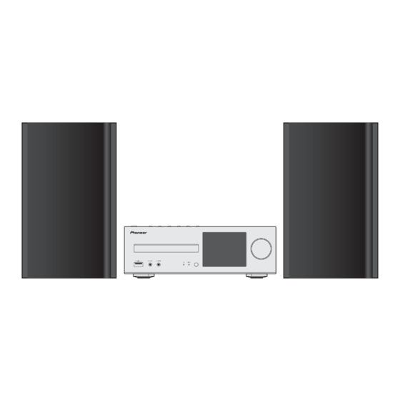
NETWORK CD RECEIVER SYSTEM
X-HM82-K
X-HM82-S
X-HM72-K,-S X-HM72D-K,-S
NETWORK CD RECEIVER
XC-HM82-K,-S
XC-HM82D-K
SPEAKER SECTION
S-HM82GB,S-HM82SA,S-HM72
THIS MANUAL IS APPLICABLE TO THE FOLLOWING MODEL(S) AND TYPE(S).
Model
Type
X-HM82-K, -S
SYXEV8
X-HM82-S
AXEV5
X-HM82D-K
VXEV8
XC-HM82-K, -S
SYXEV8
XC-HM82-K
CXEV
XC-HM82D-K
VXEV8
X-HM72-K, -S
SYXEV8
X-HM72D-K
VXEV8
X-HM72D-S
YXEV8
S-HM82GB
SYXEV8
S-HM82GB
VXEV8
S-HM82SA
AXEV5
S-HM72
SYXEV8
S-HM72
YXEV8
S-HM72
VXEV8
PIONEER CORPORATION
PIONEER ELECTRONICS (USA) INC. P.O. Box 1760, Long Beach, CA 90801-1760, U.S.A.
PIONEER EUROPE NV Haven 1087, Keetberglaan 1, 9120 Melsele, Belgium
PIONEER ELECTRONICS ASIACENTRE PTE. LTD. 253 Alexandra Road, #04-01, Singapore 159936
PIONEER CORPORATION 2014
Power Requirement
AC 220 V to 230 V
AC 220 V to 230 V
AC 220 V to 230 V
AC 220 V to 230 V
AC 120 V
AC 220 V to 230 V
AC 220 V to 230 V
AC 220 V to 230 V
AC 220 V to 230 V
1-1, Shin-ogura, Saiwai-ku, Kawasaki-shi, Kanagawa 212-0031, Japan
X-HM82-K
X-HM82D-K
Serial No.
&&&&######YY
&&&&######CN
&&&&######GB
&&&&######YY
&&&&######UC
&&&&######GB
&&&&######YY
&&&&######GB
&&&&######YY
ORDER NO.
RRV4574
Remarks
YY:Europe
CN:China
GB:U.K
YY:Europe
UC:North America
GB:U.K
YY:Europe
GB:U.K
YY:Europe
K-FZV OCT.
2014 Printed in Japan
Advertisement
Table of Contents

Summarization of Contents
Safety Information
Warning
Product may contain chemicals known to cause cancer or reproductive harm.
Label Check
Describes caution labels on the unit, specifically laser warnings.
Service Precautions
Notes on Soldering
Guidance on using lead-free solder and proper soldering iron temperatures.
Diagnosis
Troubleshooting
Step-by-step guide for diagnosing and resolving common issues like 'No power'.
Protection Circuit
Explains protection functions (DC, POWER, AMP, OVER TEMP, PWM) and their LED indications.
Service Mode
How to Enter Service Mode
Procedure to access the dedicated service menu using the remote control.
Protect Check Mode
Displays detected protection activations and allows resetting counters.
Disassembly
Discharge
Steps to safely discharge the unit before diagnosis, involving short-circuiting capacitors.
Each Setting and Adjustment
Updating of the Firmware
Guide for updating firmware for MAIN, Subcom, BCO, CD I/F, and CD DSP microcomputers.
Schematic Diagram
Main Assy (1/4)
Schematic diagram for the Main Assembly, section 1 of 4.
PCB Parts List
List of Assemblies
Comprehensive list of assemblies with part numbers for different models.


Need help?
Do you have a question about the S-HM82GB and is the answer not in the manual?
Questions and answers