Table of Contents
Advertisement
Instruction manual J4C 20 - 300
CONTENT
INTRODUCTION .....................................................................................................................................02
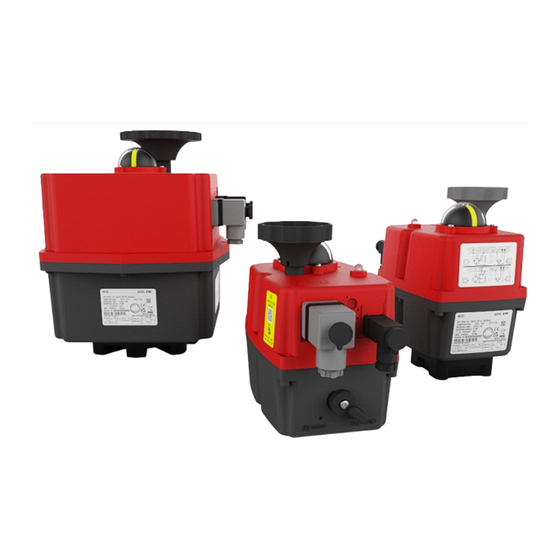
OVERVIEW ..............................................................................................................................................02
ELECTRIC CONNECTION ......................................................................................................................03
WIRING DIAGRAM STANDARD OPEN/CLOSE ...................................................................................04
WIRING DIAGRAM OPTION DPS POSITIONER..................................................................................05
WIRING DIAGRAM OPTION 3 POSITIONS .........................................................................................05
WIRING DIAGRAM OPTION PERMANENT PHASE ...........................................................................05
END POSITION FEEDBACK ..................................................................................................................06
POSITION INDICATOR ..........................................................................................................................06
MANUAL OVERRIDE ..............................................................................................................................07
AUTOMATIC HEATER ............................................................................................................................07
TORQUE LIMITER ..................................................................................................................................07
STATUS LED ...........................................................................................................................................07
STATUS LED SIGNALS OPEN/CLOSE .................................................................................................08
STATUS LED SIGNALS DPS .................................................................................................................08
MOUNTING ON VALVE ..........................................................................................................................09
OPEN HOUSING .....................................................................................................................................09
CAM ADJUSTMENT ..............................................................................................................................09
OPTION BSR BATTERY SAFETY PACK ...............................................................................................10
OPTION DPS POSITIONER ...................................................................................................................11
GENERAL TECHNICAL DATA ...............................................................................................................12
Advertisement
Table of Contents

Related Manuals for J4C S85


Summary of Contents for J4C S85
-
Page 1: Table Of Contents
Instruction manual J4C 20 - 300 CONTENT INTRODUCTION .............................02 OVERVIEW ..............................02 ELECTRIC CONNECTION ........................03 WIRING DIAGRAM STANDARD OPEN/CLOSE ...................04 WIRING DIAGRAM OPTION DPS POSITIONER..................05 WIRING DIAGRAM OPTION 3 POSITIONS ..................05 WIRING DIAGRAM OPTION PERMANENT PHASE ................05 END POSITION FEEDBACK ........................06 POSITION INDICATOR ..........................06... -
Page 2: Introduction
(ENGLISH) J4C 20 to 300 INSTRUCTION MANUAL 2 Read these instructions carefully before putting the appliance into operation. Damage caused by non-compliance with these instructions is not covered by the warranty/guarantee. When operating electrical devices, certain parts of these devices inevitably carry dangerous voltages. -
Page 3: Electric Connection
Models S20 to S300 can be operated in the range 24V-240V DC/AC (50/60Hz) -0%/+5% • Models B20 to B300 can be operated in the range 12V DC/AC (50/60Hz) -0%/+5% POWER CONSUMTION The actuator protects itself against increased current consumption, so that fusing is only necessary as line protection. -
Page 4: Wiring Diagram Standard Open/Close
(ENGLISH) J4C 20 to 300 INSTRUCTION MANUAL 4 Wiring diagram Open/Close In the standard version, all of these three listed wiring variants can be used without further configuration. OPEN-CLOSE AC/DC = Supply plug (Grey) = End position plug (Black) Neutral / - PIN 1 & Phase / + PIN 2 = CLOSE Com PIN 1 &... -
Page 5: Wiring Diagram Option Dps Positioner
(ENGLISH) J4C 20 to 300 INSTRUCTION MANUAL 5 Wiring diagram Option DPS Positioner Caution! Earth pin must not be connected to DPS connector (C), as this could trigger a self adjustment. = Supply plug (Grey) = DPS plug (black) = End position plug (Black) Neutral / - PIN 1 &... -
Page 6: End Position Feedback
Please refer to the circuit diagram on the respective device. Position indicator All J4C quarter-turn actuators are equipped with an optical position indicator consisting of a black base with a yellow insert. It indicates the actual position and working direction. -
Page 7: Manual Override
J4C 20 to 300 INSTRUCTION MANUAL 7 Manual override All J4C actuators have a manual override to move the valve to the desired position in case of an emergency. The operating mode can be set via the manual override switch:... -
Page 8: Status Led Signals Open/Close
(ENGLISH) J4C 20 to 300 INSTRUCTION MANUAL 8 OPERATING STATUS OPEN/CLOSE ACTUATOR LED STATUS Actuator without power supply Actuator is in opened position Actuator is in closed position Actuator in stop position ( Open + Close simultaneously controlled. Only for standard wiring) -
Page 9: Mounting On Valve
(ENGLISH) J4C 20 to 300 INSTRUCTION MANUAL 9 Mounting on valve The torque of the valve should never exceed the working torque of the actuator, taking into account the specific application and after multiplying by a sufficient safety factor. Before installation, components that could block the valve (e.g. -
Page 10: Option Bsr Battery Safety Pack
(ENGLISH) J4C 20 to 300 INSTRUCTION MANUAL 10 Option BSR battery safety pack With the BSR, the actuator moves to its specified safety position (NC or NO) in the event of a power failure. The safety function is realised via an internal rechargeable battery, therefore the actuator must be permanently supplied with power! The battery is supplied pre-charged;... -
Page 11: Option Dps Positioner
(ENGLISH) J4C 20 to 300 INSTRUCTION MANUAL 11 Option DPS Positioner With the DPS, the part-turn actuator can be freely positioned in its working range via the input signal. In addition, it permanently provides its actual position as an output signal. -
Page 12: General Technical Data
Technical data Model size Working torque 20 Nm 35 Nm 55 Nm 85 Nm 140 Nm 300 Nm Break torque 25 Nm 38 Nm 60 Nm 90 Nm 170 Nm 350 Nm Working time without load 13 s 29 s 34 s 58 s (5 s, 140 s)
Need help?
Do you have a question about the S85 and is the answer not in the manual?
Questions and answers