Table of Contents
Advertisement
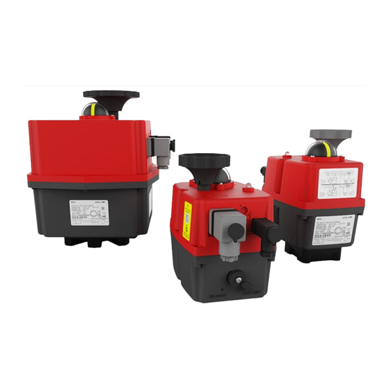
Instruction manual J4C 20 - 300
CONTENT
INTRODUCTION .....................................................................................................................................02
OVERVIEW ..............................................................................................................................................02
ELECTRIC CONNECTION ......................................................................................................................03
WIRING DIAGRAM STANDARD OPEN/CLOSE ...................................................................................04
WIRING DIAGRAM OPTION DPS POSITIONER..................................................................................05
WIRING DIAGRAM OPTION 3 POSITIONS .........................................................................................05
WIRING DIAGRAM OPTION PERMANENT PHASE ...........................................................................05
END POSITION FEEDBACK ..................................................................................................................06
POSITION INDICATOR ..........................................................................................................................06
MANUAL OVERRIDE ..............................................................................................................................07
AUTOMATIC HEATER ............................................................................................................................07
TORQUE LIMITER ..................................................................................................................................07
STATUS LED ...........................................................................................................................................07
STATUS LED SIGNALS OPEN/CLOSE .................................................................................................08
STATUS LED SIGNALS DPS .................................................................................................................08
MOUNTING ON VALVE ..........................................................................................................................09
OPEN HOUSING .....................................................................................................................................09
CAM ADJUSTMENT ..............................................................................................................................09
OPTION BSR BATTERY SAFETY PACK ...............................................................................................10
OPTION DPS POSITIONER ...................................................................................................................11
GENERAL TECHNICAL DATA ...............................................................................................................12
Advertisement
Table of Contents

Related Manuals for J4C S35


Summarization of Contents
Introduction
Environment
The internal heater protects against condensation; outdoor use requires protection against climatic influences.
Maintenance
No maintenance is required, but regular functional checks are recommended for safety.
Electric Connection
Voltage
Actuators automatically recognize operating voltage within specified ranges for S20-S300 and B20-B300 models.
Power Consumption
Actuator has internal power supply unit; external fuse with appropriate tripping characteristics is recommended.
Connection Plugs
Details on DIN plugs and cable diameter requirements for connection, with caution on seal installation.
Wiring Diagrams
Standard Open/Close
Wiring diagrams for standard Open/Close, Open-Close-Stop, and 2-wire DC Open/Close configurations.
Wiring Diagram Options
Option DPS Positioner
Wiring diagram for actuators with the DPS Positioner option, including input/output signal configurations.
Option 3 Positions
Wiring diagram for actuators with the 3 Positions option, showing connections for OPEN, CLOSE, and MIDDLE states.
Option Permanent Phase
Wiring diagrams for Permanent phase NC (Normally Closed) and NO (Normally Open) configurations.
End Position Feedback
Gold Plated Microswitches
Details on using gold-plated microswitches for load-free monitoring of end positions to prevent failure at low currents.
Different Wiring Options
Information on different SPDT microswitch variants available, such as 4 potential-free end positions or 2x NC contacts.
Position Indicator
Optional Position Indicator
Describes an optional, freely configurable position indicator that can display different configurations or bore types.
Operating Status and LED Signals
Open/Close Actuator Status
Table detailing operating statuses and corresponding LED signals for the Open/Close actuator.
DPS Positioner Status
Table detailing operating statuses and corresponding LED signals for the DPS Positioner.
Mounting on Valve
Open Housing
Procedure for opening the housing to adjust working angle or configure DPS/BSR, requiring power off and plug removal.
Close Housing
Instructions for refitting the housing cover, ensuring seals and parts are correctly placed.
Adjustment Cam System
Details on setting working angle and end position feedback using the cam system and adjustment tool.
Option BSR Battery Safety Pack
Function Test
Procedure for a regular functional test (at least annually) to verify the BSR safety function.
Maintenance
Recommends battery replacement after 300 activations or 5 years for optimal BSR function.
Configuration NC / NO
Explains how to configure the safety position (NC or NO) using the 'SELDIR' jumper.
Option DPS Positioner
Adjusting the Working Angle
Describes how self-adjustment sets the working angle, requiring prior adjustment of the cam system.
Self Adjustment with Opened Cover
Step-by-step guide for self-adjustment with the housing opened, using dipswitches.
Self Adjustment from Outside
Procedure for external self-adjustment using the DPS plug and connecting Pin1 to Earth.
Signal Configuration
Details on setting signal types (4-20mA, 0-10V, 1-10V) and safety functions (NC/NO) via dip switches.
Need help?
Do you have a question about the S35 and is the answer not in the manual?
Questions and answers