Table of Contents
Advertisement
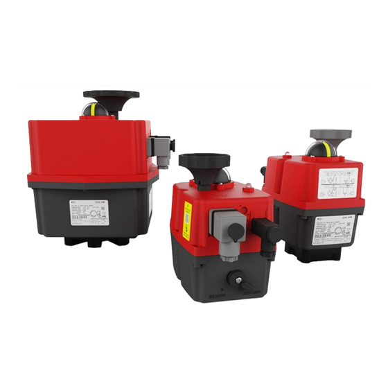
Instruction manual J4C 20 - 300
CONTENT
INTRODUCTION .....................................................................................................................................02
OVERVIEW ..............................................................................................................................................02
ELECTRIC CONNECTION ......................................................................................................................03
WIRING DIAGRAM STANDARD OPEN/CLOSE ...................................................................................04
WIRING DIAGRAM OPTION DPS POSITIONER..................................................................................05
WIRING DIAGRAM OPTION 3 POSITIONS .........................................................................................05
WIRING DIAGRAM OPTION PERMANENT PHASE ...........................................................................05
END POSITION FEEDBACK ..................................................................................................................06
POSITION INDICATOR ..........................................................................................................................06
MANUAL OVERRIDE ..............................................................................................................................07
AUTOMATIC HEATER ............................................................................................................................07
TORQUE LIMITER ..................................................................................................................................07
STATUS LED ...........................................................................................................................................07
STATUS LED SIGNALS OPEN/CLOSE .................................................................................................08
STATUS LED SIGNALS DPS .................................................................................................................08
MOUNTING ON VALVE ..........................................................................................................................09
OPEN HOUSING .....................................................................................................................................09
CAM ADJUSTMENT ..............................................................................................................................09
OPTION BSR BATTERY SAFETY PACK ...............................................................................................10
OPTION DPS POSITIONER ...................................................................................................................11
GENERAL TECHNICAL DATA ...............................................................................................................12
Advertisement
Table of Contents

Related Manuals for J4C S55


Summarization of Contents
INTRODUCTION
ENVIRONMENT
Discusses environmental factors like temperature and vibrations, and necessary protection measures.
MAINTENANCE
Outlines maintenance requirements and recommends regular functional checks for actuator reliability.
ELECTRIC CONNECTION
VOLTAGE
Specifies the available voltage ranges for different J4C actuator models (e.g., 24V, 110V, 230V).
POWER CONSUMTION
Explains power consumption and the need for appropriate external fuses or circuit breakers.
CONNECTION PLUGS
Describes the types of DIN connection plugs and the required cable diameter specifications.
Wiring diagram Open/Close
OPEN-CLOSE AC/DC
Wiring diagram for Open-Close operation using AC or DC power supply.
OPEN - CLOSE - STOP AC/DC
Wiring diagram for Open-Close-Stop operation with AC/DC power.
OPEN - CLOSE 2 WIRE DC
Wiring diagram for Open-Close operation using a 2-wire DC connection.
Wiring diagram Option DPS Positioner
Wiring diagram Option 3 Positions
Wiring diagram for actuators configured with a 3-position control functionality.
Wiring diagram Option Permanent phase
Wiring diagrams for actuators operating with permanent phase control (NC and NO).
End position feedback
Gold plated microswitches
Details the use and benefits of gold-plated microswitches for load-free end position monitoring.
Differen wiring optins
Covers alternative wiring options for microswitches, including 4 positions and changeover contacts.
Position indicator
Optional position indicator
Information on an optional, configurable position indicator for enhanced display capabilities.
Manual override
Heater
Explains the internal heater's role in preventing condensation and maintaining optimal operating temperature.
Torque limiter
Describes the torque limiter's function to protect against excess torque and valve blockage.
Status LED
Explains the function and meaning of the status LED for indicating actuator operating states.
Mounting on valve
Open housing
Steps for opening the actuator housing to access internal components for adjustment or configuration.
Close housing
Guidance on properly refitting the actuator housing cover, including seal and screw placement.
Adjustment cam system
Explains the cam system used for setting working angles and end position feedback.
Option BSR battery safety pack
Function test
Procedure for performing regular functional tests of the BSR battery safety pack.
Maintenance
Guidance on scheduled battery replacement for the BSR safety pack based on usage or time.
Configuration NC / NO
Instructions on how to configure the safety position (NC or NO) using the SELDIR jumper.
Option DPS Positioner
Adjusting the working angle
How to set the actuator's working angle using the self-adjustment feature.
Self adjustment with opened cover
Step-by-step guide for self-adjustment with the actuator housing opened.
Self adjustment from outside
Procedure for performing self-adjustment externally via the DPS plug.
Signal configuration
Instructions for configuring input signal types (e.g., 4-20mA, 0-10V) using dip switches.
Need help?
Do you have a question about the S55 and is the answer not in the manual?
Questions and answers