Table of Contents
Advertisement
Available languages
Available languages
Quick Links
Advertisement
Table of Contents

Related Manuals for J4C 20


Summary of Contents for J4C 20
- Page 1 (EN) J4C 20 TO 300 INSTALLATION INSTRUCTIONS (ES) INSTUCCIONES PUESTA EN MARCHA J4C 20 A 300 (FR) INTRUCTIONS D’INSTALLATION J4C 20 A 300 (IT) ISTRUZIONI DI INSTALLAZIONE J4C DA 20 A 300 (DE) KURZANLEITUNG J4C S20-S300 www.jjbcn.com...
-
Page 2: Table Of Contents
DPS ....................................07 KITS BSR/KIT DPS ................................. 08 HEATER ..................................08 MOUNTING TO COMPONENT BEING ACTUATED ......................08 INSTUCCIONES PUESTA EN MARCHA J4C 20 A 300 (ESPAÑOL) VOLTAJE ..................................09 CONECTORES ................................09 INDICADOR VISUAL ..............................10 MANDO MANUAL DE EMERGENCIA ..........................11 INDICADOR LUMINOSO .............................. -
Page 3: Voltage
Read these instructions before connecting the actuator. Damage caused by non compliance of these instructions is not covered by our warranty. J4C Electric actuators operate with the use of live electricity. It is recommended that only qualified electrical engineers be allowed to connect or adjust these actuators. -
Page 4: Local Visual Position Indicator
(risk of self adjustment) LOCAL VISUAL POSITION INDICATOR All J4C actuators are supplied with a local visual position indicator comprises a black base with a yellow insert that shows, both the position and direction of rotation (Fig.6). The open and close positions have the following logos molded into the top cover OPEN 90 and CLOSE 0. -
Page 5: Emergency Manual Override Facility
J4C 20 TO 300 INSTALLATION INSTRUCTIONS EMERGENCY MANUAL OVERRIDE FACILITY The J4C has 2 operating modes, automatic and manual, the required mode is selected by using a lever on the lower half of the actuator housing (Fig 7). The 2 positions are marked: •... - Page 6 (ENGLISH) J4C 20 TO 300 INSTALLATION INSTRUCTIONS ACTUATOR ON-OFF OPERATIONAL STATUS LED STATUS Actuator without power being supplied Open Actuator Close Actuator Stop Actuator. PIN1 (N) or (-) + PIN2+3 (F) or (+) connection (Standard mode only) Actuator opening Actuator closing...
-
Page 7: Bsr-Nc/No Set-Up
(ENGLISH) J4C 20 TO 300 INSTALLATION INSTRUCTIONS BSR -NC/NO SET-UP BSR -NC/NO SET-UP BSR - NC/NO SET-UP BSR plug-in failsafe system, BSR plug-in failsafe system, In case of an electrical failure, the actuator which is fitted with the BSR plug-in failsafe system, will go to the prede- NO (Normally Open) or NC (Normally Close). -
Page 8: Kits Bsr/Kit Dps
(ENGLISH) J4C 20 TO 300 INSTALLATION INSTRUCTIONS * VERY IMPORTANT: BEFORE CONNECTING “A” PLUG TO THE ACTUATOR, CHECK THAT THE VOLTAGE IS THE SAME AS THE ONE SPECIFIED ON THE ID LABEL (CARTER). C. plug - Disconnect the cable between PIN 1 (on the left side) and PIN Earth (on the bottom). -
Page 9: Voltaje
Los conectores de la series J4C permiten un diámetro de cable manguera entre un máximo y un mínimo para con- servar una buena estanqueidad. El siguiente cuadro nos indica los diámetros. -
Page 10: Indicador Visual
(ESPAÑOL) INSTUCCIONES PUESTA EN MARCHA J4C 20 A 300 Conexiones Eléctricas estándares, para todos los modelos. ON - OFF VAC = Alimentación eléctrica (conector gris) Neutro PIN 1 + Fase PIN 2 = Cierra. Neutral PIN 1 + Phase PIN 3= Abre. -
Page 11: Mando Manual De Emergencia
Cuando el actuador se encuentra en posición “AUTO”, el volante de los modelos 20, 35, 55 y 85 giran automática- mente y nunca debe ser obstruido o detenido este movimiento. - Page 12 (ESPAÑOL) INSTUCCIONES PUESTA EN MARCHA J4C 20 A 300 ESTATUS OPERACIONAL DEL ACTUADOR ON-OFF LUMÍNICA Actuador sin alimentación Actuador abierto Actuador cerrado Actuador parado. Conexión PIN1 (N) o (-) + PIN2+3 (F) o (+) (Solo modus Standard) Actuador, maniobra de abrir...
-
Page 13: Bsr-Configuración Bsr Nc - Bsr No
(ESPAÑOL) INSTUCCIONES PUESTA EN MARCHA J4C 20 A 300 BSR -NC/NO SET-UP BSR -NC/NO SET-UP BSR-Configuración BSR NC - BSR NO BSR plug-in failsafe system, Si la unidad dispone de un sistema BSR, en caso de fallo de alimentación, el actuador irá a la posición predeterminada. -
Page 14: Kits Bsr/Kit Dps
(ESPAÑOL) INSTUCCIONES PUESTA EN MARCHA J4C 20 A 300 * IMPORTANTE : ANTES DE CONECTAR EL CONECTOR “A” AL ACTUADOR, REVISAR QUE EL VOLTAJE A CONECTAR COINCIDA CON EL DE LA ETIQUETA IDENTIFICATIVA DEL ACTUADOR (PARTE COLOR GRIS). Conector C - Quitar el cruce entre el PIN1 (PIN izquierda) y el PIN TIERRA (PIN inferior). -
Page 15: Tension
à la tension d’utilisation. Les connecteurs de la Série J4C acceptent un diamètre de gaine entre maximum et un minimum pour assurer une bonne étanchéité... -
Page 16: Indicateur Visuel
(FRANÇAIS) INTRUCTIONS D’INSTALLATION J4C 20 A 300 (ENGLISH) J4C 20 TO 300 INSTALLATION INSTRUCTIONS Raccordements électriques standard pour tou les modèles. ON - OFF VAC Raccorder l’alimentation au connecteur gris “A” BORNE 1 neutre + BORNE 2 phase = l’actionneur se ferme BORNE 1 neutre + BORNE 3 phase = l’actionneur s’ouvre... -
Page 17: Commande Manualle D'urgence
ATTENTION : ne jamais deviser la vis de sécurité du levier sélecteur, ni utiliser d’outils pour le déplacer. Cela pourrait produire d’importants dommages dans le système mécanique. Quand l’actionneur se trouve en position “AUTO”, le volant du modèles 20, 35, 55 e 85 tournent automatiquement et ce mouvement ne doit jamais être obstrué ou arrêté. - Page 18 FRANÇAIS - INTRUCTIONS D’INSTALLATION J4C 20 A 300 (FRANÇAIS) INTRUCTIONS D’INSTALLATION J4C 20 A 300 (ENGLISH) J4C 20 TO 300 INSTALLATION INSTRUCTIONS STATUT OPERATIONNEL DE L’ACTIONNEUR ÉTAT DE LA LED (-) + PIN2+3 (F) o (+) (Modus Standard) Déconnexion programmée du moteur STATUT OPERATIONNEL DE L’ACTIONNEUR AVEC POSITIONNEUR...
-
Page 19: Bsr-Configuration Bsr Nc - Bsr No
(FRANÇAIS) INTRUCTIONS D’INSTALLATION J4C 20 A 300 (ENGLISH) J4C 20 TO 300 INSTALLATION INSTRUCTIONS BSR -NC/NO SET-UP BSR -NC/NO SET-UP BSR: configuration BSR NC - BSR NO BSR plug-in failsafe system, Si l’unité dispose d’un système BSR (max. 3 minutes), en cas de panne de courant, l’actionneur ira en position prédéterminée BSR plug-in failsafe system, NO (Normally Open) or NC (Normally Close). -
Page 20: Kits Bsr/Kit Dps
(FRANÇAIS) INTRUCTIONS D’INSTALLATION J4C 20 A 300 (ENGLISH) J4C 20 TO 300 INSTALLATION INSTRUCTIONS * IMPORTANT : avant de brancher le connecteur “A” (couleur gris – alimentation) à l’actionneur, il faut s’assurer que la tension fournie est celle indiquée sur l’étiquette de l’actionneur Connecteur noire “C” = déconnectez COMMUTATEUR1 (gauche) et GROUND COMMUTATEUR (inférieur) -
Page 21: Tensione
Per il loro funzionamento, gli attuatori J+J serie J4C da 20 a 300 utilizzano energia elettrica. Ricordiamo che soltanto personale specializzato deve effettuare i collegamenti o le regolazioni dell’attuatore. L’attuatore elettrico è dotato di elementi esterni, ognuno dei quali svolge una funzione diversa. -
Page 22: Indicatore
(ITALIANO) ISTRUZIONI DI INSTALLAZIONE J4C DA 20 A 300 Collegamenti elettrici standard, per tutti i modelli. ON - OFF VAC Collegare la tensione al connettore grigio “A”. PIN 1 neutro + PIN 2 fase = l’attuatore si chiude. PIN 1 neutro + PIN 3 fase = l’attuatore si apre. -
Page 23: Comando Manuale D'emergenza
ATTENZIONE: non svitare mai la vite di sicurezza della leva selettrice, né utilizzare alcun uten- sile per spostarla. Si potrebbero causare gravi danni al sistema meccanico. Quando l’attuatore è in posizione “AUTO”, il volantino sui modelli 20, 35, 55 e 85 gira automaticamente e non deve mai essere frenato o fermato. - Page 24 ITALIANO - ISTRUZIONI DI INSTALLAZIONE J4C DA 20 A 300 (ITALIANO) ISTRUZIONI DI INSTALLAZIONE J4C DA 20 A 300 STATO OPERATIVO DELL’ATTUATORE ON-OFF STATO DEL LED + PIN2+3 (F) o (+) (Solo modalità Standard) Disconnessione del motore per tempo Funziona con il BSR NO. Massimo 3 min.
-
Page 25: Bsr-Configurazione Bsr Nc - Bsr No
(ITALIANO) ISTRUZIONI DI INSTALLAZIONE J4C DA 20 A 300 BSR -NC/NO SET-UP BSR: BSR: configurazione BSR NC - BSR NO BSR plug-in failsafe system, BSR -NC/NO SET-UP Se l’unità dispone di un sistema BSR (max. 3 minuti), in mancanza di alimentazione elettrica l’attuatore si porta nella NO (Normally Open) or NC (Normally Close). -
Page 26: Kits Bsr/Kit Dps
(ITALIANO) ISTRUZIONI DI INSTALLAZIONE J4C DA 20 A 300 * IMPORTANTE : prima di collegare il connettore “A” (colore grigio –alimentazione elettrica) all’attuatore, assi- curarsi che la tensione fornita sia quella indicata sull’etichetta dell’attuatore. Connettore nero “C” = scollegare il PIN1 (sinistro) e il PIN DI TERRA (inferiore). -
Page 27: Kurzanleitung J4C S20-S300 (Deutsch)
Kurzanleitung J4C S20-S300 Produktbeschreibung Die elektromechanischen J+J Schwenkantriebe sind zum Steuern und Regeln von Industriearmaturen konzipiert. Im Standard sind die Antriebe auf 0°-90° vorjustiert (0° = geschlossen / 90° = geöffnet). Andere Schwenkwinkel sind ebenfalls erhältlich. In der folgenden Kurzanleitung werden alle notwendigen Schritte zu Installation und Betrieb des Antriebs erklärt. - Page 28 Kurzanleitung J4C S20-S300 Inbetriebnahme Aufbau auf Armatur Das Drehmoment der Armatur darf unter Berücksichtigung von Medium und Druck, sowie nach Multiplikation mit einem Vor der Montage müssen eventuelle Endanschläge der Armatur entfernt werden. Sollten Welle oder Flanschbild der Armatur nicht direkt mit dem Antrieb montierbar sein, so sind entsprechende Adaptionen vorzusehen.
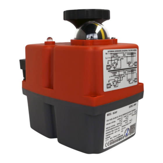
- Page 29 Kurzanleitung J4C S20-S300 Übersicht Bezeichnung 140-300 20-35-55-85 A Umschalter Handbetätigung B Handrad D Status LED E Schaltplan F Typenschild Modellübergreifend: Temperaturbereich Einschaltdauer Leistung Heizung Stromaufnahme bei max. Drehmoment Laufzeit ohne Arbeits- / Last Modell Losbrechmoment Gewicht Betrieb Statusleuchte (D) Betriebszustand...
- Page 30 Kurzanleitung J4C S20-S300 Nockensystem Einstellanleitung Der Antrieb ist ab Werk vorjustiert (siehe Typenschild). Abhängig von Anwendung, Armatur oder mangelndem Fluchten von Armaturenverbindungen oder Adaptern kann es notwendig sein, dass der Antrieb in seinem Verfahrweg angepasst werden muss. Sämtliche Arbeiten am geöffneten Antrieb dürfen nur unter Schutzkleinspannung oder im spannungslosen Zustand Elektrosicherheitsregeln können schwere Körperverletzungen oder Sachschäden auftreten.
Need help?
Do you have a question about the 20 and is the answer not in the manual?
Questions and answers