Table of Contents
Advertisement
Quick Links
Advertisement
Table of Contents

Related Manuals for Cincinnati Fan WAF


Summary of Contents for Cincinnati Fan WAF
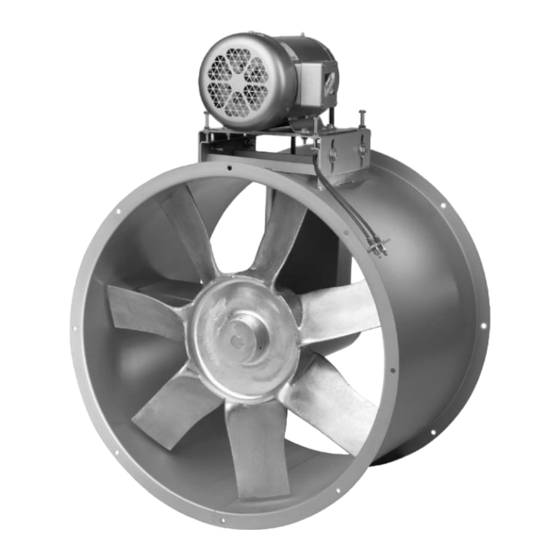
- Page 1 CINCINNATI FAN u s e r m a n u a l Arrangement 9 axial fan Models TAF - WAF - HTF - WAF/HTF I N STA L L AT I O N - O P E R AT I O N - M A I N T E N A N C E...
- Page 2 Altitude ft Airstream Temperature °F Do Not Exceed this RPM Fan RPM Maximum Safe Fan RPM Motor Data: (This section is completed only if the motor was supplied by Cincinnati Fan) Voltage Phase Frame Size Enclosure Efficiency If Motor is EXP, Class(es) and Group(s) are Manufacturer’s Model Number...
-
Page 3: Table Of Contents
contents General ................................4 - Unpacking and Handling ......................... 4 - Safety Instructions and Accessories ....................4 Installation ............................... 6 - Vibration ............................... 6 - Mounting Methods ............................ 7 - Safety Guards ............................7 - Dampers and Shutters ..........................7 - Set Screw and Taper-lock Bushing Torque .................. -
Page 4: General
general Receiving Unpacking Be careful not to damage or deform any parts of the fan when removing it from the packaging container. All the packaging material should be kept in the event the fan needs to be returned. Handling Handling the fan should be performed by trained personnel and be consistent with all safe handling practices. - Page 5 general Temperature Many fans, fan components and all motors operate at temperatures that Caution could burn someone if they come in contact with them. If this potential hazard could exist in your installation, steps must be taken by the user to protect anyone from coming in contact with this equipment.
-
Page 6: Installation
installation Installation Vibration Before any mounting method is selected, the user should be aware of the effects vibration will have on the fan, motor and other parts. Improper fan instal- lation can cause excessive vibration causing premature prop and/or bearing failure, that is not covered under warranty. -
Page 7: Mounting Methods
Safety Guards Cincinnati Fan offers guards, as options, to keep your fan in compliance with OSHA safety regulations. These include inlet or discharge guards and belt guards. It is the responsibility of the user to make sure this fan meets all local, state and OSHA safety regulations. -
Page 8: Fan Bearings
The bearing cover must be replaced before the power is turned back on. V-Belt Drive If Cincinnati Fan supplied the belts and sheaves (drives package), they were carefully selected for the specific operating conditions supplied to us by the customer. -
Page 9: V-Belt Installation
installation V-Belt Drive Installation Power to the motor must be turned off and locked out, Before inspecting, installing or servicing any components of the drives. Follow the following steps. If installing new belts, inspect and replace any worn or damaged sheaves, bearings or shafts while the power is turned off and locked out. - Page 10 installation Remove belt(s) from the motor sheave and then the fan sheave. Remove belt(s) from through the belt tube. If replacing belts and sheaves, go on to Step 7. If replacing belts only, go to Step 12. Loosen set screws or taper-lock bolts in the fan sheave and the motor sheave.
- Page 11 installation 16. Loosen the four locking bolts in the side of the motor base, and re-adjust the belt tension using the four tensioning bolts in the top of the base. 17. Tighten the four locking bolts in the side of the motor base. 18.
-
Page 12: Electrical
installation Electrical Disconnect Switches: All fan motors should have an independent disconnect switch located in close visual proximity to turn off the electrical service to the fan motor. Disconnects must be locked out in accordance with OSHA “lock out-tag out” procedures any time inspection or maintenance is being performed on the fan and/or motor assembly. - Page 13 installation Location: A standard Open Drip Proof or Totally Enclosed type motor is suitable in a clean, dry location below 104°F (40°C). If the location will be wet, dirty or reach temperatures above 104°F (40°C), a different type of motor may be necessary. Consult our local sales office for your area for proper motor selection assistance.
-
Page 14: Maximum Speed And Speed Controllers
If you have lost the data sheet, contact Cincinnati Fan or the sales office for your area. You must have the serial number from the fan name plate for us to determine the maximum safe fan speed. -
Page 15: Initial Unit Startup
operation Pre-Startup and Post-Startup Check (Check blocks as each step is completed. Retain for you records) Failure to complete and document all the following Pre-Startup checks, Note Post-Startup checks and Vibration checks, could void all warranties. Before mounting fan in duct work or on a machine: If mounting this fan into a duct system with no access door in the fan drum, it is strongly recommended that an access door be installed in the duct work section next to the fan. -
Page 16: Vibration
operation Pre-Startup Check completed by: Date Eight Hour Post-Startup Check completed by: Date Three-Day Post-Startup Check completed by: Date Apply power to the motor momentarily (i.e. bump start) to check for propeller fan rotation. If the fan is n n n n n n rotating in the wrong direction, reconnect the motor leads per the motor manufacturers wiring schematic. -
Page 17: Routine Inspection And Maintenance
If the operating conditions of the fan are to be changed (speed, pressure, temperature, etc.) consult Cincinnati Fan or our sales office in your territory to determine if the unit will operate safely at the new conditions. - Page 18 maintenance For HTF and HTF/WAF model fans, the maximum airstream temperature limit is 375°F (191°C). A chart similar to the chart below will also specify that only Dow Corning DC-44 high temperature (silicone based) grease should be used. Do not overgrease the fan bearings. Generally, 1-2 shots should be enough. Use a hand-operated grease gun at no more than 40 PSI.
-
Page 19: Propeller Balance
maintenance Propeller Balancing All propellers are balanced at the factory. It is not uncommon that additional “trim balancing” is required after the fan is assembled. Trim balancing of the fan assembly, in the field, is typically always necessary for all replacement propellers. -
Page 20: Fan Shaft Or Bearing Replacement
Fan Shaft and Bearing Replacement The fan shaft and bearings for Cincinnati Fan tube axial fans are carefully se- lected to match the maximum load and operating conditions. If the instructions in this manual and those provided by the bearing manufacturer are followed, you should not need to replace the bearings for many years. - Page 21 maintenance 12. Slide the belt(s) off of the motor sheave and then the fan sheave. 13. Remove the belt(s) through the top of the belt tube. 14. Loosen the set screws, or the bolts in the taper-lock bushing, of the fan sheave and remove the sheave from the fan shaft.
- Page 22 maintenance 28. Replace the set screws in the fan sheave or the bolts in the fan sheave, taper-lock bushing. 29. Re-install the fan sheave onto the fan shaft and check the fan sheave alignment with the motor sheave. Both sheaves must be aligned as shown in Figure 2.
-
Page 23: Dampers And Shutters
maintenance 34. WAF/HTF models only: Re-apply a small bead of silicone caulk on the back surface of the cover that you removed in Step 10. Slide the cover over the fan shaft and mount it on the front of the bearing cover with the four screws. -
Page 24: Safety Equipment And Accessories
Replacement Parts Under normal conditions, you should not need any spare or replacement parts for at least 24 months after shipment from Cincinnati Fan. That does not include any wear due to abrasion, corrosion, excessive temperatures, abuse, misuse, accident or any severe conditions the fan was not designed for. -
Page 25: Troubleshooting
maintenance Troubleshooting Potential problems and causes listed below are in no order of importance or priority. The causes are only a list of the most common items to check to correct a problem. If you find the cause of a problem, do not assume it is the only cause of that problem. -
Page 26: Long Term Storage
maintenance Propeller rubbing inside of housing Worn or corroded propeller Accumulation of foreign material on propeller Loose mounting bolts, set screws or taper-lock hub bolts Bent motor shaft or fan shaft Worn motor and/or fan bearings Excessive Noise Motor out of balance Motor and/or fan bearings need lubrication Vibration originating elsewhere in system System resonance or pulsation... - Page 27 maintenance • Storage Maintenance: A periodic inspection and maintenance log, by date and action taken, Note must be developed and maintained for each fan. See example below. Each item must be checked monthly. Storage/Maintenance Schedule Log Example Action Date Checked Reinspect units to insure any protective devices used are functioning properly.
-
Page 28: Warranty, Limits Of Liability, Responsibility And Returns
Limited Warranty Cincinnati Fan and Ventilator Company (Seller) warrants products of its own manufacture, against defects of material and workman-ship under normal use and service for a period of eighteen (18) months from date of shipment or twelve (12) months from date of installation, whichever occurs first. This warranty does not apply to any of Seller’s products or any part thereof which has been... - Page 29 Purchaser’s and/or User’s compliance with any Federal, State and local regulations. Returns Cincinnati Fan & Ventilator Company assumes no responsibility for any mate- rial returned to our plant without our permission. An RMA (Return Material Authorization) number must be obtained and clearly shown on the outside of the carton or crate and on a packing slip.
-
Page 30: Parts Drawing
Or, you can print a current version by going to our website at: cincinnatifan.com. Parts Drawing Cincinnati Fan manufactures many models and arrangements with special variations. For that reason, the maintenance manuals contained on our website do not include a parts drawing nor the completed blower or fan specifications on page 2. - Page 32 Axial Fan U S E R M A N UA L SPX ENGINEERED AIR MOVEMENT CF-15-IOM-24 ISSUED 5/2024 ©2024 SPX ENGINEERED AIR MOVEMENT ALL RIGHTS RESERVED 7697 SNIDER ROAD In the interest of technological progress, all products are subject to design T E C H N O L O G I E S MASON, OH 45040 USA and/or material change without notice.
Need help?
Do you have a question about the WAF and is the answer not in the manual?
Questions and answers