Table of Contents
Advertisement
Quick Links
Advertisement
Table of Contents

Related Manuals for Cincinnati Fan Arrangement 9 BAF


Summary of Contents for Cincinnati Fan Arrangement 9 BAF
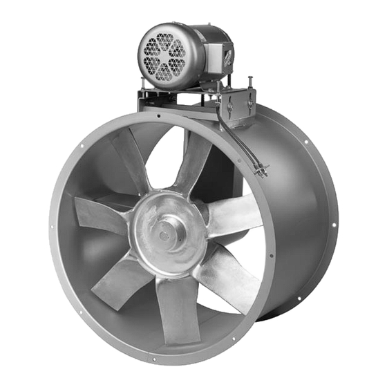
- Page 1 CINCINNATI FAN u s e r m a n u a l Arrangement 9 axial fan Model BAF I N STA L L AT I O N - O P E R AT I O N - M A I N T E N A N C E...
- Page 2 Altitude ft Airstream Temperature °F Do Not Exceed this RPM Fan RPM Maximum Safe Fan RPM Motor Data: (This section is completed only if the motor was supplied by Cincinnati Fan) Voltage Phase Frame Size Enclosure Efficient If Motor is EXP, Class(es) and Group(s) are Manufacturer’s Model Number...
-
Page 3: Table Of Contents
contents General ................................4 - Unpacking and Handling ......................... 4 - Safety Instructions and Accessories ....................4 Installation ............................... 6 - Vibration ............................... 6 - Mounting Methods ............................ 6 - Safety Guards ............................7 - Dampers and Shutters ..........................7 - Set Screw and Taper-lock Bushing Torque .................. -
Page 4: General
general Receiving Unpacking Be careful not to damage or deform any parts of the fan when removing it from the packaging container. All the packaging material should be kept in the event the fan needs to be returned. Handling Handling the fan should be performed by trained personnel and be consistent with all safe handling practices. - Page 5 general Never operate a fan with a non-ducted inlet and/or discharge. If the fan Caution inlet and/or discharge is non-ducted, it is the users responsibility to install an inlet and/or discharge guard. Temperature Many fans, fan components and all motors operate at temperatures that could burn someone if they come in contact with them.
-
Page 6: Installation
installation Installation Vibration Before any mounting method is selected, the user should be aware of the effects vibration will have on the fan, motor and other parts. Improper fan installation can cause excessive vibration causing premature propeller and/ or bearing failure, that is not covered under warranty. Vibration eliminator pads or springs should be properly installed to prevent any fan vibration from transmitting to the foundation or support structure. -
Page 7: Safety Guards
Safety Guards Cincinnati Fan offers guards, as options, to keep your fan in compliance with OSHA safety regulations. These include inlet or discharge guards and belt guards. It is the responsibility of the user to make sure this fan meets all local, state and OSHA safety regulations. -
Page 8: Fan Bearings
The maximum airstream temperature for this fan is 175°F (79°C). V-Belt Drive If Cincinnati Fan supplied the belts and sheaves (drives package), they were carefully selected for the specific operating conditions supplied to us by the customer. -
Page 9: V-Belt Installation
All Tube Axial fans shipped from Cincinnati Fan are supplied with belts and sheaves even if the motor is not supplied by Cincinnati Fan. If you are supply- ing the motor, you will also need to install the drives after the motor is installed onto the motor base. -
Page 10: Motor
installation Motor All wiring connections, inspection and maintenance of any motor must be Warning performed by a licensed electrician in accordance with the motor manu- facturers recommendations, all electrical codes and OSHA regulations. Failure to properly install, make wiring connections, inspect or perform any maintenance to a motor can result in motor failure, property damage, explosion, electrical shock and death. - Page 11 installation Motors with Thermal Overload Protection: If a motor is equipped with thermal overloads, the thermal overload must be wired per the wiring schematic to be operable. There are three types of thermal overloads: Automatic: These will automatically shut the motor down if the internal temperature exceeds the design limits.
-
Page 12: Maximum Speed And Speed Controllers
If you have lost the data sheet, contact Cincinnati Fan or the sales office for your area. You must have the serial number from the fan name plate for us to determine the maximum safe fan speed. -
Page 13: Initial Unit Startup
operation Pre-Startup and Post-Startup Check (Check blocks as each step is completed. Retain for you records) Failure to complete and document all the following Pre-Startup checks, Note Post-Startup checks and Vibration checks, could void all warranties. Pre-Startup Check completed by: Date Eight Hour Post-Startup Check completed by: Date... -
Page 14: Vibration
operation Pre-Startup Check completed by: Date Eight Hour Post-Startup Check completed by: Date Three-Day Post-Startup Check completed by: Date Apply power to the fan motor and let it come up to full speed. Turn off the power. Listen for any unusual n n n n n n noise or mechanical abnormality while the propeller is still spinning. -
Page 15: Routine Inspection And Maintenance
If the operating conditions of the fan are to be changed (speed, pressure, temperature, etc.) consult Cincinnati Fan or our sales office in your territory to determine if the unit will operate safely at the new conditions. -
Page 16: Propeller Balance
maintenance Propeller Balancing All propellers are balanced at the factory. It is not uncommon that additional “trim balancing” is required after the fan is assembled. Trim balancing of the fan assembly, in the field, is typically always necessary for all replacement propellers. -
Page 17: Replacing Belts Only
maintenance Belt Replacement Only — All Fan Sizes The propeller does not need to be removed from the system Note Before any maintenance or inspection should only be performed by quali- fied, trained maintenance personnel. Before starting any maintenance or inspection, make sure the power to the Warning fan motor is turned off and locked out in accordance with OSHA “lock-out/ tag-out”... - Page 18 maintenance 12. Now tighten the four locking bolts in the side of the motor base. Use extreme caution while performing the following steps 13 and 14. Warning 13. Unlock power to the motor and run the fan for 20 minutes. This will allow the belts to seat in the sheave grooves 14.
- Page 19 maintenance Straight edge Straight should touch Edge sheaves at these 4 points Figure 2 Too Tight Proper Tension Figure 3 Too Loose (slight bow) 32. After running the fan for 100 hours, turn off and lock out power to the motor.
-
Page 20: Replacing Shaft And Bearing Assembly, Belts And Sheaves
maintenance Belt, Sheave and Bearing Assembly Replacement You must remove the fan from the system to complete the following steps. Note If you need to replace both the belts and the sheaves, you should also replace the fan shaft and bearing assembly at the same time. This will save you additional down time later. - Page 21 maintenance c. All size 24" fans, with 1" fan shafts have a belt tube with an access hole in the center d. All size 30" to 42" fans have a belt tube with an access hole in the center. - On the fan sizes without the access hole, remove the belts from the end of the belt tube.
- Page 22 maintenance 22. Carefully re-install the propeller onto the fan shaft. Do Not pound the propeller hub with a hammer. 23. Locate the propeller hub at the same position on the shaft that was measured in Step 12. 24. Line up the keyway in the propeller hub with the keyway in the fan shaft and insert a new key.
- Page 23 maintenance 39. After 20 minutes, carefully look down the belt tube to observe if the belts are running as indicated in Figure 3. 40. Turn off and lock out power to the motor. 41a. If the belts are running as per Figure 3, re-install the belt guard or weather cover if present, then proceed to Step 42.
-
Page 24: Dampers And Shutters
Replacement Parts Under normal conditions, you should not need any spare or replacement parts for at least 24 months after shipment from Cincinnati Fan. That does not include any wear due to abrasion, corrosion, excessive temperatures, abuse, misuse, accident or any severe conditions the fan was not designed for. -
Page 25: Troubleshooting
maintenance • If this fan is vital for the safety of any people and/or animals, we strongly recommend that you keep a complete fan/motor assembly, as originally ordered, at your location. To order parts or complete units, contact us for the name of our sales office in your area or locate them on our website at cincinnatifan.com. -
Page 26: Long Term Storage
maintenance Actual system static pressure (SP) is lower than expected Voltage supplied to motor is too high or too low Motor speed (RPM) too high or defective motor Motor Overheating Air density higher than expected Motor wired incorrectly and/or loose wiring connections Note —... - Page 27 information rective action taken if discrepancies are found, to insure adequate protection of the equipment during storage. - Sheave center distance should be reduced to reduce tension on the belts. • Storage Maintenance: A periodic inspection and maintenance log, by date and action taken, Note must be developed and maintained for each fan.
-
Page 28: Warranty, Limits Of Liability, Responsibility And Returns
Limited Warranty Cincinnati Fan and Ventilator Company (Seller) warrants products of its own manufacture, against defects of material and workman-ship under normal use and service for a period of eighteen (18) months from date of shipment or twelve (12) months from date of installation, whichever occurs first. This warranty does not apply to any of Seller’s products or any part thereof which has been... - Page 29 Purchaser’s and/or User’s compliance with any Federal, State and local regulations. Returns Cincinnati Fan & Ventilator Company assumes no responsibility for any mate- rial returned to our plant without our permission. An RMA (Return Material Authorization) number must be obtained and clearly shown on the outside of the carton or crate and on a packing slip.
-
Page 30: Parts Drawing
Or, you can print a current version by going to our website at: cincinnatifan.com. Parts Drawing Cincinnati Fan manufactures many models and arrangements with special variations. For that reason, the maintenance manuals contained on our website do not include a parts drawing nor the completed blower or fan specifications on page 2. - Page 32 Axial Fan U S E R M A N UA L SPX ENGINEERED AIR MOVEMENT CF-12-IOM-24 ISSUED 5/2024 ©2024 SPX ENGINEERED AIR MOVEMENT ALL RIGHTS RESERVED 7697 SNIDER ROAD In the interest of technological progress, all products are subject to design T E C H N O L O G I E S MASON, OH 45040 USA and/or material change without notice.
Need help?
Do you have a question about the Arrangement 9 BAF and is the answer not in the manual?
Questions and answers