Table of Contents
Advertisement
Quick Links
CINCINNATI FAN
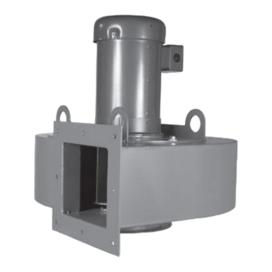
Arrangement 4HM centrifugal blower
Models HP I - HP II - RBE - HDBC - HDBI - HDAF
I N STA L L AT I O N - O P E R AT I O N - M A I N T E N A N C E
CF-07-IOM-24
ISSUED 06/2024
Blower Serial Number
READ AND UNDERSTAND THIS MANUAL PRIOR TO OPERATING OR SERVICING THIS PRODUCT
RBE Centrifugal Blower
u s e r m a n u a l
Advertisement
Table of Contents

Related Manuals for Cincinnati Fan Arrangement 4HM


Summary of Contents for Cincinnati Fan Arrangement 4HM
- Page 1 CINCINNATI FAN u s e r m a n u a l Arrangement 4HM centrifugal blower Models HP I - HP II - RBE - HDBC - HDBI - HDAF I N STA L L AT I O N - O P E R AT I O N - M A I N T E N A N C E...
- Page 2 Altitude ft Airstream Temperature °F Do Not Exceed this RPM Fan RPM Maximum Safe Fan RPM Motor Data: (This section is completed only if the motor was supplied by Cincinnati Fan) Voltage Phase Frame Size Enclosure Efficiency If Motor is EXP, Class(es) and Group(s) are Manufacturer’s Model Number...
-
Page 3: Table Of Contents
contents This manual contains vital information for the proper installation and Note operation of your blower fan. Carefully read the manual before installa- tion or operation of the blower fan and follow all instructions. Save this manual for future reference. General ................................ -
Page 4: General
general Receiving Unpacking Be careful not to damage or deform any parts of the blower when removing it from the packaging container. All the packaging material should be kept in the event the blower needs to be returned. Handling Handling of the blower should be performed by trained personnel and be consistent with all safe handling practices. - Page 5 general Never operate a blower with a non-ducted inlet and/or discharge. If the Caution blower inlet and/or discharge is non-ducted, it is the users responsibility to install an inlet and/or discharge guard. Temperature Many blowers, blower components and all motors operate at temperatures that could burn someone if they come in contact with them.
-
Page 6: Installation
• With motor shaft vertical (perpendicular to floor): This is the best way to mount an Arrangement 4HM blower as long as the mounting plate the flange will be bolted to is rigid enough to support the weight of the blower/motor assembly. -
Page 7: Duct Work Connections
Safety Guards Cincinnati Fan offers guards, as optional, to keep your blower in compliance with OSHA safety regulations. These include inlet or discharge guards. Any blowers built with high temperature construction, a “heat slinger guard” is standard. -
Page 8: Set Screw And Taper-Lock Bushing Torque Values
installation Set Screw and Taper-Lock Bushing Torque Values All blower wheel set screws are tightened to the proper torque prior to ship- ment. Some wheels may have taper-lock hubs and split, taper-lock bushings to secure the wheel to the blower shaft. Check all set screw or taper-lock bushing torques. -
Page 9: Motor
installation All disconnects should be sized in accordance with the latest NEC codes (National Electric Codes) and any local codes and should be installed only by a licensed electrician. “Slow blow” or “time delay” fuses or breakers should be used since the initial start-up time for the blower motor, although rare, can be up to 10 seconds. - Page 10 installation 5. Wiring Connections: All wiring connections should be made for the proper voltage and phase as shown on the motor nameplate. Connections should follow the motor manufacturers recommendations as shown on the wiring schematic. This wiring diagram will be located on the outside of the mo- tor, inside of the motor conduit box or on the motor nameplate.
-
Page 11: Maximum Blower Speed
Fan or the sales office for your area. You must have the serial number from the blower name plate for us to determine the maximum safe blower speed. Cincinnati Fan will only extend the motor manufacturers warranty, when used with a speed controlling device, if the motor has the words Inverter Duty marked on the motor name plate. -
Page 12: Initial Unit Startup
operation Initial Unit Startup Pre-Startup and Post-Startup Check (Check blocks as each step is completed. Retain for you records) Failure to complete and document all the following Pre-Startup checks, Note Post-Startup checks and Vibration checks, could void all warranties. Pre-Startup Check completed by: Date Eight Hour Post-Startup Check completed by: Date... -
Page 13: Vibration
operation Pre-Startup Check completed by: Date Eight Hour Post-Startup Check completed by: Date Three-Day Post-Startup Check completed by: Date Apply power to the blower motor momentarily (bump start) to check for proper blower wheel rotation. n n n n n n If the blower is rotating in the wrong direction, reconnect the motor leads per the motor manufacturer’s wiring schematic. - Page 14 operation The blower Should Not be operated if the vibration velocity of the blower Caution exceeds 0.40 inches per second, filter out, if the blower is rigidly mounted. If the blower is mounted on isolators or on an isolator base, it Should Not be operated if the vibration velocity of the blower exceeds 0.65 inches per second, filter out.
- Page 15 operation Alarm, rigid mount (.40) Normal, rigid mount (.25) Figure 3 Vibration Severity Graph...
-
Page 16: Routine Inspection And Maintenance
If the operating conditions of the blower are to be changed (speed, pressure, temperature, etc.) consult Cincinnati Fan or our sales office in your territory to determine if the unit will operate safely at the new conditions. -
Page 17: Vibration
Make sure you reinstall the wheel so the proper wheel-to-inlet clearance is maintained. Failure to do this will affect the blower’s airflow (CFM), and/or static pressure (SP) capabilities and ef- ficiency. Consult Cincinnati Fan or our local sales office for your area for assistance if necessary. Vibration As mentioned previously in this manual, excessive vibration can cause prema- ture motor failure that could lead to catastrophic failure of the blower. -
Page 18: Dampers And Valves
Replacement Parts Under normal conditions, you should not need any spare or replacement parts for at least 24 months after shipment from Cincinnati Fan. That does not include Note any wear due to abrasion, corrosion, excessive temperatures, abuse, misuse, accident or any severe conditions the fan was not designed for. -
Page 19: Troubleshooting
maintenance Troubleshooting Potential problems and causes listed below are in no order of importance or priority. The causes are only a list of the most common items to check to correct a problem. If you find the cause of a problem, do not assume it is the only cause of that problem. -
Page 20: Long Term Storage
maintenance Wheel rubbing Worn or corroded blower wheel Accumulation of foreign material on blower wheel Loose mounting bolts, set screws or taper-lock hub bolts, bearings or sheaves Bent motor shaft Worn motor bearings Excessive Noise Motor out of balance Motor bearings need lubrication Vibration originating elsewhere in system System resonance or pulsation Inadequate or faulty design of blower support structure... - Page 21 maintenance Storage/Maintenance Schedule Log Example Action Date Checked Reinspect units to insure any protective devices used are functioning properly. Check for scratches in the finish which will allow corrosion or rust to form Rotate blower wheel a minimum of 10 full revolutions to keep the moor bearing grease from separating and drying.
-
Page 22: Warranty, Limits Of Liability, Responsibility And Returns
Limited Warranty Cincinnati Fan and Ventilator Company (Seller) warrants products of its own manufacture, against defects of material and workman-ship under normal use and service for a period of eighteen (18) months from date of shipment or twelve (12) months from date of installation, whichever occurs first. This warranty does not apply to any of Seller’s products or any part thereof which has been... - Page 23 information Limitation of Liability Notice of any claim, including a claim for defect in material or workmanship, must be given to Seller in writing within 30 days after receipt of the equipment or other products. Seller reserves the right to inspect any alleged defect at Purchaser’s facility before any claim can be allowed and before adjustment, credit, allowance replacement or return will be authorized.
- Page 24 Purchaser’s and/or User’s compliance with any Federal, State and local regulations. Returns Cincinnati Fan & Ventilator Company assumes no responsibility for any mate- rial returned to our plant without our permission. An RMA (Return Material Authorization) number must be obtained and clearly shown on the outside of the carton or crate and on a packing slip.
-
Page 25: Parts Drawing
Parts Drawing Cincinnati Fan manufactures many models and arrangements with special variations. For that reason, the maintenance manuals contained on our website do not include a parts drawing nor the completed blower or fan specifica- tions on page 2. For the parts drawing of all the standard components and specifications for the specific blower or fan that you have, please contact our local Cincinnati Fan sales office for your area. - Page 28 Centrifugal Blower U S E R M A N UA L SPX ENGINEERED AIR MOVEMENT CF-07-IOM-24 ISSUED 06/2024 ©2024 SPX ENGINEERED AIR MOVEMENT ALL RIGHTS RESERVED 7697 SNIDER ROAD In the interest of technological progress, all products are subject to design T E C H N O L O G I E S MASON, OH 45040 USA and/or material change without notice.
Need help?
Do you have a question about the Arrangement 4HM and is the answer not in the manual?
Questions and answers