
Related Manuals for Vela Blues 210


Summary of Contents for Vela Blues 210
- Page 1 M O U N T I N G I N S T R U C T I O N S Lashing & docking kit VELA Blues 100, 210, 300 & 1100 REGARDING: Manual no. 105903...
-
Page 2: Table Of Contents
2.0.2. Mounting the tubular leg on C-rails 2.0.3. Mounting the rear securing fitting, folding armrest 2.0.3.1. Mounting the rear securing fitting, folding armrest (VELA Blues 210) 2.1. LEG SUPPORT 2.0.4. Mounting the rear lashing fitting, fixed armrest 2.1.1. Resizing of hole in fitting for electric leg support 2.1.2. -
Page 3: Introduction
1.0. INTRODUCTION DEAR CUSTOMER We would like to thank you for purchasing a VELA lashing & docking kit. This user manual contain useful information about positioning, operating and mainten- ance of the VELA lashing & docking kit. Important Please read this user manual thoroughly and keep it for later use. -
Page 4: Safety
Item number for docking station mounting kit: 926425. For the VELA Blues 100, 210, 300 & 1100 to be used as a passenger seat See section 2.0 re. mounting the of a motor vehicle, the chair must... -
Page 5: Warranty
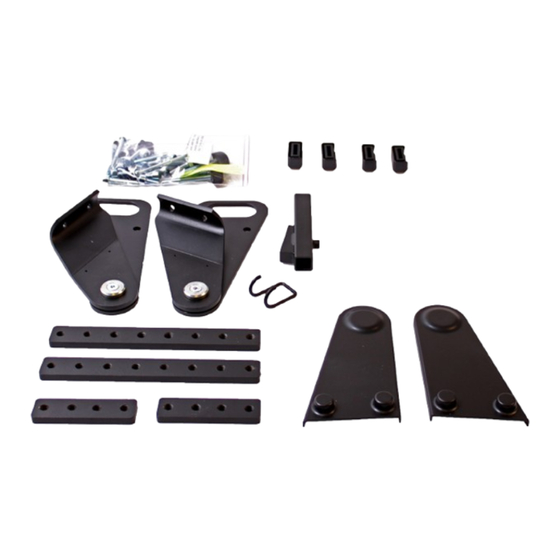
:: Use of non-original spare parts and accessories :: Adjustments carried out by unauthorised service technicians 1.3. UNPACKING THE KIT VELA lashing & docking kit is sup- plied in cardboard packaging, de- veloped with consideration for the environment. If there are any parts missing or transport damage to the chair, plea- se contact your dealer immediately. -
Page 6: Mounting The Lashing Kit
M8x20 skruer screws (30 NM). 2.0.3.1. MOUNTING THE REAR SECURING FITTING, FOLDING ARMREST (VELA BLUES 210) First, fit the block with 8 threaded holes into the C-rail and firmly tighten the 2 x pinol screws (11 NM), one of them into the first threaded hole and one in the second. -
Page 7: Leg Support
Mounting the edge covering Lift the top of the armrest and push the edge covering down over the part attached to the chair and then repla- ce the upper part. This is done on both sides. The purpo- se of the edge covering is to prevent sharp edges cutting through the seatbelt in the event of sudden braking or a collision. -
Page 8: Replacement Of Screws And Bolts
2.1.3. SCREWS IN LEG SUPPORT An M5 thread has to be cut into the base of the leg support. To prevent the leg support falling off, a M5x65 screw is fitted into the leg support from below. The screw must not be screwed so far in as to prevent the leg support being lifted and turned to the side. -
Page 9: Position Of Labels
2.3. POSITION OF LABELS Position of labels on fittings Position of label on VELA Blues 100 Position of label on VELA Blues 210 Position of label on VELA Blues 300 Position of label on VELA Blues 1100... -
Page 10: Advice And Guidance
3.0. ADVICE AND GUIDANCE 3.0.1. LASHING DOWN AN ELECTRIC WHEEL CHAIR When lashing down a wheelchair into a vehicle to be used as a passenger seat, certain precautions apply to ensure that the wheelchair is lashed down as safely as possible. :: The chair must be set at its lowest position. -
Page 11: Positioning The 3-Point Seat Belt On The User
3.1. POSITIONING THE 3-POINT SEAT BELT ON THE USER 3.1.1. WRONG POSITIONING OF SEATBELT Beware: The 3-point seat belt must not be tightened across sharp edges. The drawing shows the incorrect positioning of a 3-point seatbelt. 3.1.2. CORRECT POSITIONING OF SEATBELT Beware: Seatbelts must not be held away from the body by parts of the wheelchair, such as arm rests, wheels, etc. -
Page 12: Mounting The Base Plate And Locking Plate
Base plate is mounted on the chassis using 4x M8x40 button head scews fastened with M8 lock nuts. The large apertures in the base plate must face backwards. vela.eu VELA :: Gøteborgvej 8-12 :: 9200 Aalborg SV :: Denmark :: +45 96 34 76 00 :: mail@vela.dk...
Need help?
Do you have a question about the Blues 210 and is the answer not in the manual?
Questions and answers