Table of Contents
Advertisement
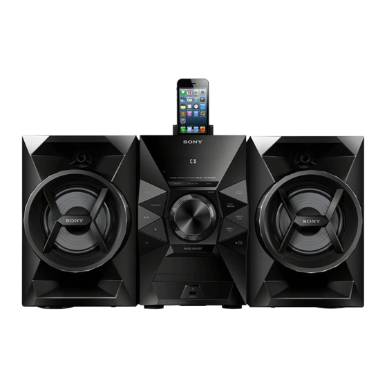
MHC-EC619iP/EC719iP/EC919iP
SERVICE MANUAL
Ver. 1.0 2013.08
• MHC-EC619iP/EC719iP/EC919iP are composed of following models.
MHC-EC619iP
Compact Disc Receiver
Front Speaker
Subwoofer
Note 1: The speaker (SS-ECL5) supplied with MHC-EC619iP has a different service policy
from the speaker (SS-ECL5) supplied with other models. For SS-ECL5 supplied with
models other than MHC-EC619iP, refer to the separate SS-ECL5 service manual.
Be sure to check the system model name before beginning service.
Note 2: The speaker (SS-EC719iP) supplied with MHC-EC719iP (US and Australian models)
and the speakers (SS-EC719iP/WG919iP) supplied with MHC-EC919iP (Australian
model) have different service policies from speakers (SS-EC719iP/WG919iP) sup-
plied with different models (or intended for different regions).
For SS-EC719iP or SS-WG919iP supplied with models other than MHC-EC719iP (US
and Australian models) and MHC-EC919iP (Australian model), refer to the separate
SS-EC719iP/WG919iP service manual.
Be sure to check the system model name before beginning service.
PARTS LIST
Ref. No.
Part No.
Description
4-467-785-11
MANUAL, INSTRUCTION (ENGLISH)
4-467-785-21
MANUAL, INSTRUCTION (FRENCH)
4-467-785-31
MANUAL, INSTRUCTION (SPANISH)
4-467-785-41
MANUAL, INSTRUCTION (GERMAN)
4-467-785-51
MANUAL, INSTRUCTION (DUTCH)
4-467-785-61
MANUAL, INSTRUCTION (ITALIAN)
4-467-785-71
MANUAL, INSTRUCTION (POLISH)
4-467-786-11
MANUAL, INSTRUCTION (ENGLISH)
4-467-786-31
MANUAL, INSTRUCTION (SPANISH)
• Abbreviation
AUS
: Australian model
CND : Canadian model
E2
: 120V AC area in E model
9-893-792-01
Sony Corporation
2013H33-1
©
2013.08
Published by Sony Techno Create Corporation
HCD-EC619iP/EC719iP/EC919iP/SS-EC719iP/ECL5/WG919iP
MHC-EC719iP
HCD-EC619iP
HCD-EC719iP
SS-ECL5
SS-EC719iP
–
–
• The service policy of these models are Product Exchange.
The following parts are available for service parts of these models.
Remark
(EC619iP: US, CND, UK, E2, AUS)
(EC619iP: CND, AEP, E2)
(EC619iP: US, AEP, E2)
(EC619iP: AEP)
(EC619iP: AEP)
(EC619iP: AEP)
(EC619iP: AEP)
(EC719iP/EC919iP)
(EC719iP: US)
MHC-EC919iP
HCD-EC919iP
SS-EC719iP
Australian Model
SS-WG919iP
MHC-EC619iP/EC719iP/EC919iP
Ref. No.
Part No.
Description
1
A-1970-520-A
REMOTE COMMANDER (RM-AMU185)
1
A-1970-521-A
REMOTE COMMANDER (RM-AMU186)
2
4-486-327-01
SPEAKER PAD (PORON T2) (Speaker pads)
2
4-486-328-01
SPEAKER PAD (SILICON T4) (Speaker pads)
3
9-885-189-78
AM ANTENNA (AM loop antenna)
4
9-885-189-79
FM ANTENNA (FM lead antenna)
1
1
2
RM-AMU185
RM-AMU186
Speaker pads
4
FM lead antenna
HOME AUDIO SYSTEM
US Model
MHC-EC619iP/EC719iP
Canadian Model
AEP Model
UK Model
E Model
MHC-EC619iP
Remark
(Remote control) (EC619iP)
(Remote control) (EC719iP/EC919iP)
(4 pieces, 1 sheet) (EC619iP)
(4 pieces, 1 sheet) (EC719iP/EC919iP)
(EC719iP/EC919iP)
3
AM loop antenna
(MHC-EC719iP/EC919iP)
Advertisement
Table of Contents

Related Manuals for Sony SS-ECL5


Summarization of Contents
SPECIFICATIONS
AUDIO POWER SPECIFICATIONS
Details power output and total harmonic distortion for different models.
SYSTEM COMPONENTS
Information on amplifier, input, output, CD, tuner, dock, and USB sections.
GENERAL SPECIFICATIONS
Provides power requirements, consumption, dimensions, and mass for the unit.
SAFETY CHECK-OUT
LEAKAGE TEST
Procedure to check for AC leakage current from exposed metal parts to earth ground.
SERVICING NOTES
TEST DISCS
Lists test discs required for confirming unit operation and checks.
RELEASING THE DISC TRAY LOCK
Procedure to release the disc tray lock function for antitheft.
CAPACITOR ELECTRICAL DISCHARGE PROCESSING
Procedure for necessary electrical discharge before checking boards to prevent shock.
DISASSEMBLY
DISASSEMBLY FLOW
Step-by-step flow chart for disassembling the unit.
SIDE COVER AND TOP COVER BLOCK REMOVAL
Detailed steps for removing the side cover and top cover assembly.
POWER CORD AND REAR PANEL BLOCK REMOVAL
Procedure for disconnecting and removing the power cord and rear panel block.
CD DOOR REMOVAL
Steps to remove the CD door assembly from the unit.
FRONT PANEL BLOCK REMOVAL
Procedure for removing the front panel block, including wire connections.
MAIN BOARD BLOCK DISASSEMBLY
Steps for removing the main board block, including flexible flat cable disconnection.
MAIN BOARD REMOVAL
Procedure for removing the main board, including heatsink and connectors.
POWER BOARD REMOVAL
Steps for removing the power board, including shield cover and wires.
FRONT BOARD REMOVAL
Procedure for removing the front board, including the volume knob and ground plate.
USB BOARD REMOVAL
Steps for removing the USB board and associated wiring.
LOADER WITH FFC REMOVAL
Procedure for removing the loader assembly with FFC, noting soldering requirements.
TEST MODES
SOFTWARE VERSION CHECK
Procedure to confirm the current software version of the unit.
FACTORY RESET PROCEDURE
Steps to clear memory and reset the unit to initial conditions.
TRAY LOCK AND RELEASE
Instructions for locking and unlocking the disc tray, typically for security.
CHILD LOCK FUNCTION
Procedure to lock the unit's controls, preventing accidental operation.
VFD TEST MODE
Procedure to test the functionality of the fluorescent indicator tube.
ELECTRICAL CHECKS
CD SECTION ELECTRICAL CHECK
Notes on CD block adjustments and necessary test discs/equipment.
RF SIGNAL CHECK PROCEDURE
Detailed steps and waveform confirmation for checking the RF signal.
CIRCUIT DIAGRAMS
BLOCK DIAGRAM OVERVIEW
High-level block diagram showing major functional units and their connections.
MAIN BOARD SCHEMATIC DIAGRAMS
Detailed schematic diagrams for the main board, broken into multiple parts.
EXPLODED VIEWS
COVER SECTION ASSEMBLY
Exploded view of the unit's covers and related assembly parts.
SPEAKER SPECIFICATIONS
FRONT SPEAKER SPECIFICATIONS
Technical details for the SS-EC719iP front speaker system.
SUBWOOFER SPECIFICATIONS
Technical details for the SS-WG919iP subwoofer system.
Need help?
Do you have a question about the SS-ECL5 and is the answer not in the manual?
Questions and answers