Sony ZS-PS30CP Service Manual
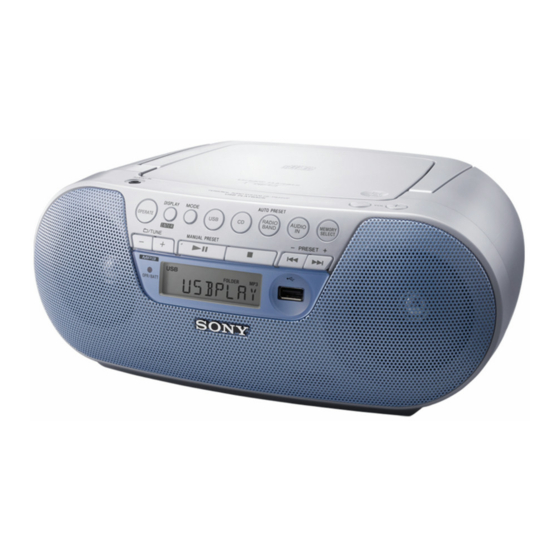
Personal audio system
Hide thumbs
Also See for ZS-PS30CP:
- Operating instructions (2 pages) ,
- Operating instructions manual (2 pages)
Table of Contents
Advertisement
SERVICE MANUAL
Ver. 1.1 2012.09
CD player section
System
Compact disc digital audio system
Laser diode properties
Emission duration: Continuous
Laser output: Less than 44.6 μW
(This output is the value measured at a distance of
about 200 mm from the objective lens surface on the
optical pick-up block with 7 mm aperture.)
Number of channels
2
Frequency response
20 Hz - 20,000 Hz +1/–2 dB
Wow and flutter
Below measurable limit
Radio section
Frequency range
Chilean, Peruvian, Asian and Argentina models
FM: 87.5 MHz - 108 MHz (50 kHz/100 kHz step)
AM: 531 kHz - 1,602 kHz (9 kHz step)
530 kHz - 1,610 kHz (10 kHz step)
Panamanian model
FM: 87.5 MHz - 108 MHz
AM: 530 kHz - 1,710 kHz
Taiwan model
FM: 87.5 MHz - 108 MHz
AM: 531 kHz - 1,602 kHz
Antennas
FM: Telescopic antenna
AM: Built-in ferrite bar antenna
9-893-461-02
Sony Corporation
2012I33-1
©
2012.09
Published by Sony Techno Create Corporation
ZS-PS30CP
Model Name Using Similar Optical Pick-up Block
Optical Pick-up Block Name
SPECIFICATIONS
USB section
Supported bit rate
MP3 (MPEG 1 Audio Layer-3):
32 kbps - 320 kbps, VBR
Sampling frequencies
MP3 (MPEG 1 Audio Layer-3):
32/44.1/48 kHz
(USB) port
USB-A (Full Speed)
General
Speaker
Full range: 8 cm dia., 8 Ω, cone type (2)
Outputs
Headphones jack (stereo minijack):
For 16 Ω - 32 Ω impedance headphones
Input
AUDIO IN jack (stereo minijack)
(USB) port: Type A, maximum current 500 mA
Power output
1.0 W + 1.0 W (at 8 Ω, 10% harmonic distortion)
Power requirements
For CD radio:
Chilean and Peruvian models: 230 V AC, 50 Hz
Panamanian and Taiwan models: 120 V AC, 60 Hz
Asian model: 230 V AC - 240 V AC, 50 Hz
Argentina model: 220 V - 230 V AC, 50 Hz
9 V DC, 6 R14 (size C) batteries (Except Argentina model)
Power consumption
AC 11 W
Battery life* (Except Argentina model)
For CD radio:
FM reception
R14P: approx. 7 h
Sony alkaline LR14: approx. 30 h
CD playback
R14P: approx. 1.5 h
Sony alkaline LR14: approx. 13 h
Dimensions
Approx. 299 mm × 126 mm × 210 mm (w/h/d)
(incl. projecting parts)
Mass
Approx. 2.4 kg (incl. batteries) (Except Argentina model)
Approx. 2 kg (Argentina model)
Supplied accessories
AC power cord (1)
* Battery life is subject to changes in surrounding temperature, usage
conditions, manufacture and battery type.
Design and specifications are subject to change without notice.
PERSONAL AUDIO SYSTEM
E Model
CFD-S07CP
DA11MMVGP
Advertisement
Table of Contents

Related Manuals for Sony ZS-PS30CP


Summary of Contents for Sony ZS-PS30CP
- Page 1 (This output is the value measured at a distance of 32/44.1/48 kHz about 200 mm from the objective lens surface on the (USB) port Sony alkaline LR14: approx. 30 h optical pick-up block with 7 mm aperture.) USB-A (Full Speed) CD playback...
-
Page 2: Table Of Contents
COMPONENTS IDENTIFIED BY MARK 0 OR DOTTED LINE WITH MARK 0 ON THE SCHEMATIC DIAGRAMS AND IN THE PARTS LIST ARE CRITICAL TO SAFE OPERATION. REPLACE THESE COMPONENTS WITH SONY PARTS WHOSE PART NUMBERS APPEAR AS SHOWN IN THIS MANUAL OR IN SUPPLEMENTS PUBLISHED BY SONY. - Page 3 ZS-PS30CP SECTION 1 SERVICING NOTES NOTES ON HANDLING THE OPTICAL PICK-UP CHUCK PLATE JIG ON REPAIRING BLOCK OR BASE UNIT On repairing CD section, playing a disc without the CD lid, use The laser diode in the optical pick-up block may suffer electro- CHUCK PLATE JIG.
- Page 4 ZS-PS30CP Ver. 1.1 MODEL IDENTIFICATION Distinguish the destination by referring to the model number label. MODEL NUMBER LABEL Chilean and Peruvian models 4-412-184-0s Panamanian model 4-412-186-0s Asian model – Bottom rear side view – 4-412-183-0s Taiwan model 4-412-188-0s Argentina model...
-
Page 5: Disassembly
ZS-PS30CP Ver. 1.1 SECTION 2 DISASSEMBLY • This set can be disassembled in the order shown below. 2-1. DISASSEMBLY FLOW (Argentina) 2-2. BATTERY CASE LID BLOCK (Argentina model) (Page 5) 2-3. CABINET (REAR) ASSY, FUSE (F901, F902) (Page 6) 2-4. VOL BOARD 2-16. -
Page 6: Cabinet (Rear) Assy, Fuse (F901, F902)
ZS-PS30CP Ver. 1.1 2-3. CABINET (REAR) ASSY, FUSE (F901, F902) Note 2: When you install the connector, please install them correctly. There is a possibility that this machine damages when not correctly installing it. 2 two tapping screws Insert is straight (BV B2.6) -
Page 7: Vol Board
ZS-PS30CP 2-4. VOL BOARD 4 two tapping screws (BV B2.6) 3 connector (CN305) 5 VOL board 2 connector 1 connector (CN306) (CN302) i e setti VOL board – Bottom side view – Note: When you install the connector, please install them correctly. -
Page 8: Cabinet (Front) Assy
ZS-PS30CP 2-5. CABINET (FRONT) ASSY 6 cabinet (front) assy 5 two claws tape – – 4 two tapping screws (BV B2.6) Note: When you install the connector, please install them correctly. There is a possibility that this machine damages when not correctly installing it. -
Page 9: Main Board Block
ZS-PS30CP 2-6. MAIN BOARD BLOCK Note 1: Before disconnecting the fl exible fl at cable (16 core) of optical pick-up block, solder the short-land. 1 tapping screw (PWH B2.6) 4 tapping screw (BV B2.6) 2 Remove ferrite core from rib. -
Page 10: Main Board
ZS-PS30CP 2-7. MAIN BOARD 2 flexible flat cable (16 core) (FFC801) ferrite core (FC1) (CN810) to POWER board from MAIN board Be based on tape a black line. Roll the wire three times. 1 ferrite core (FC1) 3 two cabinet upper cushions 10 X 7 X0.3... -
Page 11: Cd Block Assy
Note: Three claws might be fixed by bond. When installing the CD cover, please fix three claws using the following bond. Part No. Description 7-432-912-48 SONY BOND SC608LV (180 ml) 3 claw 3 claw 1 vibration proof rubber 3 claw (red) -
Page 12: Cd Spring
ZS-PS30CP 2-10. CD SPRING CD lid 5 CD spring 4 Insert the CD spring to the ditch of CD lid. CD spring CD lid ditch 1 Open the CD lid. 2 Remove the spring (CD) from the ditch of CD lid. -
Page 13: Speaker (7.7 Cm) (L-Ch) (Sp101)
ZS-PS30CP 2-12. SPEAKER (7.7 cm) (L-CH) (SP101) 2 Remove the speaker (7.7 cm) (L-CH) (SP101) in the direction of an arrow. 4 speaker (7.7 cm) (L-CH) (SP101) 1 four tapping screws (BV B2.6) – Cabinet (front) block rear right side view –... -
Page 14: Usb Jack Board
ZS-PS30CP 2-14. USB JACK BOARD USB JACK board 4 Remove the USB JACK board block in the direction of an arrow. 8 USB JACK board 3 tapping screw (BV B2.6) 7 shield plate (USB) 3 tapping screw 5 ferrite core (BV B2.6) -
Page 15: Speaker (7.7 Cm) (R-Ch) (Sp201)
ZS-PS30CP 2-15. SPEAKER (7.7 cm) (R-CH) (SP201) 2 Remove the speaker (7.7 cm) (R-CH) (SP201) in the direction of an arrow. 4 speaker (7.7 cm) (R-CH) (SP201) 1 four tapping screws (BV B2.6) – Cabinet (front) block rear left side view –... -
Page 16: Power Board
ZS-PS30CP 2-17. POWER BOARD 5 holder (inlet) 2 two tapping screws (BV B2.6) 2 two tapping screws (BV B2.6) 7 power transformer (T901) 2 tapping screw (BV B2.6) 8 POWER board 1 connector 3 Remove the POWER board block (CN903) in the direction of an arrow. -
Page 17: Test Mode
ZS-PS30CP SECTION 3 TEST MODE EEPROM CLR 10. Connect the oscilloscope to TP805 (TEI) and TP814 (GND) on the MAIN board. It can clear the EEPROM. oscilloscope Procedure: MAIN board 1. While pressing two buttons of [DISPLAY] and [ ] simulta- >... -
Page 18: Electrical Checks
ZS-PS30CP Ver. 1.1 SECTION 4 ELECTRICAL CHECKS 0 dB = 1 V TUNER SECTION CD SECTION Note: [AM] 1. CD block is basically constructed to operate without adjustment. Setting: 2. Use YEDS-18 disc (Part No. 3-702-101-01) unless otherwise indicat- Function: RADIO Band: AM 3. -
Page 19: Diagrams
ZS-PS30CP SECTION 5 DIAGRAMS 5-1. BLOCK DIAGRAM - MAIN Section - OPTICAL PICK-UP BLOCK INPUT SELECTOR, ELECTRICAL VOLUME (DA11MMVGP) IC303 83 FNI1 (A) 78 AGCI 1 IN LCD J302 R-CH 85 FPI1 (B) R-CH POWER AMP ICOUT L 13 VOLIN L... -
Page 20: Block Diagram - Panel/Power Supply Section
ZS-PS30CP Ver. 1.1 5-2. BLOCK DIAGRAM - PANEL/POWER SUPPLY Section - LIQUID CRYSTAL CD DSP, DISPLAY DRIVER SYSTEM CONTROLLER IC806 IC801 (2/2) SEG1 – DATA 61 DATA LCD401 SEG29 USB 3.3V CHK LIQUID 59 WR +3.3V CRYSTAL 60 CS USB +3.3V REGULATOR COM0 –... - Page 21 ZS-PS30CP Ver. 1.1 THIS NOTE IS COMMON FOR PRINTED WIRING BOARDS AND SCHEMATIC DIAGRAMS. • Circuit Boards Location (In addition to this, the necessary note is printed in each block.) For Printed Wiring Boards. For Schematic Diagrams. Note: Note: • X : Parts extracted from the component side.
-
Page 22: Schematic Diagram - Main Section (1/2)
ZS-PS30CP Ver. 1.1 5-3. SCHEMATIC DIAGRAM - MAIN Section (1/2) - • See page 28 for Waveforms. • See page 28 for IC Block Diagrams. • See page 30 for IC Pin Function Description. MAIN BOARD (1/2) L808 IC B/D... -
Page 23: Schematic Diagram - Main Section (2/2)
ZS-PS30CP 5-4. SCHEMATIC DIAGRAM - MAIN Section (2/2) - • See page 28 for Waveforms. • See page 28 for IC Block Diagrams. • See page 30 for IC Pin Function Description. MAIN BOARD (2/2) C141 C146 C329 1000 BOARD... -
Page 24: Printed Wiring Board - Main Board
ZS-PS30CP Ver. 1.1 5-5. PRINTED WIRING BOARD - MAIN Board - • See page 21 for Circuit Boards Location. • : Uses unleaded solder. ANT1 FM TELESCOPIC (Page 26) (Page 26) (Page 25) (Page 26) ANTENNA VOL BOARD POWER BOARD... -
Page 25: Printed Wiring Boards - Motor/Panel Section
ZS-PS30CP 5-6. PRINTED WIRING BOARDS - MOTOR/PANEL Section - • See page 21 for Circuit Boards Location. • : Uses unleaded solder. MAIN BOARD CN808 (Page 24) MOTOR BOARD FFC701 USB JACK BOARD (Page 24) MAIN BOARD CN1001 (SHIELD CASE) -
Page 26: Printed Wiring Boards - Audio/Power Supply Section
ZS-PS30CP Ver. 1.1 5-7. PRINTED WIRING BOARDS - AUDIO/POWER SUPPLY Section - • See page 21 for Circuit Boards Location. • : Uses unleaded solder. (EXCEPT AR) DRY BATTERY SIZE “C” (IEC DESIGNATION R14) 6PCS. 9V VOL BOARD JACK (IN) BOARD... -
Page 27: Schematic Diagram - Audio/Power Supply Section
ZS-PS30CP Ver. 1.1 5-8. SCHEMATIC DIAGRAM - AUDIO/POWER SUPPLY Section - • See page 28 for IC Block Diagrams. (EXCEPT AR) VOL BOARD JACK (IN) BOARD POWER BOARD TOTAL CURRENT RADIO: 90 mA C220 1 R223 3.9k R224 12k R225 4.7k... - Page 28 ZS-PS30CP • Waveforms • IC Block Diagrams IC701 BA5826HFP-E2 IC806 HT1621 – MAIN Board – – MAIN Board – VO1(–) IC1 SI4730-D60-GUR D.BUFF VO4(–) IC801 q; (MXO) VO1(+) D.BUFF LEVEL D.BUFF LOUT SHIFT VO4(+) DOUT 1 D.BUFF LEVEL DISPLAY DIGITAL...
- Page 29 ZS-PS30CP IC902 NJW4152GM1-A (TE2) PV+ 1 PULSE BY PULSE BUFFER UVLO FREQUENCY STANDBY REGULATOR CONTROL ON/OFF ON/OFF ER.AMP SOFT START RT 4 IN– VREF IC1002 NCP380HSNAJAAT1G BLOCKING CONTROL IN 1 CURRENT ILIM LIMITER GND 2 GATE DRIVER CONTROL LOGIC EN 3...
- Page 30 ZS-PS30CP • IC Pin Function Description MAIN BOARD IC801 TC94A77FG-735 (SY, H (CD DSP, SYSTEM CONTROLLER) Pin No. Pin Name Description Spindle motor drive signal output terminal Sled motor drive signal output terminal KEY1-I Fornt panel key input terminal (A/D input)
- Page 31 ZS-PS30CP Pin No. Pin Name Description Chip select signal output to the liquid crystal display driver DATA Serial data output to the liquid crystal display driver USB SW FLG USB power over current fl ag input terminal VDDM1 Power supply terminal (+1.5V)
- Page 32 ZS-PS30CP MAIN BOARD IC1001 T5CJ3-7A62 (USB CONTROLLER) Pin No. Pin Name Description Reset signal input from the system controller “L”: reset USB PWR Power control signal input from the system controller 3, 4 TEST0, TEST1 Test mode setting terminal Normally: fi xed at “L”...
-
Page 33: Exploded Views
ZS-PS30CP Ver. 1.1 SECTION 6 EXPLODED VIEWS Note: • -XX and -X mean standardized parts, so • Color Indication of Appearance Parts Ex- The components identifi ed by mark 0 they may have some difference from the ample: or dotted line with mark 0 are critical for original one. -
Page 34: Main Section
ZS-PS30CP 6-2. MAIN SECTION cabinet (upper) section FFC801 cabinet (front) section MAIN board section 51 51 Ref. No. Part No. Description Remark Ref. No. Part No. Description Remark 3-252-827-01 SCREW (B2.6), (+) BV TAPPING 1-500-868-11 CORE, FERRITE 3-252-828-01 SCREW (B2.6), (+) PWH TAPPING... -
Page 35: Cabinet (Front) Section
ZS-PS30CP Ver. 1.1 6-3. CABINET (FRONT) SECTION • Rear side view SP201 not supplied (RETAINER board) SP101 not supplied Ref. No. Part No. Description Remark Ref. No. Part No. Description Remark 3-252-827-01 SCREW (B2.6), (+) BV TAPPING X-2585-996-1 CABINET (FRONT) SERVICE ASSY (AR) 4-400-167-01 BUTTON (VOLUME) (–, +) -
Page 36: Cabinet (Upper) Section
ZS-PS30CP 6-4. CABINET (UPPER) SECTION not supplied MAG1 supplied S801 not supplied not supplied not supplied not supplied not supplied not supplied CD block section Ref. No. Part No. Description Remark Ref. No. Part No. Description Remark 4-400-161-21 LID, CD 3-252-827-01 SCREW (B2.6), (+) BV TAPPING... -
Page 37: Cd Block Section
ZS-PS30CP 6-5. CD BLOCK SECTION (including sled motor, spindle motor) MOTOR board FFC701 Ref. No. Part No. Description Remark Ref. No. Part No. Description Remark A-1864-573-A MOTOR BOARD, COMPLETE FFC701 1-832-196-21 CABLE, FLEXIBLE FLAT (6 CORE) 3-931-379-31 RUBBER, VIBRATION PROOF (GREEN) -
Page 38: Main Board Section
ZS-PS30CP Ver. 1.1 6-6. MAIN BOARD SECTION D401 not supplied not supplied LCD401 not supplied not supplied MAIN board not supplied not supplied Ref. No. Part No. Description Remark Ref. No. Part No. Description Remark A-1864-667-A MAIN BOARD, COMPLETE (SP5) -
Page 39: Cabinet (Rear) Section
ZS-PS30CP Ver. 1.1 6-7. CABINET (REAR) SECTION (EXCEPT AR) Front side not supplied not supplied not supplied not supplied not supplied ANT1 (EXCEPT AR) not supplied not supplied not supplied – Bottom view – T901 supplied not supplied not supplied... -
Page 40: Electrical Parts List
ZS-PS30CP Ver. 1.1 SECTION 7 BUTTON (MAIN) ELECTRICAL PARTS LIST BUTTON (VOL) HP JACK JACK (IN) MAIN Note: • Due to standardization, replacements in • RESISTORS • Abbreviation the parts list may be different from the All resistors are in ohms. - Page 41 ZS-PS30CP MAIN Ref. No. Part No. Description Remark Ref. No. Part No. Description Remark 1-125-891-11 CERAMIC CHIP 0.47uF C821 1-126-957-11 ELECT 0.22uF 1-162-964-11 CERAMIC CHIP 0.001uF C822 1-107-826-11 CERAMIC CHIP 0.1uF 1-162-964-11 CERAMIC CHIP 0.001uF C823 1-107-826-11 CERAMIC CHIP 0.1uF...
- Page 42 ZS-PS30CP MAIN Ref. No. Part No. Description Remark Ref. No. Part No. Description Remark C891 1-124-589-11 ELECT 47uF CN801 1-815-446-11 PIN, CONNECTOR (PWB) 5P C892 1-107-826-11 CERAMIC CHIP 0.1uF CN808 1-784-767-11 CONNECTOR, FFC 6P C893 1-124-584-00 ELECT 100uF CN810 1-770-646-11...
- Page 43 ZS-PS30CP MAIN Ref. No. Part No. Description Remark Ref. No. Part No. Description Remark 1-469-757-21 INDUCTOR 10uH R426 1-216-809-11 METAL CHIP 1/10W 1-412-975-31 INDUCTOR 0.47uH 1-412-975-31 INDUCTOR 0.47uH R445 1-216-841-11 METAL CHIP 1/10W R450 1-216-821-11 METAL CHIP 1/10W L801 1-216-295-91...
- Page 44 ZS-PS30CP Ver. 1.1 MAIN Ref. No. Part No. Description Remark Ref. No. Part No. Description Remark R863 1-216-825-11 METAL CHIP 2.2K 1/10W R955 1-216-825-11 METAL CHIP 2.2K 1/10W R865 1-216-864-11 SHORT CHIP R956 1-216-833-11 METAL CHIP 1/10W R866 1-216-797-11 METAL CHIP...
- Page 45 ZS-PS30CP Ver. 1.1 MAIN MOTOR POWER USB JACK Ref. No. Part No. Description Remark Ref. No. Part No. Description Remark R1029 1-216-809-11 METAL CHIP 1/10W < JACK > R1030 1-216-809-11 METAL CHIP 1/10W 0 J901 1-843-190-11 INLET, AC (E92) (~ AC IN)
- Page 46 ZS-PS30CP Ver. 1.1 Ref. No. Part No. Description Remark Ref. No. Part No. Description Remark C231 1-162-964-11 CERAMIC CHIP 0.001uF MISCELLANEOUS C234 1-162-970-11 CERAMIC CHIP 0.01uF ************** C235 1-107-826-11 CERAMIC CHIP 0.1uF ANT1 1-754-826-11 ANTENNA, TELESCOPIC (FM) C236 1-162-970-11 CERAMIC CHIP 0.01uF...
- Page 47 ZS-PS30CP MEMO...
- Page 48 ZS-PS30CP REVISION HISTORY Checking the version allows you to jump to the revised page. Also, clicking the version at the top of the revised page allows you to jump to the next revised page. Ver. Date Description of Revision 2012.04 2012.09...
Need help?
Do you have a question about the ZS-PS30CP and is the answer not in the manual?
Questions and answers