Table of Contents
Advertisement
Quick Links
TA041
25 MHz ±700 V x10/x100
25 MHz ±700 V x10/x100
TA042
100 MHz ±1400 V x100/x1000
100 MHz ±1400 V x100/x1000
TA043
100 MHz ±700 V x10/x100
100 MHz ±700 V x10/x100
TA044
70 MHz ±7000 V x100/x1000
70 MHz ±7000 V x100/x1000
TA057
25 MHz ±1400 V x20/x200
25 MHz ±1400 V x20/x200
Differential probes
www.picotech.com
User's Guide
Advertisement
Table of Contents

Related Manuals for pico Technology TA043


Summary of Contents for pico Technology TA043
- Page 1 Differential probes User’s Guide TA041 25 MHz ±700 V x10/x100 25 MHz ±700 V x10/x100 TA042 100 MHz ±1400 V x100/x1000 100 MHz ±1400 V x100/x1000 TA043 100 MHz ±700 V x10/x100 100 MHz ±700 V x10/x100 TA044 70 MHz ±7000 V x100/x1000 70 MHz ±7000 V x100/x1000...
-
Page 3: Table Of Contents
Differential Probes User’s Guide Contents Description Safety Installation Appearance TA531 USB to DC power lead Overrange indicator Specifications Derating curves Test procedure 10. Calibration Zero probe offset Cleaning DO241-3 Copyright © 2015–2023 Pico Technology Ltd... -
Page 5: Description
These probes have been designed and tested in accordance with the Harmonized Standard EN 61010-031:2015, and left the factory in a safe condition. The following safety descriptions are found throughout this guide: A WARNING identifies conditions or practices that could result in injury or death. A CAUTION identifies conditions or practices that could result in damage to the product or equipment to which it is connected. Symbols These safety and electrical symbols may appear on the product or in this guide. Symbol Description Earth (ground) terminal Equipment protected through double or reinforced insulation Possibility of electric shock Caution. Appearance on the product indicates a need to read these safety and operation instructions. IEC 61010 overvoltage category Do not dispose of this product as unsorted municipal waste DO241-3 Copyright © 2015–2023 Pico Technology Ltd... - Page 6 ±1400 V pk max 1000 V CAT III TA044 70 MHz ±700/7000 V 5000 Vrms or ±7000 V non CAT rated (DC+Peak AC) in differential mode WARNING Signals exceeding the voltage limits in the table below are defined as “hazardous live” by EN 61010. To prevent electric shock, take all necessary precautions when working on equipment where hazardous live voltages may be present. Signal voltage limits of the Low Voltage Directive (LVD) ±60 V DC 30 V AC RMS ±42.4 V pk max. WARNING To prevent injury or death, the TA044 differential probe must not be directly connected to the mains (line power). To measure mains voltages, use a CAT III differential isolating probe specifically rated for mains use, such as the TA041. CAUTION Operation outside of the safe voltage range is likely to cause permanent damage to the product and other connected equipment. Copyright © 2015–2023 Pico Technology Ltd DO241-3...
- Page 7 CAUTION Take care to avoid mechanical stress or tight bend radii for all connected leads. Mishandling will cause deformation of sidewalls, and will degrade performance and measurement accuracy. Environment WARNING To prevent injury or death, do not use in wet or damp conditions, or near explosive gas or vapor. WARNING To avoid injury or death, always remove jewellery such as rings, watches and other metallic objects. CAUTION To prevent damage, always use and store your probe in appropriate environments as shown below: –10 to 40 °C (operating) Temperature –30 to 70 °C (storage) Humidity 25 to 85 %RH (operating and storage) Altitude 2000 m Pollution Degree 2 DO241-3 Copyright © 2015–2023 Pico Technology Ltd...
- Page 8 Differential Probes User’s Guide Care of the product The product contains no user-serviceable parts. Repair, servicing and calibration require specialized test equipment and must only be performed by Pico Technology or an approved service provider. There may be a charge for these services unless covered by the Pico two year warranty. WARNING To prevent injury or death, do not use the product if it appears to be damaged in any way, and stop use immediately if you are concerned by any abnormal operations. WARNING To prevent injury or death, do not operate this probe with the covers removed. WARNING To prevent injury or death, do not tamper with or disassemble the probe or its accessories. Internal damage will affect performance. WARNING To prevent injury or death when cleaning the product, use a soft cloth and a solution of mild soap or detergent in water. To prevent electric shock, do not allow liquids to enter the casing, as this will compromise the electronics or insulation inside. Always ensure that the probe is dry before connecting it to the oscilloscope, power supply, or device under test. Copyright © 2015–2023 Pico Technology Ltd DO241-3...
-
Page 9: Installation
< 70 V 1:10 TA041 ≥ 70 V 1:100 < 140 V 1:100 TA042 ≥ 140 V 1:1000 < 70 V 1:10 TA043 ≥ 70 V 1:100 < 700 V 1:100 TA044 ≥ 700 V 1:1000 < 140 V 1:20 TA057 ≥ 140 V 1:200 WARNING To protect against electric shock, use only the accessories designed for use with this differential probe. WARNING To avoid injury or death, you must observe all safety precautions appropriate to the circuit under test. DO241-3 Copyright © 2015–2023 Pico Technology Ltd... -
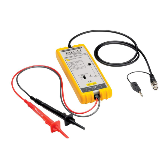
Page 10: Appearance
Differential Probes User’s Guide 4. Appearance TA041, TA042, TA043, TA044, and TA057 probes Sprung hooks The sprung hooks allow a safe connection to test points in the circuits under test. Input leads The input leads of the differential probe connect to the sprung hooks that are supplied with the probe. Probe body Attenuation ratio switch (some probes may have controls in a different configuration) Overrange indicator Output lead The BNC output connector and an auxiliary grounding terminal are connected to the oscilloscope. DC power socket, for use with TA531 USB to DC power lead. See Section 5 for more information on connecting power leads. Power switch Copyright © 2015–2023 Pico Technology Ltd DO241-3... -
Page 11: Ta531 Usb To Dc Power Lead
Differential Probes User’s Guide 5. TA531 USB to DC power lead TA531 USB to DC power lead To USB power supply Oscilloscope front panel 6. Overrange indicator The overrange indicator lights up red if the voltage of the input signal exceeds the linear operating range of the probe. When this happens, the signal on the probe output may not accurately represent the signal on the probe input. The overvoltage indicator is found on the front panel of the probe. DO241-3 Copyright © 2015–2023 Pico Technology Ltd... -
Page 12: Specifications
Differential Probes User’s Guide Copyright © 2015–2023 Pico Technology Ltd DO241-3... -
Page 13: Derating Curves
10000 1000 1000 1000 10 M 100 M Frequency (Hz) TA042 10000 1000 1000 1000 100 k 10 M 100 M Frequency (Hz) TA043 10000 1000 1000 1000 100 k 10 M 100 M Frequency (Hz) DO241-3 Copyright © 2015–2023 Pico Technology Ltd... -
Page 14: Test Procedure
2500 1000 100 k 100 M 10 M Frequency (Hz) 9. Test procedure Connect the BNC output connector to the vertical input of a general-purpose oscilloscope. Connect the probe to an appropriate power source, such as the mains adaptor or four AA cells. Turn on the probe using the power switch. Set the oscilloscope input to DC coupling and 1 V/div. Center the trace on the display. Connect the sprung hooks of the probe to the circuit under test. A 50 Hz or 60 Hz sine wave of proper amplitude will be displayed on the screen of the oscilloscope. This demonstrates that the probe is working properly. 10. Calibration There are three main sources of uncertainty when calibrating a Pico differential probe in addition to any uncertainty in the test setup. These are: The stated DC accuracy of the probe under test (see specifications table). Any DC offset or noise in the probe output. The values in this manual are typical, so to find the DC offset for a given unit a reading must be taken with the inputs to the probe shorted together. The AC performance of the probe. This is specified as being within 3 dB over the entire frequency range of the probe. Any absolute voltage accuracy testing must be done under DC conditions. One other possible cause of noise is the probe’s power source. It is recommended that, where possible, probes are calibrated using a battery supply rather than a mains supply unit. The adjustment procedure is available from Pico Technology on request. Copyright © 2015–2023 Pico Technology Ltd DO241-3... -
Page 15: Zero Probe Offset
Zero probe offset The probes can be adjusted for zeroing out the probe’s offset voltage using a trimmer tool supplied with the probe. Follow this procedure to perform the offset-zero calibration: 1. After turning on the power to the oscilloscope and probe, leave them on for >30 minutes to stabilize. You may use the USB power cord or batteries to power the probe. 2. Connect the probe to channel A of your oscilloscope. 3. Short the + and – probe inputs together with the hook tips. 4. Select Auto range in the oscilloscope software. 5. Then set units to Volt and select the lowest attenuation. 6. Set the ocsilloscope to DC coupled mode. 7. Position the ground of the waveform to the centre of the screen and set the vertical scale to 10 mV/div or 20 mV/div. 8. Set the oscilloscope to Averaging mode (x8 or higher) or High resolution mode to reduce scope noise. 9. Using the trimmer tool supplied with the probe, adjust the probe offset voltage to 0 V. Cleaning Only use a soft, damp cloth to clean the probe. WARNING To prevent injury or death, always ensure the probe is thoroughly dry after cleaning. CAUTION To prevent damage to the probe and other connected equipment, do not immerse the probe in any liquids. DO241-3 Copyright © 2015–2023 Pico Technology Ltd... - Page 16 Room 2252, 22/F, Centro Im Rehwinkel 6 568 Hengfeng Road 30827 Garbsen Zhabei District Germany Shanghai 200070 PR China +86 21 2226-5152 +49 (0) 5131 907 62 90 pico.china@picotech.com info.de@picotech.com Pico Technology is an internationally registered trade mark of Pico Technology Ltd. DO241-3. Copyright © 2015–2023 Pico Technology Ltd. All rights reserved. www.picotech.com...
Need help?
Do you have a question about the TA043 and is the answer not in the manual?
Questions and answers