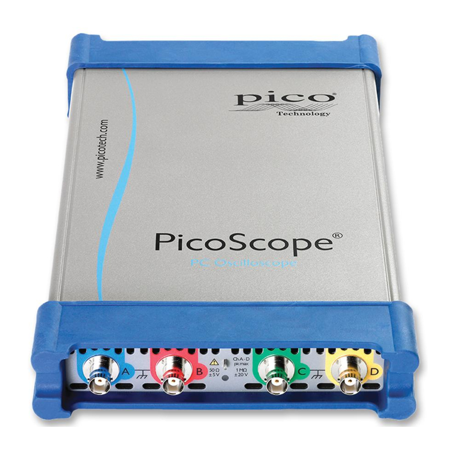
Summary of Contents for pico Technology PicoScope 6000 Series
- Page 1 Performance Verification Procedure PicoScope 6000 Series Oscilloscopes models PicoScope 6402, 6402A/B/C/D PicoScope 6403, 6403A/B/C/D PicoScope 6404, 6404A/B/C/D...
-
Page 2: Table Of Contents
Contents Introduction ..........................1 Equipment list ..........................1 PicoScope settings files ......................... 1 Check DC gain accuracy ......................2 Check timebase accuracy ......................6 Check channel bandwidth ......................7 Check trigger ..........................9 Check AUX input ......................... 9 Check input impedance (resistance) ..................10 10. -
Page 3: Introduction
If the measured value is outside the instrument’s specification, it should be returned to Pico Technology so that the calibration values can be updated or the unit repaired to bring the instrument within specification. 2. Equipment list... -
Page 4: Check Dc Gain Accuracy
Performance verification procedure 4. Check DC gain accuracy Equipment required Fluke 9500B Oscilloscope Calibrator Prerequisites Allow the instrument to stabilize in the laboratory for a period of not less than 30 minutes before any measurements are made. During the warm-up period the instrument must be set to free-running trigger, timebase to 10 ms and all channels switched on, with the scope running. - Page 5 DC gain accuracy 1 MΩ Add a ‘DC Average’ measurement to Channel A: In the menu bar, click Measurements > Add Measurement Set the channel to A Set the type of measurement to DC Average Click OK Apply voltages from Table 1 to the corresponding range. See Figure 1 for an example of the PicoScope display at this stage.
- Page 6 4.4.1 Channel A 1 MΩ input impedance Specified tolerance (%): 3% on all ranges Test Allowable Range voltage error Accuracy limits Average Pass/Fail (±volts) (volts) (±volts) (volts) 50 mV +40 mV 1.5 mV +38.5 mV to +41.5 mV 100 mV +90 mV 3 mV +87 mV to +93 mV...
- Page 7 4.4.3 Channel C 1 MΩ input impedance Specified tolerance (%): 3% on all ranges Test Allowable Range voltage error Accuracy limits Average Pass/Fail (±volts) (volts) (±volts) (volts) 50 mV +40 mV 1.5 mV +38.5 mV to +41.5 mV 100 mV +90 mV 3 mV +87 mV to +93 mV...
-
Page 8: Check Timebase Accuracy
5. Check timebase accuracy Equipment required Fluke 9500B Oscilloscope Calibrator Prerequisites See “Check DC gain accuracy”. Procedure Ensure the Fluke 9500B calibration generator is in Amplitude mode, and then set it for 0.8 V/div x 5, with the frequency set to 100 Hz. Connect the output to channel A Load settings “2 Timebase Accuracy”... -
Page 9: Check Channel Bandwidth
6. Check channel bandwidth Equipment required Fluke 9500B Oscilloscope Calibrator Prerequisites See “Check DC gain accuracy”. Procedure This test verifies the bandwidth performance of the product. The products should exceed specified bandwidth in this configuration. For this test the maximum sample rate of the device is required (5 GS/s) so only enable the channel under test. - Page 10 Pk-pk voltage Pk-pk voltage Pass Channel @ 50 kHz Pass/Fail criterion > 0.729 > 0.729 > 0.729 > 0.729 Table 7 Note 1: The pass criterion for is the voltage ratio corresponding to a 3 dB loss multiplied by the amplitude flatness error (±3%) of the Fluke 9500B in this frequency range assuming a load VSWR of 1.6:1: Reference: The Fluke 9500B Oscilloscope Calibrator (1626204 B-ENG-N A, DS255, 2001) PT-003545-DO-1.docx...
-
Page 11: Check Trigger
7. Check trigger Equipment required None Prerequisites None Procedure The trigger circuit is a digital trigger. Therefore it is not necessary to check the trigger sensitivity. 8. Check AUX input Spec of AUX input: ±1 V, 25 MHz Procedure Load front panel settings file “5 Aux Trigger” referred to above. Or use manual setup (see Appendix 4 –... -
Page 12: Check Input Impedance (Resistance)
9. Check input impedance (resistance) Spec of input resistance: 1 MΩ ± 1%, 50 Ω ± 2% Equipment required Fluke 9500B Oscilloscope Calibrator Prerequisites See “Check DC gain accuracy” Procedure Load settings file “6 Input Resistance” referred to above. Or use manual setup (see Appendix 5 – Input impedance) Connect the output of the oscilloscope calibrator to the Channel A input Set the impedance to 1 MΩ... - Page 13 Channel A Vertical 50 Ω input 50 Ω 1 MΩ input 1 MΩ range 49 Ω to 51 Ω Pass / Fail 0.99 MΩ to 1.01 MΩ Pass /Fail 50 mV 100 mV 200 mV 500 mV 10 V 20 V Table 8 Channel B Vertical...
- Page 14 Channel C Vertical 50 Ω input 50 Ω 1 MΩ input 1 MΩ range 49 Ω to 51 Ω Pass / Fail 0.99 MΩ to 1.01 MΩ Pass /Fail 50 mV 100 mV 200 mV 500 mV 10 V 20 V Table 10 Channel D Vertical...
-
Page 15: Check Probe Compensation Output
10. Check probe compensation output Apply the oscilloscope probe compensation output to Channel A using a x1 probe Set the voltage cursors to display the output voltage Use these cursors as a reference to a known DC voltage applied to Channel A Record the measured voltage in Table 12 below. -
Page 16: Appendix 1 - Dc Gain Accuracy Setup
Manual settings for PicoScope 6 If possible, use the settings files referred to above. Otherwise, PicoScope 6 can be configured manually as follows. Before starting any test, reset the oscilloscope with this procedure: Select File > Startup Settings > Reset Startup Settings Click the Home button 11.


Need help?
Do you have a question about the PicoScope 6000 Series and is the answer not in the manual?
Questions and answers