Table of Contents
Advertisement
Quick Links
Advertisement
Table of Contents

Related Manuals for Bauer POSEIDON PE 250-TE


Summary of Contents for Bauer POSEIDON PE 250-TE
- Page 2 OPERATING MANUAL A_002_en 2/150 28.08.2019...
-
Page 3: Table Of Contents
OPERATING MANUAL Table of contents Preface Manufacturer’s details .................... 9 1.1.1 Contact data BAUER KOMPRESSOREN ..............9 About this manual ....................10 1.2.1 Purpose of this manual ..................10 1.2.2 Contents of this manual ..................10 1.2.3 Target groups of this manual .................10 1.2.4... - Page 4 OPERATING MANUAL 2.6.3 Duties of the personnel ..................26 Safety regulations ....................27 Product description Structure and function ..................29 3.1.1 Structure ....................... 29 3.1.2 Function schematic ....................33 3.1.3 Functional principle ....................34 Display elements ....................36 3.2.1 Control system ......................36 3.2.2 B-TIMER display and operating elements .............. 37 3.2.3 B-SECURUS monitoring device ................38 Control elements ....................39...
- Page 5 OPERATING MANUAL 5.1.1 Checking the cargo ....................51 5.1.2 Preparing for transport ..................51 5.1.3 Transport .......................52 Storage and preservation ..................53 5.2.1 Selecting the storage location ................53 5.2.2 Preparing for preservation ..................53 5.2.3 Preservation ......................54 5.2.4 Inspecting the unit during storage ................ 54 Installation Preparing the installation site ................55 Installing the unit ....................
- Page 6 OPERATING MANUAL 8.1.5 Error display B-TIMER ....................81 Maintenance Evidence of maintenance ..................83 Maintenance table ....................83 Resources for maintenance and repairs ..............84 9.3.1 Bolt torques ......................84 9.3.2 Bolt tightening sequence ..................85 9.3.3 Lubricant .......................85 9.3.4 Lubrication oil ....................... 86 9.3.5 Adhesive and sealant ....................
- Page 7 OPERATING MANUAL 9.12.2 Adjusting the timer ..................... 113 9.13 Maintenance activities electrical system ............115 9.13.1 Maintaining the electrical control systems ............115 9.13.2 Adjusting the final pressure switch ..............116 9.13.3 Replace the battery of the B-TIMER ..............116 9.14 Maintenance activities drive system ..............
- Page 8 OPERATING MANUAL A_002_en 8/150 28.08.2019...
-
Page 9: Preface
OPERATING MANUAL Preface | 1 1 Preface 1.1 Manufacturer’s details 1.1.1 Contact data BAUER KOMPRESSOREN BAUER KOMPRESSOREN GmbH Stäblistr. 8 D-81477 Munich Tel.: +49 89 7 80 49-0 Fax: +49 89 7 80 49-167 www.bauer-kompressoren.de info@bauer-kompressoren.de A_002_en 28.08.2019 9/150... -
Page 10: About This Manual
Chapter 11.1, Page 123 and the following. All the information in this manual is correct at the time of printing. BAUER KOMPRESSOREN reserves the right to make technical changes that facili- tate an improvement or raise the safety standard. 1.2.3... -
Page 11: Symbols Used
OPERATING MANUAL Preface | 1 1.2.4 Symbols used The following symbols are used in the manual: Symbol Meaning Dangers for persons. For more information, Chapter 2.3 Display and meaning of warn- ings, Page Information for understanding or optimising the work processes. Information for solving problems or for trou- bleshooting. -
Page 12: About This Product
1 | Preface OPERATING MANUAL 1.3 About this product 1.3.1 Identifying the product This manual is applicable for the models and series specified on the title page. • Take the exact model and serial number from the type plate and enter into the figure below. -
Page 13: Variants
OPERATING MANUAL Preface | 1 1.3.4 Variants Equipment features PE 200-TB PE 250-TB PE 300-TB Delivery volume [l/ min] Cylinder fillings per hour (10 l / 0-200 bar) Tab. 2 Compressor units with petrol engine Equipment features PE 200-TE PE 250-TE PE 300-TE Delivery volume [l/ min]... -
Page 14: Options
Chapter 11.1 Declaration of conformity, Page 123. CE mark With the EC mark affixed on the product, BAUER KOMPRESSOREN declares that the product satisfies the application requirements specified in the harmonisation legislation of the European Community provided for its affixing. -
Page 15: For Your Safety
OPERATING MANUAL For your safety | 2 2 For your safety 2.1 Intended usage The machine is intended exclusively for the compression and the storage of the medium specified, under consideration of the conditions specified, see Technical Data. Proper use also includes: •... -
Page 16: Display And Meaning Of Warnings
2 | For your safety OPERATING MANUAL 2.3 Display and meaning of warnings 2.3.1 Hazard classes Important instructions regarding personal protection and safe operation are indica- ted in the manual in distinct hazard classes. The hazard classes explain how states or individual steps of an operation sequence are dangerous and can cause dam- age. -
Page 17: Danger Warnings On The Machine
OPERATING MANUAL For your safety | 2 2.3.3 Danger warnings on the machine Depending on the construction and purpose of use, the following indications are affixed to the machine and included in the manual; these indications point to po- tential dangers: Symbol Meaning Caution, automatic control! -
Page 18: Product Safety
2 | For your safety OPERATING MANUAL 2.4 Product safety 2.4.1 Fundamental safety information Fundamental dangers The following safety measures always include: • The machine should only be used in a technically perfect condition and in an intended, safety and danger-aware method, taking into account the operating instructions. -
Page 19: Safety Instructions Regarding Transport And Loading Work
OPERATING MANUAL For your safety | 2 Danger due to gas, dust and smoke • When working with smothering gases, you must monitor the oxygen concen- tration in the room using a mobile gas measuring device. • When working in confined spaces, ensure adequate ventilation and follow ex- isting national regulations where applicable. -
Page 20: Safety Information Regarding Operation
2 | For your safety OPERATING MANUAL 2.4.3 Safety information regarding operation Carry out the following measures to ensure safe operation: • Refrain from any working practices which may compromise safety. • Only operate the machine if all protection equipment and safety-related equip- ment (e.g. -
Page 21: Safety Instructions Regarding Maintenance, Service And Repairs
OPERATING MANUAL For your safety | 2 2.4.4 Safety instructions regarding maintenance, service and repairs Carry out the following measures for ensuring safe maintenance, service and repair work: • For all work that affects the operation, adjustment of production capacities, changeover or setting of the machine and its safety-relevant equipment and inspection, maintenance and repair, observe the switching on and switching off procedures in accordance with the operating instructions and instructions... -
Page 22: Particular Dangers
2 | For your safety OPERATING MANUAL 2.4.6 Particular dangers Safe handling of pressure vessels There are two types of pressure vessels: • Pressure vessels for static load: The pressure vessels are under virtually con- stant operating pressure, and the pressure fluctuations are very small. Pres- sure vessels for static load are not specially marked and can be operated as long as no safety-relevant faults are found during the regular vessel repeat testing procedures. -
Page 23: Instructions Regarding Emergency
OPERATING MANUAL For your safety | 2 Instructions regarding handling combustion engines Follow the following instructions to ensure the safety of the users: • Do not inhale the exhaust gases. • Combustion engines should never be operated in closed rooms. •... -
Page 24: Organisational Duties
2 | For your safety OPERATING MANUAL 2.6 Organisational duties 2.6.1 Duties of the operating company The operating company is responsible for the intended use of the machine. • Keep the instruction manual to hand near the machine and must be available to the personnel at all times. -
Page 25: Personnel Selection And Qualification
Ensure that only trained personnel operate the machine. • Ensure that only the service personnel trained and authorised by BAUER KOMPRESSOREN carry out the assembly and installation activities. • Ensure that only competent personnel carry out the first commissioning and recurrent tests. -
Page 26: Duties Of The Personnel
2 | For your safety OPERATING MANUAL 2.6.3 Duties of the personnel The personnel must comply with the following safety requirements: • Read and understand the operating instruction manual. • Refrain from any working practices which may compromise safety. • Use personal protection equipment if required. -
Page 27: Safety Regulations
OPERATING MANUAL For your safety | 2 2.7 Safety regulations The following list of safety regulations does not claim to be exhaustive and up-to- date, and is applicable only for the Federal Republic of Germany. • Ensure that the equivalent provisions of the operator’s country are observed. •... - Page 28 For further instructions for the licensing process and the testing of filling stations before commissioning, refer to the information sheet (can be obtained from BAUER KOMPRESSOREN). The test certificates and documents supplied with the compressor are important and must be included in the application documents as part of the licensing proc- ess.
-
Page 29: Product Description
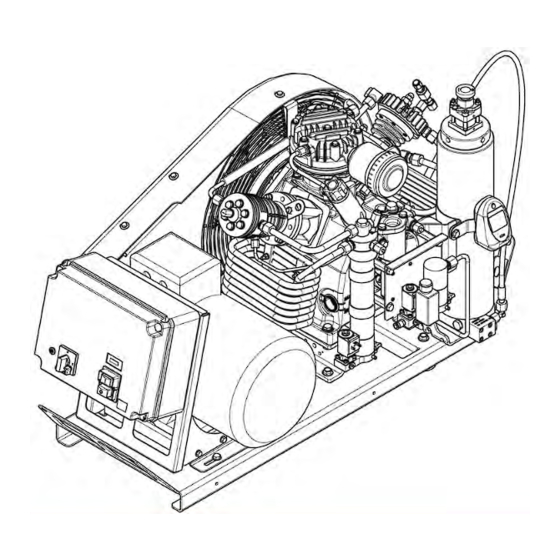
OPERATING MANUAL Product description | 3 3 Product description 3.1 Structure and function 3.1.1 Structure Fig. 2 Structure PE 300-TE with switch-over device Compressor block Drive motor 11 Switch-over device (option) Belt guard Condensate drain cock, inter- 12 Filter system P21 mediate separator Motor protection switch (option) Filling device with pressure... - Page 30 3 | Product description OPERATING MANUAL Fig. 3 Structure PE 250-TE with compressor control system, filter system P21 and switch-over device Compressor block Drive motor 11 Switch-over device (option) Belt guard Condensate drain valve (option), 12 Filter system P21 intermediate separator Compressor control system (op- Condensate drain valve (option), 13 Final pressure safety valve...
- Page 31 OPERATING MANUAL Product description | 3 Fig. 4 Structure PE 250-TB, filter system P31 and B-TIMER Compressor block Carrier frame Trolley (option) Belt guard Condensate vessel 10 Filter system P31 (option) Petrol tank Filling device with pressure 11 B-TIMER (option) gauge Exhaust Switch-over device (option)
- Page 32 3 | Product description OPERATING MANUAL Fig. 5 Structure PE 300-TE with compressor control system, filter system P41 and B-SECURUS monitoring device Compressor block Condensate drain valve (option), 13 Pressure retaining/non-return intermediate separator valve Belt guard Filter system P41 (option) 14 Pressure outlet Compressor control system (op- Final separator...
-
Page 33: Function Schematic
OPERATING MANUAL Product description | 3 3.1.2 Function schematic The function schematic shows the route of the air through the compressor unit. The type and scope of the components depend on the unit configuration, the func- tional principle and arrangement of the components remain the same, however. Fig. -
Page 34: Functional Principle
3 | Product description OPERATING MANUAL 3.1.3 Functional principle Intake The compressor unit draws the medium to be compressed or the air via the intake filter. This contains a replaceable filter insert for removing the solid particles from the drawn-in medium. Compression Compression takes place in the compressor block. - Page 35 OPERATING MANUAL Product description | 3 Control and monitoring Operation and switching the unit on and off is carried out, as standard, manually using the motor protection switch. The electrical control system (option) permits semi-automatic operation of the compressor unit, depending on the filling pressure. Monitoring the filling pressure is via the pressure switch.
-
Page 36: Display Elements
3 | Product description OPERATING MANUAL 3.2 Display elements 3.2.1 Control system Fig. 7 Display elements Operating hours counter Signal lamp, monitoring the direction of rotation A_002_en 36/150 28.08.2019... -
Page 37: B-Timer Display And Operating Elements
OPERATING MANUAL Product description | 3 3.2.2 B-TIMER display and operating elements 654321 Fig. 8 Display and operating elements Display of due maintenance Input key Display of low battery status Display of cartridge saturation Display of operating hours or car- Display of due maintenance type or tridge number the setup menu... -
Page 38: B-Securus Monitoring Device
3 | Product description OPERATING MANUAL 3.2.3 B-SECURUS monitoring device Fig. 9 Display elements of the B-SECURUS monitoring device Cartridge or unit con- Relay 1 Relay 2 Relay 3 dition Contact 4-5 Contact 4-6 Contact 4-7 1, "Failure" Compressor switch off open closed open... -
Page 39: Control Elements
OPERATING MANUAL Product description | 3 3.3 Control elements 3.3.1 Control system Fig. 10 Control elements Main switch On/off button A_002_en 28.08.2019 39/150... -
Page 40: Filling Equipment
3 | Product description OPERATING MANUAL 3.3.2 Filling equipment Fig. 11 Filling equipment Filling cock International bracket connection, 200 bar Filling connection Filling pressure gauge 3.4 Operating modes 3.4.1 Manual After switching the compressor on manually, this must then also be switched off again manually. -
Page 41: Technical Data
OPERATING MANUAL Technical data | 4 4 Technical data 4.1 Technical data compressor unit 4.1.1 Technical data PE 200-TB Category and unit Value Performance characteristics Medium Intake pressure atmospheric Operating pressure max. [bar] Blow-off pressure, final pressure safety valve 225 / 330 [bar] Switch-off pressure [bar] 220 / 320... - Page 42 4 | Technical data OPERATING MANUAL Category and unit Value Emissions Noise pressure level [dB(A)] in accordance with DIN EN ISO 2151 at 1m distance Noise level [dB(A)] A_002_en 42/150 28.08.2019...
-
Page 43: Technical Data Pe 200-Te
OPERATING MANUAL Technical data | 4 4.1.2 Technical data PE 200-TE Category and unit Value Performance characteristics Medium Intake pressure atmospheric Operating pressure max. [bar] Blow-off pressure, final pressure safety valve 225 / 330 [bar] Switch-off pressure [bar] 220 / 320 Setting pressure, pressure maintaining/non- return valve [bar] Setting times of automatic condensate drain,... -
Page 44: Technical Data Pe 250-Tb
4 | Technical data OPERATING MANUAL 4.1.3 Technical data PE 250-TB Category and unit Value Performance characteristics Medium Intake pressure atmospheric Operating pressure max. [bar] Blow-off pressure, final pressure safety valve 225 / 330 [bar] Switch-off pressure [bar] 220 / 320 Setting pressure, pressure maintaining/non- return valve [bar] Setting times of automatic condensate drain,... -
Page 45: Technical Data Pe 250-Te
OPERATING MANUAL Technical data | 4 4.1.4 Technical data PE 250-TE Category and unit Value Performance characteristics Medium Intake pressure atmospheric Operating pressure max. [bar] Blow-off pressure, final pressure safety valve 225 / 330 [bar] Switch-off pressure [bar] 220 / 320 Setting pressure, pressure maintaining/non- return valve [bar] Setting times of automatic condensate drain,... -
Page 46: Technical Data Pe 300-Tb
4 | Technical data OPERATING MANUAL 4.1.5 Technical data PE 300-TB Category and unit Value Performance characteristics Medium Intake pressure atmospheric Operating pressure max. [bar] Blow-off pressure, final pressure safety valve 225 / 330 [bar] Switch-off pressure [bar] 220 / 320 Setting pressure, pressure maintaining/non- return valve [bar] Setting times of automatic condensate drain... -
Page 47: Technical Data Pe 300-Te
OPERATING MANUAL Technical data | 4 4.1.6 Technical data PE 300-TE Category and unit Value Performance characteristics Medium Intake pressure atmospheric Operating pressure max. [bar] Blow-off pressure, final pressure safety valve 225 / 330 [bar] Switch-off pressure [bar] 220 / 320 Setting pressure, pressure maintaining/non- return valve [bar] Setting times of automatic condensate drain... -
Page 48: Technical Data Compressor Block
4 | Technical data OPERATING MANUAL 4.2 Technical data Compressor block 4.2.1 Technical data compressor block IK120 Category and unit Value Number of stages Number of cylinders Cylinder bore 1st stage [mm] Cylinder bore 2nd stage [mm] Cylinder bore 3rd stage [mm] Piston stroke [mm] Direction of rotation (looking onto the fly- left... -
Page 49: Technical Data Filter System
OPERATING MANUAL Technical data | 4 4.3 Technical data Filter system 4.3.1 Technical data about the filter system P21 Filter system Value Operating pressure max. [bar] Pressure dew-point [°C] <-20 °C, corresponding to 3 mg/m at 300 Filter content [l] 0.57 Classification as per the Pressure Equipment Vessel category II... -
Page 50: Technical Data Filter System P41
4 | Technical data OPERATING MANUAL 4.3.3 Technical data filter system P41 Category and unit Value Number of cartridge filters Operating pressure max. [bar] 350 / 420 / 550 Operating pressure min. [bar] Deployment temperature range [°C] +5 ... +50 Residual water content max. -
Page 51: Transport And Storage
2. Check the delivered item immediately for transport damage. 3. Check the delivered item immediately against the packing lists for to ensure completeness. 4. Report any irregularities to BAUER KOMPRESSOREN immediately. Complaints made later cannot be considered. 5. Never put the machine into operation if it is damaged. -
Page 52: Transport
5 | Transport and storage OPERATING MANUAL 5.1.3 Transport WARNING Danger of crushing due to falling, tilting or swinging loads! Crushing can result in death or serious injuries. Follow the safety instructions and safety regulations when transporting the machine. Follow the transport instructions. Keep in mind the transport weights and measurements. -
Page 53: Storage And Preservation
OPERATING MANUAL Transport and storage | 5 5.2 Storage and preservation 5.2.1 Selecting the storage location Ensure that the storage space fulfils the following conditions: dry, frost-free, vi- bration-free. Covering with plastic sheets is recommended only if it prevents condensation from being formed. -
Page 54: Preservation
5.2.3 Preservation If the unit has to be stored for more than 2 years, request special instructions from BAUER KOMPRESSOREN, see Chapter 1.1.1 Contact data BAUER KOMPRESSOREN, Page If the unit is put out of operation for more than 6 months, preserve it as follows: 1. -
Page 55: Installation
OPERATING MANUAL Installation | 6 6 Installation 6.1 Preparing the installation site 1. Make sure that the installation site complies with the required ambient condi- tions, see technical data. 2. Make sure that the surface is flat and clean. 3. Make sure that the surface can support the weight of the machine and that the machine is stable. -
Page 56: Installing The Unit
6 | Installation OPERATING MANUAL 6.2 Installing the unit 6.2.1 Installing the unit DANGER Danger of poisoning due to pollutants in breathing air! Units with petrol engines should never be operated in closed rooms! When filling breathing air cylinders using petrol units, each filled cylinder must be CO checked since, even with careful handling and the use of special car- tridges with a catalytic converter (CO filter cartridges), contamination of the compressed air cannot be ruled out. - Page 57 OPERATING MANUAL Installation | 6 Installation of unit outdoors DANGER Danger of poisoning! Exhaust gases could get drawn in if there is no wind or swirling winds. This may lead to fatal concentrations of CO in the cylinder. Do not fill cylinders if there is a possibility that exhaust gases could be drawn Check the concentration of CO in the compressed air using a suitable gas measuring instrument.
-
Page 58: Electrical Connection Of The Unit
6 | Installation OPERATING MANUAL Fig. 13 Installation of a unit with a petrol engine 4. Install the unit with respect to the wind direction so that the exhaust gases are not drawn in. If the wind changes you must turn the unit accordingly. 6.3 Electrical connection of the unit DANGER Danger to life due to electric voltages! -
Page 59: Having The Unit Accepted
OPERATING MANUAL Installation | 6 6.4 Having the unit accepted At the BAUER KOMPRESSOREN factory, components such as the compressor, storage system and other accompanying assemblies are subjected to a technical partial acceptance inspection by the TÜV. Before commissioning the unit, have it inspected at the installation site by a qualified person or authorised inspection agency, see Chapter 2.7 Safety regu-... - Page 60 6 | Installation OPERATING MANUAL A_002_en 60/150 28.08.2019...
-
Page 61: Commissioning And Operation
4. Perform a visual inspection of all components. If there are any irregularities, switch off the unit immediately and locate and rectify any errors or get in touch with the BAUER customer service department, see Chapter 1.1.1 Con- tact data BAUER KOMPRESSOREN, Page 5. -
Page 62: Commissioning The Unit For The First Time
7 | Commissioning and operation OPERATING MANUAL 7.1.2 Commissioning the unit for the first time All compressor units are checked before delivery in the factory so that commis- sioning can be carried out after proper erection, installation and successful accept- ance tests. - Page 63 9. Observe the pressure build-up in the unit properly. If there are any irregulari- ties, switch off the unit immediately and locate and rectify any errors or get in touch with the BAUER customer service department, see Chapter 1.1.1 Con-...
-
Page 64: Commissioning The Unit After Longer Downtimes
7 | Commissioning and operation OPERATING MANUAL 7.1.3 Commissioning the unit after longer downtimes 1. Please see chapter “Checks before each commissioning”. 2. Treat the motor in accordance with the instructions provided by the motor manufacturer. 3. After an extended period of storage, or after a standstill time of more than 2 years: the oil should be drained off and replaced with fresh oil, see Chap- ter 9.4 Maintenance activities - Lubricating oil system, Page... -
Page 65: Checking The Direction Of Rotation Of The Motor
OPERATING MANUAL Commissioning and operation | 7 7.1.4 Checking the direction of rotation of the motor DANGER Danger to life due to electric voltages! Contact with live parts leads to death or serious injuries. Work on the electrical unit may be carried out by an electrician only. Make sure that the unit is tension-free for the necessary work. -
Page 66: Preparing For The Operation With B-Timer
7 | Commissioning and operation OPERATING MANUAL 7.1.5 Preparing for the operation with B-TIMER 1. Ensure that the compressor’s pressure retention valve is set to 160 bar and that it is functioning correctly. Otherwise, the operation detection and the dis- play of filter capacity do not function correctly. -
Page 67: Operation
OPERATING MANUAL Commissioning and operation | 7 7.2 Operation CAUTION Danger of injury due to automatic re-start of the unit! The unit can re-start automatically depending on the version. Follow the safety instructions for the unit. Operate the unit only if the safety devices are installed. Ensure that a suddenly restarted unit does not pose dangers to people or the machine. -
Page 68: Switching On The Unit
7 | Commissioning and operation OPERATING MANUAL 7.2.1 Switching on the unit 1. On units without automatic condensate drain: Open the condensate drain cocks to allow the pressure to dissipate and to allow the engine to start under zero load. The compressor is automatically unloaded on units with automatic condensate drain. -
Page 69: Switching The Unit Off
OPERATING MANUAL Commissioning and operation | 7 The unit is ready for filling. Ä 7.2.2 Switching the unit off 1. Close filling valve. 2. For units with electric motor: Set main switch to 0. - Or - For units with petrol engine: Set the ignition switch to 0 and close the fuel tap. 3. -
Page 70: Behaviour In Case Of Emergency
7 | Commissioning and operation OPERATING MANUAL 7.2.4 Behaviour in case of emergency Switch off units with electric motor in the event of an emergency Pull out the mains plug. - Or - Set the motor protection switch or main switch to 0. The unit stops operation and switches to a safe condition. -
Page 71: Operating The B-Timer
OPERATING MANUAL Commissioning and operation | 7 7.2.5 Operating the B-TIMER 654321 Fig. 17 Display and operating elements Display of due maintenance Input key Display of low battery status Display of cartridge saturation Display of operating hours or car- Display of due maintenance type or tridge number the setup menu Selection key... - Page 72 7 | Commissioning and operation OPERATING MANUAL Toggling the display The B-TIMER shows the following information: • Main menu • Remaining filter capacity in percent • Number of operating hours until service interval A (500 hours or yearly) • Number of operating hours until service interval B (1000 hours or every 2 years) •...
- Page 73 OPERATING MANUAL Commissioning and operation | 7 Setting the B-TIMER The following values can be set on the B-TIMER: • Enter the numbers of filter cartridges used • Set the delivery volume • Set the operating pressure • Set the operating hours After changing the set values, the B-TIMER must be reset.
- Page 74 7 | Commissioning and operation OPERATING MANUAL Setting the delivery volume 1. In the setup mode, press the selection key until the corresponding sub-menu is reached. The filter icon blinks and “B" is shown. Ä 2. Refer to the order documents for the delivery volume of the compressor in l/ min.
-
Page 75: Filling Operation
OPERATING MANUAL Commissioning and operation | 7 7.2.6 Filling operation DANGER Danger of poisoning due to pollutants in breathing air! Inhaling harmful gases can be dangerous to life. Make sure that the air drawn in is free from toxic gases, exhaust gases or sol- vent vapours. - Page 76 7 | Commissioning and operation OPERATING MANUAL Filling the compressed air cylinders WARNING Danger of injuries due to the use of non-approved or damaged filling equip- ment and compressed air cylinders! Unsuitable or damaged material may burst or tear under pressure. Use only approved filling devices and compressed air cylinders.
- Page 77 OPERATING MANUAL Commissioning and operation | 7 3. Open cylinder cock. The compressed air cylinder is filled. Ä 4. Close the cylinder cock once the final pressure is reached. 5. Close filling cock. 6. Remove the compressed air cylinder. During filling, the compressed air cylinder heats up because of the subsequent compression in the compressed air cylinder.
- Page 78 7 | Commissioning and operation OPERATING MANUAL Switching over the filling pressure NOTICE Danger of damage when switching over the filling pressure! The switching over of the filling pressure damages the valve if it is under pressure. Do not actuate the switch-over device during the filling process. Depressurise the unit before actuating the switch-over device, see Chap- ter 9.6.3, Page...
-
Page 79: Troubleshooting
OPERATING MANUAL Troubleshooting | 8 8 Troubleshooting 8.1 Fault finding and fault correction 8.1.1 Fault finding in drive motor Description Cause Rectification Motor does not start. Fault in the electrical power Check lines and fuses. Com- supply. pare the motor data with the mains supply. -
Page 80: Fault Finding In Automatic Condensate Drain
8 | Troubleshooting OPERATING MANUAL 8.1.3 Fault finding in automatic condensate drain Description Cause Rectification Inadequate water removal or Opening time or cycle time of check the set opening time or much condensate coming out solenoid valve set incorrectly cycle time at the timer and (>40 ml at function check) have it adjusted if necessary Solenoid valve does not open... -
Page 81: Fault Finding In Electrical Control System
Error display B-TIMER Description Cause Rectification "Error 1" or "Error 2" is shown Temperature sensor defec- B-TIMER must not be used on the display. tive. any longer. BAUER Contact the Customer Service and get the device repaired. A_002_en 28.08.2019 81/150... - Page 82 8 | Troubleshooting OPERATING MANUAL A_002_en 82/150 28.08.2019...
-
Page 83: Maintenance
In the event of warranty claims being made, the maintenance booklet will help you to prove that this work has been carried out and that damage cannot be attributed to inadequate maintenance. BAUER KOMPRESSOREN refers to its General Terms and Conditions. -
Page 84: Resources For Maintenance And Repairs
9 | Maintenance OPERATING MANUAL 9.3 Resources for maintenance and repairs 9.3.1 Bolt torques Unless otherwise stated, the following torques must be used. The specified values apply to greased bolts. Valve head screws must be tightened with a torque wrench. Self-locking nuts must not be re-used, replace them. -
Page 85: Bolt Tightening Sequence
Bolt tightening sequence 9.3.3 Lubricant Application range Lubricant Rubber parts, plastic parts, thread of the filter BAUER special grease, order number N19752 housing (container - 350 g) BAUER special grease, order number 072500 (container - 3 g) O-rings BAUER special grease, order number 072500... -
Page 86: Lubrication Oil
• good corrosion protection • emulsification of condensed water in crankcase To ensure perfect operation, BAUER KOMPRESSOREN recommends using only those oils listed in this operating instructions and that have been tested and ap- proved by us. A_002_en 86/150... - Page 87 The exclusive use of high-quality branded oils is essential because of the thermal loads encountered in the compressor. In order to ensure perfect operation, we rec- ommend using only those oils listed below from BAUER in the quoted operating conditions tested and approved by us.
-
Page 88: Adhesive And Sealant
9 | Maintenance OPERATING MANUAL 9.3.5 Adhesive and sealant Application range Adhesive or sealant High-strength bolt locking, gluing in of threa- Order number N25834 (50 ml) ded studs Medium strength bolt locking Order number N28220-S02 (50 ml) Thread sealing cord, sealing of conical threads Order number N42644 Temperature-resistant silicone sealant, metal- Order number N18247 (50 g) on-metal sealing, high-temperature bonds,... -
Page 89: Filter Cartridges
OPERATING MANUAL Maintenance | 9 9.3.7 Filter cartridges Filter cartridges for the breathing air application P21 Order number Filter system Filtration of SECURUS monitor- 057679 O/Oil 059183 O/Oil/CO Filter cartridges for the breathing air application P31 Order number Filter system Filtration of SECURUS moni- Length [inch]... -
Page 90: Maintenance Activities - Lubricating Oil System
9 | Maintenance OPERATING MANUAL 9.4 Maintenance activities - Lubricating oil system CAUTION Danger of burns! Even after switching off the unit, pressure lines, heat exchangers, compressors, condensate valves, oil and possibly cooling water can be at high temperatures. There is a danger of burns if they are touched! Wear appropriate personal protection equipment or gloves. -
Page 91: Oil Change
OPERATING MANUAL Maintenance | 9 9.4.2 Oil change CAUTION Danger of burns! Even after switching off the unit, pressure lines, heat exchangers, compressors, condensate valves, oil and possibly cooling water can be at high temperatures. There is a danger of burns if they are touched! Wear appropriate personal protection equipment or gloves. - Page 92 9 | Maintenance OPERATING MANUAL Draining the oil Unit is at operating temperature. Suitable container is available for collecting the oil. Fig. 22 Draining the oil Oil filler spigot Oil drain cock 1. Open oil filler spigot. 2. Open the oil drain cock and collect the oil in a suitable container. If the red plastic handle of the oil drain cock is damaged or lost, the cock can be opened using the cover cap.
- Page 93 OPERATING MANUAL Maintenance | 9 NOTICE Environmental damage caused by improper disposal of waste oil! Dispose of used oil as special waste. Be mindful of the local regulations relating to the disposal of special waste. 8. Dispose of used oil. Changing the oil filter The required replacement parts are available.
-
Page 94: Changing The Oil Type
Filling oil NOTICE Risk of damage when changing the oil type! Before changing the oil type note the chapter "Oil change". Suitable BAUER compressor oil is available, seeChapter 9.3.4 Lubrication oil, Page 86 . Refer to technical data for the required quantity. -
Page 95: Venting The Oil Pump
OPERATING MANUAL Maintenance | 9 9.4.4 Venting the oil pump If no oil pressure builds up after the compressor starts running, the oil pump may need to be vented. This is particularly applicable after maintenance and servicing work, or if the unit was operated in conjunction with an incorrect rotational direc- tion. -
Page 96: Maintenance Activities - Intake Section
9 | Maintenance OPERATING MANUAL 9.5 Maintenance activities - Intake section 9.5.1 Replacing the suction filter The maintenance intervals are dependent on the condition of the air being drawn in. If there is a lot of dust it may be necessary to carry out maintenance monthly or weekly. -
Page 97: Maintenance Activities Filter System
OPERATING MANUAL Maintenance | 9 9.6 Maintenance activities filter system 9.6.1 General maintenance advices WARNING Risk of damages and injuries during maintenance! When disregarding the maintenance instructions, injuries and/or damages may occur. Observe following advices: Depressurise system before starting any maintenance work. Replace tilter cartridges in time. -
Page 98: Checking The Load Cycles
9 | Maintenance OPERATING MANUAL 9.6.2 Checking the load cycles The separators and filters are dynamically loaded and need to be checked and, if necessary, replaced at set intervals and number of load cycles. The load cycles of the filter depend on the operating conditions and will need to be determined individually. -
Page 99: Pressurising The Unit
OPERATING MANUAL Maintenance | 9 9.6.3 De-pressurising the unit CAUTION Increased noise level! Danger of acute hearing damage or noise-related hearing impairment! Wear ear defenders. The unit is switched off. 1. Open all the condensate drain cocks. 2. Secure the filling valve, point it downwards and open it slowly. 3. -
Page 100: Determine The Cartridge Service Life
9.6.4 Determine the cartridge service life In case of units without filter monitoring, BAUER recommends the use of the BAUER KOMPRESSOREN APP (B-APP) and of the contained calculation tool for the determination of the cartridge service life. The calculation tool takes into account a variety of parameters and thus enables a precise determination of the service life. - Page 101 OPERATING MANUAL Maintenance | 9 Determine cartridge service life on the basis of tables The number of operating hours or the number of possible cylinder fillings per filter cartridge can be determined using the tables in the appendix, with due regard to the ambient temperature and the cartridge being used.
- Page 102 9 | Maintenance OPERATING MANUAL Determining the cartridge service life in hours The cartridge service life values and the maximum number of operating hours per filter cartridge or cartridge combination is to be determined as follows: Cartridge Life time [hours] Filling pressure p = Delivery [l/min] 200 bar...
-
Page 103: Changing The Cartridge Of The Purifier
OPERATING MANUAL Maintenance | 9 9.6.5 Changing the cartridge of the purifier When the system has been used for the maximum permissible number of operating hours, change the cartridge as follows. Vacuum packing of the cartridge is undamaged. Special filter spanner (part of the scope of supply). ... - Page 104 9 | Maintenance OPERATING MANUAL Fig. 27 Filtersystem P21 and P31: Changing the cartridge Special tool Filter head Cartridge Fig. 28 Filtersystem P41: Changing the cartridge Special tool Filter head Cartridge 3. Use the special filter spanner tool to unscrew and remove the filter head. 4.
- Page 105 OPERATING MANUAL Maintenance | 9 9. Screw in the filter head manually, and use the special wrench to tighten it. Maximum torque: 1 Nm NOTICE Environmental damage caused by improper disposal of filter cartridges! Dispose of saturated filter cartridges as special waste. Be mindful of the local regulations relating to the disposal of special waste.
-
Page 106: Maintenance Activities Pressure Retention Valve
9.7.2 Adjusting the pressure retention valve The pressure retention valves may only be adjusted by trained personnel. For more information, contact the BAUER customer service department, see Chapter 1.1.1 Contact data BAUER KOMPRESSOREN, Page 1. Disengage locknuts (if they are present). -
Page 107: Maintenance Activities For Filling Equipment
The testing period for hose lines must be determined by operators as per the stipu- lations of the locally applicable regulations (the Industrial Safety Regulation applies in Germany). The hose lines must be tested by a competent person. Based on the German regulations, Bauer recommends the following testing periods for compressors: •... -
Page 108: Maintaining The Filling Valves
9 | Maintenance OPERATING MANUAL 9.8.2 Maintaining the filling valves A sintered filter in the filling valve body protects the filling valve from contamina- tion. Dismantle and clean the sintered filter of the filling valve as follows; in case of se- vere contamination, replace it if necessary: The compressor unit is switched off. -
Page 109: Maintenance Activities Safety Valves
• The blow-off pressure of the safety valves must be checked at regular inter- vals. The country-specific statutory stipulations apply to the test intervals. BAUER KOMPRESSOREN however recommends an annual check of the safety valves. • If a check of the response pressure is impossible for technical reasons, the safety valves will need to be replaced. -
Page 110: Maintenance Activities Pressure Gauge
Pressure gauges must be checked in accordance with the maintenance schedule. Using a special testing pressure gauge is recommended for checking the pressure gauges, see BAUER KOMPRESSOREN catalogue of high-pressure accessories. Allowances should be made for minor deviations during operation. If the pressure gauge shows large inaccuracies, however, it will need to be replaced. -
Page 111: Maintenance Activities - Intake Valves And Pressure Valves
9.11.2 Replacing the suction valves and pressure valves Only competent personnel may replace the valves of the compressor. For more in- formation, contact the BAUER customer service department, see Chapter 1.1.1 Contact data BAUER KOMPRESSOREN, Page NOTICE Material damage due to dissimilar suction and pressure valves! Replace the suction and pressure valves only in sets. -
Page 112: Maintenance Activities - Automatic Condensate Drain
9 | Maintenance OPERATING MANUAL 9.12 Maintenance activities - Automatic condensate drain 9.12.1 Check function of the automatic condensate drain WARNING Danger of injury for compressed gas escaping! Wear protective goggles and personal ear defenders. CAUTION Danger of burns! Even after switching off the unit, pressure lines, heat exchangers, compressors, condensate valves, oil and possibly cooling water can be at high temperatures. -
Page 113: Adjusting The Timer
Maintenance | 9 9.12.2 Adjusting the timer Only competent personnel may set the timer. For more information, contact the BAUER customer service department, see Chapter 1.1.1 Contact data BAUER KOMPRESSOREN, Page NOTICE Material damage due to unsuitable condensate drain intervals! Excessively short condensate drain intervals lead to the flooding of the separator and damage the downstream units. - Page 114 9 | Maintenance OPERATING MANUAL Fig. 31 Adjustment of DIP switch 2. Ensure that all DIP switches are set to OFF. 3. Set DIP switches 3 and 8 to ON, see part A. This switch-over allows determining the drain interval in a setting range Ä...
-
Page 115: Maintenance Activities Electrical System
OPERATING MANUAL Maintenance | 9 9.13 Maintenance activities electrical system 9.13.1 Maintaining the electrical control systems DANGER Danger to life due to electric voltages! Contact with live parts leads to death or serious injuries. Work on the electrical unit may be carried out by an electrician only. Make sure that the unit is tension-free for the necessary work. -
Page 116: Adjusting The Final Pressure Switch
9.13.3 Replace the battery of the B-TIMER The battery (BAUER order number: 82743) is placed in the battery compartment. A battery symbol is used to indicate that the battery is weak and must be replaced. The data is saved and is not lost when the battery is replaced. -
Page 117: Maintenance Activities Drive System
OPERATING MANUAL Maintenance | 9 9.14 Maintenance activities drive system 9.14.1 Electric motor maintenance 1. Clean the exterior of the electric motor on an occasional basis. 2. Be mindful of the instructions on the electric motor that deal with additional maintenance activities. -
Page 118: V-Belt Maintenance
9 | Maintenance OPERATING MANUAL 9.14.2 V-belt maintenance WARNING Danger of injury due to unit in operation! Do not perform any work on the unit when it is in operation. For all assembly and maintenance work, disconnect the motor and secure it against re-start pressure. - Page 119 OPERATING MANUAL Maintenance | 9 Tensioning the V-belt 1. Switch off the unit and secure it from being switched on again. 2. Release the fixing nuts of the motor and adjust the motor until the correct V- belt tension is achieved. Fig.
- Page 120 9 | Maintenance OPERATING MANUAL A_002_en 120/150 28.08.2019...
-
Page 121: Disassembly And Disposal
OPERATING MANUAL Disassembly and disposal | 10 10 Disassembly and disposal 10.1 Decommissioning Shut off the unit as follows: 1. Disconnect the unit from the power supply or any energy supply. 2. Depressurize the unit. 3. Disconnect pneumatic connections. 4. Drain condensate and collect it. 5. - Page 122 10 | Disassembly and disposal OPERATING MANUAL A_002_en 122/150 28.08.2019...
-
Page 123: Appendix
OPERATING MANUAL Appendix | 11 11 Appendix 11.1 Declaration of conformity The following conformity serves as an example. The original conformity declaration bearing the serial number and signature is delivered along with the machine. Fig. 36 Example of conformity declaration A_002_en 28.08.2019 123/150... -
Page 124: Connection Value Table For Three-Phase Motors (230 V)
11.2 Connection value table for three-phase motors (230 V) This table contains non-binding guideline values, and is only valid for units manu- factured by ‘BAUER Kompressoren’. DIN VDE 0100, DIN VDE 113 and the generally applicable technological regulations serve as the basis. -
Page 125: Connection Rating Table For Three-Phase Ac Motors (400 V / 500 V)
11.3 Connection rating table for three-phase AC motors (400 V / 500 V) This table contains non-binding guideline values, and is only valid for units manu- factured by BAUER KOMPRESSOREN. DIN VDE 0100, DIN VDE 113 and the generally applicable technological regulations serve as the basis. -
Page 126: Filter Cartridge Replacement Intervals
11 | Appendix OPERATING MANUAL 11.4 Filter cartridge replacement intervals The determination of the number of operating hours or the number of possible cyl- inder fillings per filter cartridge is carried out using the following information, with due regard to the ambient temperature and the cartridge being used. The tables contain calculated cartridge service life figures, which refer to defined and constant operating conditions. -
Page 127: Filter Cartridge 057679
OPERATING MANUAL Appendix | 11 11.4.1 Filter cartridge 057679 Cartridge service life [hours] Filling pressure p = 200 Delivery volume [l/min] Ambient Tempera- tempera- ture in final ture tU [°C] separator tAb [°C] 20 - 24 28 - 23 20 - 16 13 - 10 10 - 8 8 - 6... - Page 128 11 | Appendix OPERATING MANUAL 40 - 44 51.21 - 62.41 38 - 31 27 - 22 22 - 18 45 - 49 65.52 - 79.28 30 - 25 21 - 17 17 - 14 50 - 54 83.08 - 99.85 23 - 19 16 - 14 14 - 11...
-
Page 129: Filter Cartridge 059183
OPERATING MANUAL Appendix | 11 11.4.2 Filter cartridge 059183 Cartridge service life [hours] Filling pressure p = 200 Delivery volume [l/min] Ambient Tempera- tempera- ture in final ture tU [°C] separator tAb [°C] 20 - 24 22 - 18 16 - 13 11 - 9 9 - 7 7 - 6... - Page 130 11 | Appendix OPERATING MANUAL 40 - 44 51.21 - 62.41 32 - 27 23 - 19 19 - 15 45 - 49 65.52 - 79.28 25 - 21 18 - 15 15 - 12 50 - 54 83.08 - 99.85 20 - 17 14 - 12 12 - 10...
-
Page 131: Filter Cartridge 80100
OPERATING MANUAL Appendix | 11 11.4.3 Filter cartridge 80100 Cartridge service life [hours] Filling pressure p = 200 bar Delivery volume [l/min] Ambient tem- Temperature perature tU in final sepa- [°C] rator tAb [°C] 20 - 24 80 - 63 60 - 48 48 - 38 37 - 30... -
Page 132: Filter Cartridge 80114
11 | Appendix OPERATING MANUAL 11.4.4 Filter cartridge 80114 Cartridge service life [hours] Filling pressure p = 200 bar Delivery volume [l/min] Ambient tem- Temperature perature tU in final sepa- [°C] rator tAb [°C] 20 - 24 60 - 48 45 - 36 36 - 29 28 - 22... -
Page 133: Filter Cartridge 062565
OPERATING MANUAL Appendix | 11 11.4.5 Filter cartridge 062565 Cartridge Life time [hours] Filling pressure p = 200 bar Delivery [l/min] Ambient tem- Temperature perature tU in final sepa- [°C] rator tAb [°C] 20 - 24 223 - 177 168 - 133 134 - 106 105 - 83 25 - 29... - Page 134 11 | Appendix OPERATING MANUAL Number of bottle fillings n and bottle size [l] Ambient tempera- Temperature in fi- Moisture content of 10 l 12 l ture tU [°C] nal separator tAb air, saturated X [°C] [g/m 20 - 24 17,31 - 21,80 1436 -1140 1005 -798...
-
Page 135: Filter Cartridge 061686
OPERATING MANUAL Appendix | 11 11.4.6 Filter cartridge 061686 Cartridge service life [hours] Filling pressure p = 200 bar Delivery volume [l/min] Ambient tem- Temperature perature tU in final sepa- [°C] rator tAb [°C] 20 - 24 223 - 177 168 - 133 134 - 106 105 - 83... - Page 136 11 | Appendix OPERATING MANUAL Number of cylinder fillings n according to cylinder size [l] Ambient tempera- Temperature in fi- Air humidity, satu- 10 l 12 l ture tU [°C] nal separator tAb rated X [g/m [°C] 20 - 24 17.31 - 21.80 1436 -1140 1005 -798...
-
Page 137: Maintenance Booklet
OPERATING MANUAL Appendix | 11 11.5 Maintenance booklet 11.5.1 Instruction form for the operator An entry in this list certifies that the undersigned has participated in a training pro- gramme/briefing session dealing with the function and operation of the compres- sor unit. - Page 138 11 | Appendix OPERATING MANUAL Name Place Date Signature Instructor (Name/ Company) A_002_en 138/150 28.08.2019...
-
Page 139: Maintenance Schedule
OPERATING MANUAL Appendix | 11 11.5.2 Maintenance schedule Carry out the maintenance work after reaching the operating hours specified be- low, however, at the latest after reaching the specified months. Maintenance Operating hours Months Filter cartridge, replace as required as required Empty condensate vessel (if available) as required as required... - Page 140 11 | Appendix OPERATING MANUAL Maintenance Operating hours Months Oil change, mineral oil Check intermediate pressures and oil pressure Prepare maintenance report Valve heads, replace valves 1000 Condensate valves, overhaul valves 1000 Oil change, synthetic oil 1000 Replace the piston bush 1000 Particle filter, replace filter insert 2000...
-
Page 141: Maintenance Forms
OPERATING MANUAL Appendix | 11 11.5.3 Maintenance forms After 500 operating hours or 1 year Actual operating hours Type of maintenance work Carried out Date, signature Maintenance as per mainte- nance schedule (see operat- ing instructions) Installation maintenance kit ..-a Breathing air sample Other items After 1000 operating hours or 2 years... - Page 142 11 | Appendix OPERATING MANUAL After 2000 operating hours or 4 years Actual operating hours Type of maintenance work Carried out Date, signature Maintenance as per mainte- nance schedule (see operat- ing instructions) Installation maintenance kit ..-abc Breathing air sample Other items After 2500 operating hours or 5 years Actual operating hours...
- Page 143 OPERATING MANUAL Appendix | 11 After 3500 operating hours or 7 years Actual operating hours Type of maintenance work Carried out Date, signature Maintenance as per mainte- nance schedule (see operat- ing instructions) Installation maintenance kit ..-a Breathing air sample Other items After 4000 operating hours or 8 years Actual operating hours...
-
Page 144: Cartridge Change
11 | Appendix OPERATING MANUAL 11.5.4 Cartridge change State operating hours from operating hours counter, B-TIMER or other source. Name of person ex- Operating hours Difference Date ecuting A_002_en 144/150 28.08.2019... - Page 145 OPERATING MANUAL Appendix | 11 Name of person ex- Operating hours Difference Date ecuting A_002_en 28.08.2019 145/150...
- Page 146 11 | Appendix OPERATING MANUAL Name of person ex- Operating hours Difference Date ecuting A_002_en 146/150 28.08.2019...
- Page 147 OPERATING MANUAL Appendix | 11 Name of person ex- Operating hours Difference Date ecuting A_002_en 28.08.2019 147/150...
- Page 148 11 | Appendix OPERATING MANUAL A_002_en 148/150 28.08.2019...
- Page 149 OPERATING MANUAL Index Acceptance............59 Fault finding............79 Adhesive............. 88 Filling operation..........75 Filter cartridge 057679 Service life........... 127 B-SECURUS Filter cartridge 059183 Display elements........... 38 Service life........... 129 B-TIMER.............. 35 Filter cartridge 061686 Service life........... 135 Filter cartridge 062565 Changing the oil type..........
- Page 150 OPERATING MANUAL Pressure retention valve......106 SECURUS............35 Pressure vessel..........98 Semi-automatic..........40 Safety valves..........109 Service log book..........137 V-belt............118 Storage............... 53 Maintenance booklet........137 Structure............29 Maintenance forms........... 141 Switch-over device..........78 Maintenance schedule........139 Symbols.............. 11 Manufacturer’s details..........
Need help?
Do you have a question about the POSEIDON PE 250-TE and is the answer not in the manual?
Questions and answers