
Related Manuals for NOVAIR CTA 76


Summary of Contents for NOVAIR CTA 76
- Page 1 AIR HANDLING UNITS SERIES: INSTALLATION USE AND MAINTENANCE MANUAL...
-
Page 2: Table Of Contents
INDEX 1 Introduction Pag. 3 Identification of the unit Check operations Packing and transport Inspection of the goods received Movement and installation Positioning and junction of sections Unit cleaning 2 Safety prescriptions 3 Connections Ducts linkage Coils connection Condensate drain pans 3.3.1 Siphoning Connection of humidification sections 3.4.1 Honeycomb humidification system... -
Page 3: Introduction
The labels are fixed on the outside of the inspection door of each fan section. We remind you that in any communication after sale with NOVAIR the search of data of one Unit is simplified when the corresponding serial number is given. -
Page 4: Check Operations
1.2 CHECK OPERATIONS NOVAIR product is checked at each production cycle and is finally submited to the following inspection shecks: • outside dimensions check (length, height, width) of each section; • check of panels location and of the correct application of airtight gaskets;... -
Page 5: Inspection Of The Goods Received
Any anomaly noticed must be immediately notified to NOVAIR offices. 1.5 MOVEMENTAND INSTALLATION In order to make easier and safe the movement operations, the NOVAIR Units that need the use of lifters, because of their dimensions and weight, are equipped with holes or risers permitting the lifting. -
Page 6: Positioning And Junction Of Sections
• slowly lift and check that the load is made in a statically correct way (it is possible to considerthe barycenterofeach section as its centerline). Unloading with crane: • insert the lifting tube (not supplied) into the holes of the basement of each separated section: suggested diameter: 60 [mm];... -
Page 7: Unit Cleaning
If the Unit is placed on a slab or on a basement, it is recommended to interpose rubber having a hardness of around 60 Sh or damping material between the unit and the support floor. This permits the further reduction of vibrations transmission to the structure. -
Page 8: Safety Prescriptions
• remove the adhesive protection film from the outside paneling as soon as the Unit has been installed. The protracted action of atmospheric agents can cause the crystallization of the adhesives and consequently compromise the later removal. 2 SAFETY PRESCRIPTIONS All the Air Handling Units are equipments with dangerous parts as they are tensioned or moving while working. -
Page 9: Connections
• mounting of light points (where foreseen) inside the inspectionable sections; • elimination of sharp edges in the inspectionable sections; • mounting of fans on antivibration supports; • execution of holes and/or risers for lifting; • mounting of round windows (when required); •... -
Page 10: Coils Connection
• take into account the pipeline path in order to keep the accessibility to coils and to the other inspectionable sections of the Unit. The coils installed inside NOVAIR Air Handling Units can be removed also from the back panel, opposite to connections;... -
Page 11: Condensate Drain Pans
Attention: • when the Unit is working with hot water or steam coils, therefore with working temperatures beyond 90 [°C], consider the accidental arrest of fan. This situation may cause the consequent overheating of the air stagnating inside the Unit provoking damages to the motor, bearings, insulation and to the plastic parts. -
Page 12: Siphoning
• when there is a water recirculating pump, this is placed in a drain pan made in a small‑well shape; e when the Units are installed outside, it ís advisable to keep the drain closed during winter time and open it in summer time. This device permits to have always moving water inside the pan and therefore prevents freezing dangers. -
Page 13: Connection Of Humidification Sections
= 25[mm]. B) H Actually, as the correct ratio between the useful static pressures at inlet and supply side are not known, NOVAIR assumes for safety factor a dimension bigger than the total static pressure for siphoning height. H = Pst. -
Page 14: Humidification With Nozzles
B) Recirculated water system: • connect the reintegrating pipe (from the outside of the Unit)to the water net interposing, when necessary, a water softener; • siphon the drain and the over‑flow in order to resist to the depression of the supply fan as per par. -
Page 15: Connection Of Steam Humidification
• electrically connectthe pumpwith thermal protection and fuses; • do not let the pump run before checking the cleanliness of the pan and filled it wíth water; • to obtain the best atomization of the sprinkled water it is necessary to feed the nozzles with water at a pressure of 2.5 [bar] (different instructions excepted);... -
Page 16: Safety Equipment
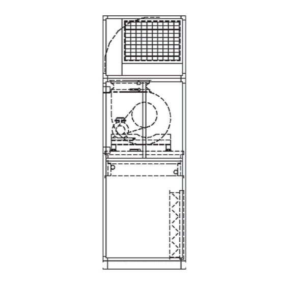
3.7.1 SAFETY EQUIPMENTS The installerwill provide the electrical connection of the safety switches (24 V microswitches) and the ceiling lamps installed inside the sections. The supply of motor current will have to be foreseen only from the electric control board. Access doors to fan section are equipped with adhesive label warning danger for moving elements and electric current. -
Page 17: Belts Tension
• provide the electrical connection 24 [V] of safety microswitches installed on inspection doors of fan sections or doors under pressure. The opened door must exclude the running of the motor. The supply of current will have to be foreseen only from the electric control board; •... -
Page 18: Bearings Lubrification
A practical method to verify the belt tension is the following: • measure the free length (T); • for each belt apply a perpendicular force with the thumb, in the center line of the free length (T). The correct working of the belt corresponds to the following deflection value (f): Length (T) [mm] Deflection (f) [mm] 0‑500... -
Page 19: Electrical Connections
3.8 ELECTRICAL CONNECTIONS 3.8.1 MOTORS The electric motors used have the following features: • complying with CEI‑UNEL regulations and IEC international regulations; • closed construction and external ventilation; • squirrel cage rotor; • three‑phase asynchronous with winding: 2301400 [Volt] 50 [ Hz] Eurotension up to capacity of 5,5 [kVVI included; 4001690[Volt] 50[ Hz] Eurotension for bigger capacities;... -
Page 20: Electric Pumps
• foresee suitable electrical protections; • make the possible cleaning of the resistors by vacuum cleaner. 3.8.3 ELECTRIC PUMPS • read carefully the use and maintenance manual of the electric pump before connecting it • electrically connectthe pump following the instructions enclosed to it •... -
Page 21: Absolute Filters
The check of the clogging level can be made by manometer or differential pressure gauge with alarm. The pressure drop by clogged filter is variable according to the model and the efficiency of the filter installed. Usually the bag filters are supplied not mounted and packed into boxes. At the first starting, let the Unit run for some hours without bag filters but with prefilters. -
Page 22: Activated Carbon Filters
Verify that the electrical absorption of motors is lower than the one of the specification tag. In case the absorption is higher, immediately inform NOVAIR customer setvice and stop the working of the Unit or temporarily make artificial pressure drops in... -
Page 23: Operational Maintenance Layout
6 OPERATIONAL MAINTENANCE LAYOUR Before any operation of maintenance be sure that the unit is not and by chance or accidentally cannot be electrically driven. Therefore at each service switch the electrical feeding off. Frequence of the operations Type of Operation 1 Week 15 Days 1 Month 3 Month 6 Month... -
Page 24: Monthly Checks
6.1 MONTHLY CHECKS A) FAN ROTOR CHECK Check the cleanliness of the fan rotor. Otherwise clean it by compressed air jetwithout damaging it. B) BELT CHECK • check the correct belt tension following the procedure described at par, 3.7.3. If it is necessary to tension it, act on the screw of the motor slide;... - Page 25 • dismount the filters frames, the ventilation units, the recovery units, etc.. All the components installed inside the NOVAIR Units are screwed to the bearing struc‑ ture and they don’t need special tools to be dismounted;...
-
Page 26: Localization Of Failures
8 LOCALIZATION OF FAILURES SYMPTOMS CAUSE • obstructions in the circuit of the plant, in the grids, ducts, etc. • rotation speed too low • pressure higher than required Insufficient air volume • inverted direction of rotation of fan • underestimated pipes leakages •...
Need help?
Do you have a question about the CTA 76 and is the answer not in the manual?
Questions and answers