
Related Manuals for Riken Keiki GX-9000H


Summarization of Contents
1 Product Overview
1-1 Introduction
Introduction to the GX-9000 Series portable gas detector and manual.
1-2 Intended Use
Details the multi-gas detector's capabilities and target gases.
2 Important Safety Information
2-1 Danger Information
Critical safety warnings related to explosion-proofing and product usage.
2-2 Warnings
General warnings regarding product operation, sensor handling, and environmental conditions.
2-3 Precautions
Precautions for use in specific environments, condensation, and maintenance.
2-4 Safety Information Overview
Provides an overview of product safety features, power sources, and specific model certifications.
3 Product Configuration
3-1 Main Unit and Accessories
Details the main unit and lists available accessories for the GX-9000 and GX-9000H.
3-1-3 Optional Accessories
Lists optional accessories available for purchase separately.
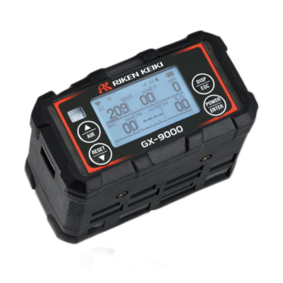
3-2 Part Names and Functions
Identifies and describes the main unit and battery unit components.
3-2-2 Control Panel Functions
Describes the buttons and their functions on the GX-9000 control panel.
3-2-3 LCD Display Elements
Explains the various display elements shown on the LCD for GX-9000 and GX-9000H models.
4 Alarm Functions
4-1 Gas Alarm Types
Defines the different types of gas alarms and their priority levels.
4-2 Gas Alarm Setpoints
Details default alarm setpoints for various combustible, CO2, O2, H2S, and toxic gases.
4-3 Gas Alarm Patterns
Illustrates buzzer sounding and LED flashing patterns for different alarm types.
4-4 Fault Alarm Patterns
Describes fault alarms for system, battery, clock, sensor, and flow rate abnormalities.
4-5 Operating Temperature Range Warning
Explains the warning triggered when the product operates outside the specified temperature range.
5 Usage Instructions
5-1 Usage Notes
Key checks and precautions before starting gas concentration measurement.
5-2 Battery Unit Handling
Procedure for removing and attaching the lithium ion or dry battery unit.
5-2-2 Charging the Lithium-Ion Battery
Instructions for charging the BUL-9000 lithium ion battery unit using the AC adapter.
5-2-3 Replacing Dry Batteries
Procedure for replacing dry batteries in the BUD-9000 unit.
5-3 Connecting the Gas Sampling Rod
Details on how to connect the gas sampling rod to the main unit to prevent dust ingress.
5-4 Turning On the Power
Describes the power-on sequence, display checks, and initial modes.
5-5 H2S Measurement Mode Selection (GX-9000H)
How to switch between H2S high and low concentration measurement modes on the GX-9000H.
5-6 Performing Fresh Air Adjustment
Procedure for performing fresh air adjustment, including use of activated carbon filter.
5-7 Measurement Operation
General precautions and guidelines for performing gas measurements with the product.
5-7-1 Measuring Gas Concentration
Steps for measuring gas concentrations and understanding sensor readings.
5-7-2 Combustible Gas Range Changeover
Explains automatic switching between %LEL and vol% ranges for combustible gases.
5-7-3 Basic Operating Flow in Measurement Mode
Illustrates the basic operational flow within measurement mode for GX-9000.
5-7-4 Confirmation Beep Operation
Details the confirmation beep function for alarms and tests, and its settings.
5-8 Recording Gas Concentration Logs
Procedure for recording gas concentration data using the snap logger function.
5-9 Stopping the Pump
Instructions on how to stop the product's internal pump.
5-10 Turning Off the Power
Procedure for safely turning off the product's power, including purging.
6 Settings (Display Mode)
6-1 Display Mode Items
Lists and describes the various items displayed in the product's display mode.
6-2 Switching to Display Mode
How to navigate between measurement mode and display mode screens.
6-3 Checking Settings
Overview of functions for checking and clearing settings.
6-3-1 Clearing Peak Value
Procedure to clear the maximum measured gas concentration (PEAK value).
6-3-2 Displaying Snap Logger Data
How to view recorded gas concentration and alarm status from the snap logger.
6-3-3 Displaying Adjustment Records
How to view dates of gas adjustments performed for each sensor.
6-3-4 Displaying Bump Test Records
How to view dates of bump tests performed for each sensor.
6-3-5 Displaying Alarm Setpoints
How to view full scale, first alarm, second alarm, STEL, and TWA setpoints.
6-4 Display Mode Settings
Options for configuring various display settings.
6-4-1 Setting NCF/TEF Sensor Range
Configures range selection for NCF and TEF sensors (AUTO, VOL, LEL).
6-4-2 Combustible Gas Conversion Selection
Sets the conversion gas for displaying combustible gas concentrations.
6-4-3 VOC Conversion Gas Selection
Sets the conversion gas for displaying VOC concentrations.
6-4-4 Setting User ID
Assigns a user ID for individual identification.
6-4-5 Setting Station ID
Assigns a station ID to identify measurement points.
6-4-6 Setting Bluetooth Connection
Enables or disables connection to Bluetooth devices for smartphone communication.
6-4-7 Setting Buzzer Volume
Adjusts the buzzer volume level to HIGH or LOW.
6-4-8 Switching Display Language to English
Sets the display language to English for ATEX/IECEx models.
6-4-9 Switching Display Language to Japanese
Sets the display language to Japanese for Japan Ex models.
7 Settings (User Mode)
7-1 User Mode Display Items
Lists the main functions accessible within the user mode menu.
7-2 Switching to User Mode
Procedure for accessing the user mode menu from measurement mode.
7-3 Gas Alarm Settings
Configuration options for gas alarms, including setpoints.
7-3-1 Setting Alarm Setpoints
Allows setting individual alarm setpoints for each sensor based on resolution.
7-3-2 Setting Alarm Type
Configures the alarm type (H-HH, L-LL, L-H) for each sensor.
7-3-3 Setting Alarm Pattern
Sets the alarm pattern to LATCHING or SELF RESET.
7-3-4 Resetting Alarm Setpoints
Restores all alarm setpoints to their default factory settings.
7-3-5 Enabling/Disabling Alarm Function
Enables or disables the gas alarm function; alarms do not operate when OFF.
7-4 Other User Mode Settings
Miscellaneous settings configurable within user mode.
7-4-1 Setting the Buzzer
Configures buzzer behavior for operations, alarms, and warnings.
7-4-2 CO2 Fresh Air Adjustment Setting
Enables or disables fresh air adjustment for the CO2 sensor.
7-4-3 Selecting Gas Type for Base Gas Adjustment
Selects gas type (N2 or INERT) for base gas adjustment of TEF sensors.
7-4-4 Setting Date and Time
Sets the internal clock date and time for the product.
7-4-5 Setting Display Language
Selects the screen display language from a list of available languages.
7-4-6 Displaying Version Information
Shows version information for product modules and options.
8 Maintenance
8-1 Maintenance Intervals and Items
Lists items requiring daily, monthly, and regular maintenance checks.
8-2 Performing Gas Adjustment
General guide for performing gas adjustments, requiring specific tools and calibration gas.
8-2-1 Preparation for Gas Adjustment
Lists required equipment and methods for supplying calibration gas.
8-2-2 Performing Fresh Air Adjustment
Procedure for performing fresh air adjustment, crucial before measuring gas concentrations.
8-2-3 Performing CO2 Zero Adjustment
Steps for performing CO2 zero adjustment, necessary for carbon dioxide sensors.
8-2-4 Performing Base Gas Adjustment
Procedure for base gas adjustment, required for TEF sensors after fresh air adjustment.
8-2-5 Setting Span Adjustment Cylinders
Sets sensor groups and default cylinder assignments for span adjustment.
8-2-6 Performing Span Adjustment
Procedure for performing span adjustment using prepared calibration gases.
8-3 Performing Bump Tests
Steps for conducting bump tests to verify sensor functionality and calibration.
8-4 Performing Alarm Tests
Procedure to test the product's alarms by activating setpoints.
8-5 Cleaning Procedure
Instructions for cleaning the product exterior, emphasizing safe cleaning agents.
8-6 Parts Replacement
Lists consumable parts and recommended replacement intervals.
8-6-1 Periodic Replacement Parts
Details consumable parts requiring periodic replacement and their intervals.
8-6-2 Gas Sampling Rod Dust Filter Replacement
Procedure for replacing the dust filter in the gas sampling rod probe.
8-6-3 VOC Sensor Maintenance
Instructions for cleaning the LED and replacing the pellet in VOC sensors.
9 Storage and Disposal
9-1 Storage Procedures
Guidelines for storing the product in appropriate environmental conditions.
9-2 Procedures for Use After Storage
Steps to take before resuming use after the product has been stored.
9-3 Product Disposal
Instructions for proper product and battery disposal according to regulations.
10 Troubleshooting
10-1 Product Abnormalities
Common symptoms and causes of product abnormalities with suggested actions.
10-2 Reading Abnormalities
Troubleshooting guide for abnormal readings, slow response, and adjustment issues.
11 Product Specifications
11-1 Product Specifications Overview
General specifications for the GX-9000 portable gas detector.
11-1-1 GX-9000 Specifications
Detailed technical specifications for the GX-9000 model.
11-1-2 GX-9000H Specifications
Detailed technical specifications for the GX-9000H model.
11-2 Sensor Specifications
Overview of sensor specifications.
11-2-1 Combustible Gas Sensors
Technical specifications for new ceramic type and thermal conductivity type sensors.
11-2-2 Carbon Dioxide Sensor
Technical specifications for the NDIR carbon dioxide sensor.
11-2-3 Oxygen Sensor
Technical specifications for the electrochemical type oxygen sensor.
11-2-4 Toxic Gas Sensors
Technical specifications for electrochemical type toxic gas sensors.
11-2-5 VOC Sensors
Technical specifications for photo-ionization type (PID) VOC sensors.
12 Appendix
12-1 Data Logger Function
Details the functions of the data logger for recording measurement results and events.
12-2 100 %LEL Conversion List
Table of standard conversions between 100 %LEL and ppm for various gases.
12-3 Zero Suppression Function
Explains the zero suppression function for stabilizing readings and preventing fluctuations.
12-4 Zero Follower Function
Describes the zero follower function for stabilizing zero points affected by sensor drift.
12-5 VOC Conversion Gas List
List of VOCs with conversion factors for 10.6 eV and 10.0 eV sensors.
Need help?
Do you have a question about the GX-9000H and is the answer not in the manual?
Questions and answers